Ametek Reichert ClearChart2 User manual

Digital Acuity System
User’s Guide

ClearChart 2 Digital Acuity System User’s Guide 13760-101 Rev. H
2
2
©2013 AMETEK, Inc.
Reichert, Reichert Technologies, Auto Phoroptor RS, Phoroptor and ClearChart are registered trademarks of
Reichert, Inc.
AMETEK is a registered trademark of AMETEK, Inc.
All other trademarks are property of their respective owners.
The information contained in this document was accurate at time of publication. Specifications subject to change
without notice. Reichert, Inc. reserves the right to make changes in the product described in this manual without
notice and without incorporating those changes in any products already sold.
ISO 9001/13485 Certified – Reichert products are designed and manufactured under quality processes meeting
ISO 9001/13485 requirements.
No part of this publication may be reproduced, stored in a retrieval system, or transmitted in any form or by any
means, electronic, mechanical, recording, or otherwise, without the prior written permission of Reichert, Inc.
Caution: Federal law restricts this device to sale by or on the order of a licensed
physician. Rx only.

ClearChart 2 Digital Acuity System User’s Guide 13760-101 Rev. H 3
Warnings and Cautions.......................................................................................... 4
Symbol Information .................................................................................................6
Introduction .............................................................................................................7
Indications for Use......................................................................................7
Contraindications........................................................................................7
Unpacking and Contents.........................................................................................7
Installation, Features, & Functions .........................................................................8
Wall Mounting Instructions .........................................................................8
Application of Input Power..........................................................................9
Disconnection of Input Power.....................................................................9
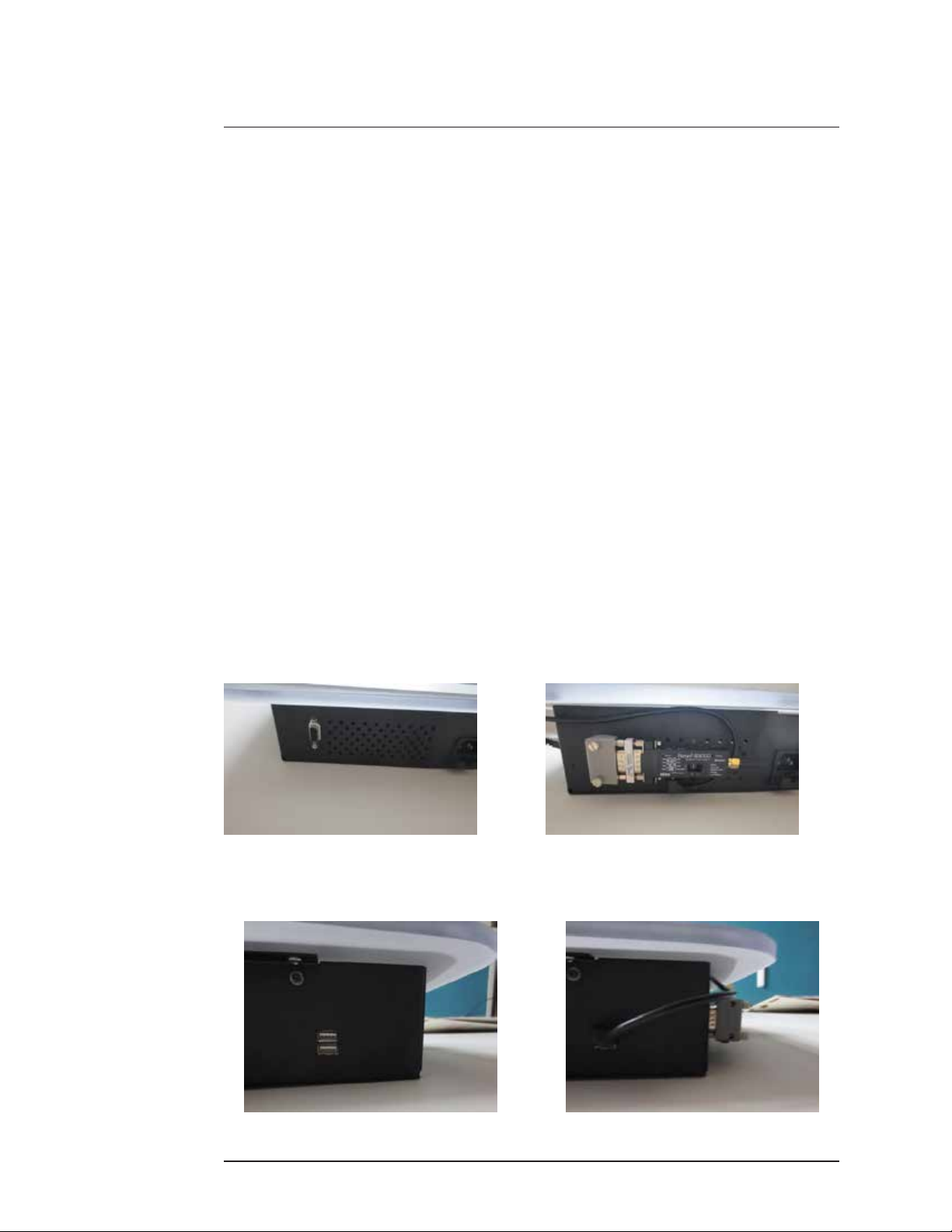
Communication Ports .................................................................................9
Connection with the Auto Phoroptor RS®Auto Refraction System ..........10
Wired Connection................................................................................10
Wireless Connection ...........................................................................10
Remote Control Power .............................................................................12
Remote Control Layout ............................................................................12
ConguringtheClearChart2....................................................................14
Optotypes .................................................................................................17
Size Progressions ....................................................................................18
Remote Control Functions........................................................................19
Video and Image File Feature..................................................................26
Video and Image File Parameters............................................................26
Videos.......................................................................................................26
Importing and Accessing Video Files ..................................................26
Organizing Video Files ........................................................................27
Deleting Video Files.............................................................................27
Images......................................................................................................27
Importing and Accessing Image Files .................................................27
Organizing Image Files .......................................................................28
Deleting Image Files............................................................................28
Changing the Screen Saver ................................................................28
Restoring the Default Screen Saver....................................................29
ClearChart 2 and Auto Phoroptor RS®Communication ...........................30
Setup ...................................................................................................30
Optotype Selection ..............................................................................31
Special Test Charts..............................................................................32
Other Functions...................................................................................32
Cleaning and Maintenance ...................................................................................33
Cleaning ClearChart 2..............................................................................33
Fuse Replacement ...................................................................................33
Troubleshooting ....................................................................................................34
Specications........................................................................................................35
Disposal....................................................................................................35
Software Revision ....................................................................................35
Classications...........................................................................................36
Guidance and Manufacturer’s Declarations .........................................................37
Warranty................................................................................................................41
Notes ................................................................................................................... 43
Contents

Reichert, Inc. (Reichert) is not responsible for the safety and reliability of this
instrument when:
• Assembly,disassembly,repair,ormodicationismadebyunauthorized
dealers or persons.
• Instrument is not used in accordance with this User’s Guide.
WARNING: AN INSTRUCTION THAT DRAWS ATTENTION TO RISK OF INJURY OR DEATH.
WARNING: UNITED STATES FEDERAL LAW AND EUROPEAN REGULATIONS REQUIRE
THAT THIS DEVICE BE PURCHASED ONLY BY A PHYSICIAN OR A PERSON ACTING
ON BEHALF OF A PHYSICIAN.
WARNING: THIS INSTRUMENT SHOULD BE USED IN STRICT ACCORDANCE
WITH THE INSTRUCTIONS OUTLINED IN THIS USER’S GUIDE. THE SAFETY
OF THE OPERATOR AND THE PERFORMANCE OF THE INSTRUMENT CANNOT
BE GUARANTEED IF USED IN A MANNER NOT SPECIFIED BY REICHERT
TECHNOLOGIES.
WARNING: DO NOT REPAIR OR SERVICE THIS INSTRUMENT WITHOUT
AUTHORIZATION FROM THE MANUFACTURER. ANY REPAIR OR SERVICE TO THIS
INSTRUMENT MUST BE PERFORMED BY EXPERIENCED PERSONNEL OR DEALERS
WHO ARE TRAINED BY REICHERT OR SERIOUS INJURY TO THE OPERATOR OR
PATIENT MAY OCCUR.
WARNING: MODIFICATIONS TO THIS INSTRUMENT ARE NOT ALLOWED. ANY
MODIFICATION TO THIS UNIT MUST BE AUTHORIZED BY REICHERT OR SERIOUS
INJURY TO THE OPERATOR OR PATIENT MAY OCCUR.
WARNING: IF THIS INSTRUMENT IS MODIFIED, APPROPRIATE INSPECTION AND
TESTING MUST BE CONDUCTED TO ENSURE CONTINUED SAFE USE OF THIS
INSTRUMENT.
WARNING: TO AVOID RISK OF ELECTRIC SHOCK, THIS EQUIPMENT MUST ONLY BE
CONNECTED TO A SUPPLY MAINS WITH PROTECTIVE EARTH OR DAMAGE TO THIS
INSTRUMENT AND/OR INJURY TO THE OPERATOR OR PATIENT MAY OCCUR.
WARNING: ENSURE THAT THE VOLTAGE APPLIED TO THE UNIT IS THE SAME AS
THE VOLTAGE THAT IS INDICATED ON THE DATA PLATE OR DAMAGE TO THE UNIT
MAY OCCUR.
WARNING: THIS INSTRUMENT MUST BE PLUGGED INTO AN OUTLET WITH AN EARTH
GROUND. DO NOT REMOVE OR DEFEAT THE EARTH GROUND CONNECTION ON
POWER INPUT CONNECTOR OR THE UNIT’S POWER CORD OF THIS INSTRUMENT
OR DAMAGE TO IT AND/OR INJURY TO THE OPERATOR OR PATIENT MAY OCCUR.
WARNING: THIS INSTRUMENT IS NOT SUITABLE FOR USE IN THE PRESENCE OF
FLAMMABLE ANESTHETIC MIXTURES, SUCH AS OXYGEN OR NITROUS OXIDE.
WARNING: THE EQUIPMENT OR SYSTEM SHOULD NOT BE USED ADJACENT TO
OR STACKED WITH OTHER EQUIPMENT AND THAT IF ADJACENT OR STACKED USE
IS NECESSARY, THE EQUIPMENT OR SYSTEM SHOULD BE OBSERVED TO VERIFY
NORMAL OPERATION IN THE CONFIGURATION IN WHICH IT WILL BE USED.
WARNING: THE BATTERY SHOULD ONLY BE REPLACED WITH THE BATTERY
SPECIFIED IN THIS MANUAL. USE OF ANOTHER BATTERY MAY CAUSE FIRE OR AN
EXPLOSION.
WARNING: DO NOT PLACE A SHORTING DEVICE BETWEEN THE BATTERY
TERMINALS, OR ALLOW THE BATTERY TO BECOME WET. MISUSE OR IMPROPER
DISPOSAL OF THIS BATTERY MAY CAUSE IT TO BECOME VERY HOT, IGNITE OR
EXPLODE. DAMAGE TO THIS UNIT AND/OR SERIOUS PERSONAL INJURY MAY
RESULT.
ClearChart 2 Digital Acuity System User’s Guide 13760-101 Rev. H
4
Warnings & Cautions

WARNING: DO NOT RECHARGE THE BATTERIES. THE BATTERY IS NOT DESIGNED
TO BE CHARGED BY ANY ELECTRICAL SOURCE. CHARGING COULD GENERATE
GAS AND INTERNAL SHORT-CIRCUITING, LEADING TO DISTORTION, LEAKAGE,
OVERHEATING, EXPLOSION OR FIRE.
WARNING: DO NOT EXPOSE THE BATTERIES TO TEMPERATURES ABOVE 140ºF,
DISASSEMBLE THE BATTERIES, OR DAMAGE TO THIS UNIT AND/OR SERIOUS
PERSONAL INJURY MAY RESULT.
WARNING: NEVER ALLOW LIQUID LEAKING FROM THE BATTERY TO GET IN YOUR
EYES OR MOUTH AS THIS LIQUID COULD CAUSE SERIOUS PERSONAL INJURY. IF IT
COMES IN CONTACT WITH YOUR EYES OR MOUTH, FLUSH THEM IMMEDIATELY WITH
PLENTY OF WATER AND CONSULT A PHYSICIAN.
WARNING: ALWAYS KEEP BATTERIES OUT OF THE REACH OF INFANTS AND
YOUNG CHILDREN TO PREVENT THEM FROM BEING SWALLOWED. IF SWALLOWED,
CONSULT A PHYSICIAN IMMEDIATELY.
WARNING: THE USE OF ACCESSORIES OR CABLES OTHER THAN THOSE SPECIFIED,
WITH THE EXCEPTION OF THOSE SOLD BY THE MANUFACTURER AS REPLACEMENT
PARTS FOR THE INTERNAL COMPONENTS, MAY RESULT IN INCREASED EMISSIONS
OR DECREASED IMMUNITY OF THE EQUIPMENT OR SYSTEM.
CAUTION: AN INSTRUCTION THAT DRAWS ATTENTION TO THE RISK OF DAMAGE TO
THE PRODUCT.
CAUTION: DO NOT USE SOLVENTS OR STRONG CLEANING SOLUTIONS ON ANY PART
OF THIS INSTRUMENT AS DAMAGE TO THE UNIT MAY OCCUR. SEE MAINTENANCE
SECTION FOR DETAILED CLEANING INSTRUCTION.
CAUTION: USE OF AMMONIA BASED CLEANERS ON THE LIQUID CRYSTAL DISPLAY
(LCD) MAY CAUSE DAMAGE TO THE DISPLAY. SEE MAINTENANCE SECTION FOR
DETAILED CLEANING INSTRUCTION.
CAUTION: PORTABLE AND MOBILE RF COMMUNICATIONS EQUIPMENT CAN EFFECT
MEDICAL ELECTRICAL EQUIPMENT.
CAUTION: THE INTERNAL CIRCUITRY OF THE INSTRUMENT CONTAINS
ELECTROSTATIC DISCHARGE SENSITIVE DEVICES (ESDS) THAT MAY BE SENSITIVE
TO STATIC CHARGES PRODUCED BY THE HUMAN BODY. DO NOT REMOVE THE
COVERS WITHOUT TAKING PROPER PRECAUTIONS.
CAUTION: MEDICAL ELECTRONIC EQUIPMENT NEEDS SPECIAL PRECAUTIONS
REGARDING EMC AND NEEDS TO BE INSTALLED AND PUT INTO SERVICE ACCORDING
TO THE EMC INFORMATION PROVIDED IN THE ACCOMPANYING DOCUMENTS.
CAUTION: THIS INSTRUMENT IS NOT TO BE USED NEAR HIGH-FREQUENCY EMITTING
SURGICAL EQUIPMENT.
CAUTION: THIS INSTRUMENT IS NOT INTENDED TO BE CONNECTED TO EQUIPMENT
OUTSIDE THE CONTROL OF REICHERT INC. OR MUST BE TESTED TO AN APPLICABLE
IEC OR ISO STANDARDS.
CAUTION: DO NOT INSTALL ANY ADDITIONAL SOFTWARE OTHER THAN WHAT WAS
SUPPLIED WITH THIS INSTRUMENT. INSTALLATION OF ADDITIONAL SOFTWARE
MAY CAUSE UNEXPECTED OPERATION RESULTING IN MALFUNCTION OF THIS
INSTRUMENT.
ClearChart 2 Digital Acuity System User’s Guide 13760-101 Rev. H 5
Warnings & Cautions (continued)

Symbol Information
The following symbols appear on the instrument:
Caution symbol indicating important operating and maintenance
instructions that are included in this User’s Guide
Alternating Current Power
Protective Earth Connection
ON / OFF
REF Catalog Number
SN Serial Number
2013
Date of Manufacture
Waste of Electrical and Electronic Equipment
Compliance to Medical Device Directive 93/42/EEC
Authorized to mark given by Intertek ETL Semko for
conformance with electrical standards
Fragile Contents in Shipping Container - handle with care
Keep Dry - Package shall be kept away from rain
This Way Up - Indicates correct upright position of package
Authorized Representative in European Community
Consult Instructions for Use
ClearChart 2 Digital Acuity System User’s Guide 13760-101 Rev. H
6

Unpacking and Contents
ClearChart 2 Digital Acuity System User’s Guide 13760-101 Rev. H 7
Introduction
Congratulations on your purchase of the ClearChart® 2.
The ClearChart 2 is a remote controlled digital acuity system that has been designed to
provide a comprehensive, versatile, and convenient system for measuring visual acuity.
This User’s Guide is designed as a training and reference manual for operation,
maintenance, and troubleshooting. We recommend that you read it carefully prior to
use and follow the instructions in the guide to ensure optimum performance of your
new instrument. Properly trained eyecare professionals such as ophthalmologists,
optometrists, opticians and eye care technicians should operate this instrument.
Please retain this manual for future reference and to share with other users. For
additional copies of this manual or questions related to the ClearChart 2, contact your
local authorized Reichert dealer or contact our Customer Service department directly at:
Tel: 716-686-4500
Fax: 716-686-4555
E-mail: [email protected]
Indications for Use
The indications for use include visual acuity for determining patient objective refraction.
Contraindications
None.
Great care has been taken to deliver your ClearChart 2 to you. The packaging was
specicallydesignedtotransportthisinstrument.Pleaseretainthepackagingforfuture
use in case transportation is required. To remove the ClearChart 2 from it packaging:
1. Remove the accessories from the top pieces of foam in the box.
2. Remove the two top pieces of foam from the box.
3. Lift the ClearChart 2 out of the box.
The items listed below should be included in the ClearChart 2 packaging container:
• ClearChart 2 (P/N 13760)
• Remote Control (P/N 13762)
• Two AAA batteries (P/N 13950000-902)
• Power Cord * (P/N WCBL10018)
• Wall Mount Bracket (P/N 13750-008)
• Two Screws (P/N X76317)
• Two Drywall Fasteners (P/N X76318)
• User’s Guide (P/N 13760-101)
If any of these items are missing, please contact the Reichert Customer Service
Department. Contact information can be found on the back cover of this manual.
* This PN is for 110V operation. An alternate medical grade power cord for your region may need
to be obtained as required by your local laws and ordinances for use with a medical grade device.

Wall Mounting Instructions
WARNING: IT IS IMPORTANT TO SAFELY SECURE THE EQUIPMENT. UNSECURED
EQUIPMENT COULD POSSIBLY BECOME DISLODGED AND FALL, CAUSING INJURY TO
EITHER THE PATIENT OR EXAMINER.
WARNING: CARE MUST BE TAKEN TO ARRANGE THE CABLES FOR THE
ACCESSORIES SUCH THAT THEY DO NOT PRESENT A TRIPPING HAZARD TO THE
EXAMINER OR A DANGER TO THE PATIENT.
WARNING: POSITION THE CLEARCHART 2 ON THE WALL SO THAT IT IS NOT
DIFFICULT TO OPERATE THE DISCONNECTION DEVICE (PLUG).
Note: Make sure the position you choose to mount your ClearChart 2 is within the
reach of a power outlet.
Direct-Throw: Your ClearChart 2 must be positioned at patient eye level directly in
front of the patient. The minimum test distance is 6 feet (1.83 meters) with a maximum
test distance of 31 feet (9.5 meters). Refer to the Direct Throw illustration in this
section.
Mirror Arrangement:Arstsurfacemirrorisausefulspace-savingdevicetoincrease
the patient testing distance when the room does not permit a direct-throw arrangement.
Typically, your ClearChart 2 will be positioned higher than patient eye level so that
the examiner will not interfere with the patient’s view of the ClearChart 2. Arrange the
ClearChart 2 and mirror so that the ClearChart 2 can be seen by the patient through
the mirror.
1. Find an appropriate spot on the wall that will support the ClearChart, which will hang
from the Mounting Bracket attached to the wall inserts included with the accessories.
Ensure that the refraction distance meets the requirements for either Direct-throw or
Mirror Arrangement.
2. Level the supplied Wall Mount Bracket with the metal tabs facing up and out on your
wall and mark the holes on the wall.
3. Using the supplied Drywall Fasteners, place the tip of each
fastener on the marked hole and using a hammer tap the
insert into the wall as far as the threads on the insert. Using
a phillips-head screwdriver, screw the fastener into the wall
untilthesurfaceisushwiththewall.RefertotheDrywall
Fastener picture for a sample of correct installation.
CAUTION: DO NOT OVER DRIVE THE
INSERTS INTO THE WALL.
4. Place the Wall Mount Bracket on the wall,
and screw the supplied screws into the
Drywall Fasteners.
5. Hang the ClearChart 2 by lining-up the
holes on the back of unit with the metal
tabs of the Wall Mount Bracket and hang
the unit on these tabs.
Installation, Features, & Functions
Drywall Fastener
Mounting the Wall Bracket
ClearChart 2 Digital Acuity System User’s Guide 13760-101 Rev. H
8

ClearChart 2 Digital Acuity System User’s Guide 13760-101 Rev. H 9
Installation, Features, & Functions (continued)
Application of Input Power
1. Using the provided power cord, insert the female end into the power input recep-
tacle located at the bottom of the instrument.
2. Plug the male end of the power cord into a wall outlet of the appropriate voltage.
Input voltage must not exceed the range specified on the ClearChart 2 data plate.
3. Set the ON / OFF switch to ON ( I ).
Disconnection of Input Power
At any time, the power switch can be set to OFF. The unit does not have a power
down sequence. To terminate operation of the ClearChart 2, press the ON / OFF
switch to the OFF position (O).
Note: If the ClearChart 2 is intended to be OFF for an extended period of time, the
ClearChart 2 can be disconnected from power by detaching the power cord
from the receptacle.
Note: To extend the life of the screen, it is recommended to shut the instrument off at
the end of the day and on the weekends.
Communication Ports
The ClearChart 2 has a 9 pin female serial port on the bottom of the instrument hous-
ing that can be used for either hard-wired or wireless connection to the Reichert Auto
Phoroptor RS®Auto Refraction system.
ClearChart 2 also has two exposed USB ports on the left side of the housing (when
facing the instrument) to power a wireless serial adapter.

ClearChart 2 Digital Acuity System User’s Guide 13760-101 Rev. H
10
Connection with the Auto Phoroptor RS Auto Refraction System
The ClearChart 2 can be configured for bi-directional communication with the Auto
Phoroptor RS automated refraction system. This can be achieved with a hardwired
serial connection or with wireless communication accessories.
Wired Connection
Wired communication between the ClearChart 2 and the Auto Phoroptor RS requires
connection of a NULL modem serial cable with 9 pin male connector on one end and 9
pin female connector at the other end. The cable should be connected to the serial port
on the ClearChart 2 and the serial port labeled “Projector” on the Auto Phoroptor RS
Central Unit.
Note: The Reichert part number for the interface cable between the Auto Phoroptor
RS and the ClearChart 2 is: 16200-440.
Serial port in the bottom of
the ClearChart 2 housing
Serial port for connection
of ClearChart 2 on the Auto
Phoroptor RS Central Unit
Wireless Connection
A wireless connection between the ClearChart 2 and the Auto Phoroptor RS can be
established with a pair of Bluetooth®serial adapters. One serial adapter should be
connected to the serial port on the bottom of the ClearChart 2 housing and can be
powered through the USB connection on the side of the device or with a separate AC
adapter.
Wireless serial adapter
Order Reichert Bluetooth Kit 1
(Part number # 16766)
forthisconguration
USB Connection
Installation, Features, & Functions (continued)

ClearChart 2 Digital Acuity System User’s Guide 13760-101 Rev. H 11
Connection with the Auto Phoroptor RS Auto Refraction System (continued)
The second serial adapter should be connected to the Projector serial port on the
Auto Phoroptor RS Central Unit and powered with an adapter plugged into an outlet.
Note: Follow the instructions provided by the manufacturer of the wireless serial
adapterstosetthedevicesfortheserialportconguration.Instructionsare
provided with Reichert Bluetooth Kits.
Power Cable
Wireless Serial Adapter
(Order Reichert Bluetooth
Kit #5 Part Number 13769)
Installation, Features, & Functions (continued)

ClearChart 2 Digital Acuity System User’s Guide 13760-101 Rev. H
12
Installation, Features, & Functions (continued)
Remote Control Power
1. Remove the back of the remote control by sliding it in the direction of the arrow.
2. Put in two AAA batteries in the position shown on the remote control.
Remote Control Layout
The remote control will operate all the screens on your ClearChart 2.
1. Lines of Same Sized
Optotypes
2. Lines of Descending
Sized Optotypes
3. Single Vertical Line/Descending/
Normal Optotypes
4. Single Letter
5. RED/GREEN Test
6. Randomize Optotype
7. View Size of Optotype
Currently Displayed
8. Left Arrow
9. Up Arrow (Volume Up)
10. Right Arrow
11. Down Arrow (Volume Down)
12. Menu Button
13. Educational Slides
14. Save Button
15. Contrast Up (MAX)
16. Contrast Down (MIN)
17. Light (3 Illumination Levels)
18. Contrast Mode
19. 400 Optotype Size
20. 200 Optotype Size
21. 100 Optotype Size
22. 80 Optotype Size
23. 60 Optotype Size
24. 50 Optotype Size
25. 40 Optotype Size
26. 30 Optotype Size
27. 25 Optotype Size
28. 20 Optotype Size
29. 15 Optotype Size
30. 10 Optotype Size
31. Default/Change Optotype
32. Alternate Optotype
33. Animate
34. Movie
35. Cross Cylinder Test
36. Astigmatic Dial
37. Astigmatic T
38. Fixation Targets
39. Color Suppression
40. Horizontal Disparity
41. Vertical Disparity
42. Worth Four Dot Test
43. Crowding Bars
44. Not Active - For Future Use
45. Dark (Screen Saver)

ClearChart 2 Digital Acuity System User’s Guide 13760-101 Rev. H 13
13
4321
4433
3943
4245
41403816
373635
15
3271718
31
14 11
12
9
10
8
6
5
30
29
28
27
26
25
24
23
22
21
20
19
34
Installation, Features, & Functions (continued)

ClearChart 2 Digital Acuity System User’s Guide 13760-101 Rev. H
14
Conguring the ClearChart 2
Press the ON/OFF switch located on the side of the instrument. The ClearChart 2 will
boot-up. When the ClearChart 2 welcome screen appears, press the MENU button
ontheremotetoenterthecongurationmode.UsetheUPandDOWNarrowsto
navigate through different options.
ROOM
Using the LEFT/RIGHT arrows on your remote, select DIRECT THROW or
MIRROREDbasedonthecongurationofyourofce.Whenyouarenished,press
the DOWN arrow.
Using the LEFT/RIGHT arrows on your remote, select METRIC or ENGLISH units
based on which units you use to measure your refraction distance. When you are
nished,presstheDOWNarrow.
Direct Throw
ClearChart
Patient
Patient to Screen Distance
Mirror Set Up
ClearChart
Patient
Patient to Mirror Distance
Mirror
ClearChart to Mirror Distance
Installation, Features, & Functions (continued)

ClearChart 2 Digital Acuity System User’s Guide 13760-101 Rev. H 15
ACUITY NOTATION
Using the LEFT/RIGHT arrows on your remote, select SNELLEN, METRIC, or
DECIMALforyouracuitynotation.Whenyouarenished,presstheDOWNarrow.
• Snellen - displayed as distance in feet / size in mm
• Metric - displayed as distance in meters / size in mm
• Decimal - displayed as the decimal equivalent for the distance in feet / size in mm
The 20/10 optotypes may not be available at test distances under 12 feet (3.66 meters)
and the 20/400 optotypes may not be available at test distance over 22 feet (6.71
meters).
DISTANCE
Use the MAX and MIN buttons to adjust the testing distance from the patient’s eye
to the screen. The units are either inches or centimeters depending on whether you
choseENGLISHorMETRICearlierinthesetupprocedure.Whenyouarenished,
press the DOWN arrow.
Note: If MIRRORED was selected in the ROOM setup category entered above, then
two distances will be required. First enter the distance from the patient to the
mirror, then enter the distance from the mirror to the screen. Press the DOWN
arrow after each distance is entered.
OPTOTYPES
Using the LEFT/RIGHT arrows on your remote, select the default optotype you would
liketheClearChart2todisplaywhenrststarted.
Available optotypes are:
• 17 Letter • Landolt C • Symbols
• 8 Letter • O Landolt C • Allen Symbols
• Sloan • HOTV
• Tumbling E • Numbers
Note: You will be able to access any optotype while using the ClearChart 2. When you
arenished,presstheDOWNarrow.
ALTERNATE OPTOTYPES
Using the LEFT/RIGHT arrows on your remote, select the alternate optotype you would
like the ClearChart 2 to display when you press ALT OPT on your remote. When you
arenished,presstheDOWNarrow.
LINE PRESENTATION
Using the LEFT/RIGHT arrows on your remote, select the default line presentation you
would like the ClearChart 2 to display.
Presentation types:
• Triple Decreasing • Column • Double Decreasing
• Quadruple/Same • Column Uneven • Triple Same
• Quadruple/Decreasing • Single Line
• Single Letter • Double Same
Note: You will be able to access any line presentation while using the ClearChart 2.
Whenyouarenished,presstheDOWNarrow.
Installation, Features, & Functions (continued)

ClearChart 2 Digital Acuity System User’s Guide 13760-101 Rev. H
16
PROGRESSION
Using the LEFT/RIGHT arrows on your remote, select standard or logmar for the
default size progression you would like the ClearChart 2 to display.
Note: You will be able to change size progression while using the ClearChart 2. When
youarenished,presstheDOWNarrow.
DISPLAY OPTOTYPE SIZE
Using the LEFT/RIGHT arrows on your remote, select whether or not you would like
the optotype size displayed on the screen at all times.
Options are: Display or No Display.
Whenyouarenished,presstheDOWNarrow.
MAXIMUM PER LINE
Using the LEFT/RIGHT arrows on your remote, select the maximum number of
characters you would like displayed on any line.
Options are: 1, 2, ,3, 4, 5, or 6
Whenyouarenished,pressDOWNarrow.
RED/GREEN ADJUST
Using the LEFT/RIGHT arrows on the remote, select recalibrate or factory default. If
you choose to recalibrate your red/green settings, press the DOWN button to enter
adjustment mode. To adjust red (R) use the MIN and MAX buttons to acquire proper
tone. Press the RIGHT arrow key four (4) times to get to green adjust. Use MIN
and MAX to adjust green to desired tone. Next press the DOWN arrow to enable
adjustment of the red tone for the suppression letters. MIN and MAX buttons will
again change the color tone. Press the RIGHT arrow button four (4) times to adjust
the green tone for the suppression letters. Use MIN and MAX buttons to adjust the
color. Press the DOWN arrow to re-enter the initial red/green setup screen. Using the
RIGHT/LEFT arrows, move back to the no change option, then press the DOWN arrow
to leave the red/green menu selection.
SCREEN SAVER
Use the MIN and MAX buttons to set the length of time of non-activity you would like
toelapsebeforethescreensaverstarts.Whenyouarenished,presstheDOWN
arrow. ClearChart 2 will initialize and then display your default optotype with your
defaultlinecongurationandisreadyforuse.
Installation, Features, & Functions (continued)

ClearChart 2 Digital Acuity System User’s Guide 13760-101 Rev. H 17
Optotypes
All of the optotypes contained within the ClearChart 2 conform to the American
National Standard Institute guidelines for general purpose clinical visual acuity charts.
The optotypes are constructed on a 5 x 5 matrix such that their stroke width is
one-fthoftheiroverallsize.LetteroptotypesareofLetterGothictypeface.
The spacing between optotypes of the same size is equal to the width of that size
optotype. The spacing between rows of descending size is equal to the width of the
larger optotype.
The letters found in the seventeen letter set have been traditionally used in many visual
acuity testing situations. This letter set consists of these letters: A B C D E F G H K L
N O P T U V Z.
The eight letter set consists of these letters: C D E K N P U Z. The individual letters of
this set have been shown to be equivalent to the Landolt ‘C’. Because of this, each
letter is essentially equally legible to patients. Unlike the seventeen letter set, no letter
is easier or harder to identify than another. Since these letters can be presented in
many combinations by the ClearChart 2, the few letters in the letter set do not pose
a problem of memorization.
The Sloan Letter Set consists of these letters: C D H K N O R S V Z.
The tumbling ‘E’s and the Landolt ‘C’s are both presented in four positions: up, down,
left, and right.
The Children’s Shape Symbols are four shapes. As
these symbols begin to blur, they are each perceived
as circles.
A second set of shapes for Children consists of the
followingveshapes.Thesesymbolsmaybemore
easily recognized and verbalized by some children than
the Children’s Shape Symbols.
The Allen Symbols are only available up to size 100.
Installation, Features, & Functions (continued)

ClearChart 2 Digital Acuity System User’s Guide 13760-101 Rev. H
18
Size Progressions
When multiple lines of descending size are in use, the line size display is that of the
smallest line. The standard progression has the following visual acuity sizes expressed
as Snellen fractions:
Snellen Snellen(metric) Snellen (decimal)
20/10 6/3.0 2.00
20/15 6/4.5 1.33
20/20 6/6.0 1.00
20/25 6/7.5 0.800
20/30 6/9.0 0.667
20/40 6/12.0 0.500
20/50 6/15.0 0.400
20/60 6/18.0 0.333
20/70 6/21.0 0.286
20/80 6/24.0 0.250
20/100 6/30.0 0.200
20/200 6/60.0 0.100
20/400 6/120 0.050
Another line size progression available in ClearChart 2 is the LogMAR progression.
Thisprogressionhasprovedusefulinprescribinglowvisionmagnicationaidsand
permits a more precise method of scoring visual acuity.
Snellen Snellen(metric) LogMAR
20/10 6/3.0 -0.3
20/12.5 6/3.8 -0.2
20/16 6/4.8 -0.1
20/20 6/6.0 0.0
20/25 6/7.5 0.1
20/32 6/9.5 0.2
20/40 6/12 0.3
20/50 6/15 0.4
20/63 6/19 0.5
20/80 6/24 0.6
20/100 6/30 0.7
20/125 6/38 0.8
20/160 6/48 0.9
20/200 6/60 1.0
20/250 6/76 1.1
20/320 6/96 1.2
20/400 6/120 1.3
When the LogMAR progression is being used, the line size display shows the Snellen
value in the lower right-hand corner with the LogMAR line size next to it.
Installation, Features, & Functions (continued)

RED/GREEN
RANDOM
ClearChart 2 Digital Acuity System User’s Guide 13760-101 Rev. H 19
Remote Control Functions
1. This button will present lines of the same size
of optotypes. Multiple presses of this button will
change the number of lines presented on the
screen from 1 to 4.
Note: At larger optotype sizes, there will be a limit
of how many lines can be displayed.
2. This button will present lines of optotypes
descending in size. Multiple presses of this but-
ton will change the number of lines presented on
the screen from 1 to 4.
Note: At larger optotype sizes, there will be a limit
of how many lines can be displayed.
3. This button will present a single line of optotypes.
The second time you press this button, a single
line of optotypes of descending size will be
displayed. A third press of this button will return
you to normal lines of optotypes.
Note: At larger optotype sizes, there will be a limit
of how many lines can be displayed.
4. This button will present a single optotype. A sec-
ond press of this button will return you to normal
lines of optotypes.
5. This button will initialize RED/GREEN mode. In
this mode, you will be able to change optotypes,
sizes, lines, and line presentation by pressing
other buttons on the remote. To exit the RED/
GREEN mode, simply press this button again.
Note: At larger optotype sizes, there will be a
limit of how many lines can be displayed.
6. Press the RANDOM button to randomize the
current optotypes at its current size. Pressing the
RANDOM button repeatedly will continue to
present random characters of the current
optotype at its current size.
Note: Use the RIGHT arrow button to randomize
single optotypes.
7. This button will momentarily display the current size
of the smallest optotypes displayed on the screen
on the bottom right hand corner of the screen.
Note: This button only works if you have the
DISPLAY OPTOTYPE SIZE option on the
menu turned off.
Installation, Features, & Functions (continued)
HOV HOV
SIZE

ClearChart 2 Digital Acuity System User’s Guide 13760-101 Rev. H
20
Remote Control Functions (continued)
8. This is the LEFT arrow button. Pressing the
LEFT arrow button will randomize the optotypes
on the screen. The LEFT arrow button is also
used to select options during the initial setup of
the ClearChart 2, as well as making selections in
the menu screen.
9. This is the UP arrow button. Pressing the UP
arrow button will increase the size of the
optotypes on the screen. The UP arrow button
is also used to select options during the initial
setup of the ClearChart 2, as well as making
selections in the menu screen.
10. This is the RIGHT arrow button. Pressing the
RIGHT arrow button will randomize the optotypes
on the screen. The RIGHT arrow button is also
used to select options during the initial setup of
the ClearChart 2, as well as making selections in
the menu screen.
Note: It is recommended that the RIGHT arrow button
be used to randomize single optotypes.
11. This is the DOWN arrow button. Pressing the
DOWN arrow button will decrease the size of
the optotypes on the screen. The DOWN arrow
button is also used to select options during
the initial setup of the ClearChart 2, as well as
making selections in the menu screen.
12. The MENU button presents the main menu
to select default preferences for the
ClearChart 2.
Once in the menu screen, use the UP
and DOWN arrow buttons to select a
menu item, and the RIGHT and LEFT
arrow buttons to toggle through options.
When you are ready to save your
selection, press the SAVE button on the remote.
Installation, Features, & Functions (continued)
MENU
SAVE
Table of contents
Other Ametek Medical Equipment manuals

Ametek
Ametek Reichert Phoroptor VRx User manual

Ametek
Ametek Reichert Clearchart 4 User manual

Ametek
Ametek Reichert Endurance Tilt Chair and Stand User manual

Ametek
Ametek Reichert 7 Series Operating and maintenance manual

Ametek
Ametek Reichert PSL User manual

Ametek
Ametek Reichert Phoroptor VRx User manual