Ametek Reichert Endurance Tilt Chair and Stand User manual

Endurance™
Tilt Chair and Stand
User’s Guide

2 Endurance Tilt Chair and Stand User’s Guide 15250-101 REV-A
© 2012 Reichert, Inc. Reichert is a registered trademark of Reichert, Inc. All other trademarks are property of their respective owners.
The information contained in this document was accurate at time of publication. Specifications are subject to change without notice.
Reichert, Inc. reserves the right to make changes in the product described in this manual without notice and without incorporating
those changes in any products already sold.
Federal law restricts this device to sale by or on the order of a physician.
ISO 9001/13485 Certified – Reichert products are designed and manufactured under quality processes meeting
ISO 9001/13485 requirements.
No part of this publication may be reproduced, stored in a retrieval system, or transmitted in any form or by any means, electronic,
mechanical, recording, or otherwise, without the prior written permission of Reichert, Inc.

3
Endurance Tilt Chair and Stand User’s Guide 15250-101 REV-A
Table of Contents
Table of Contents ......................................................................................................................... 3
Warnings and Cautions................................................................................................................ 4
Symbols........................................................................................................................................ 4
Introduction................................................................................................................................... 5
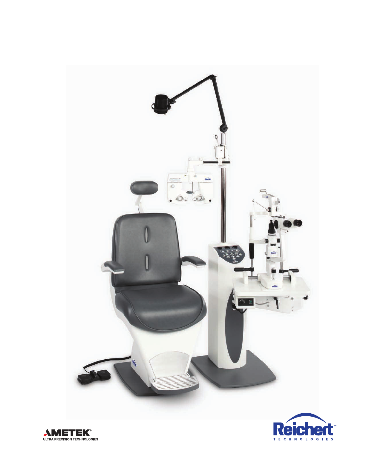
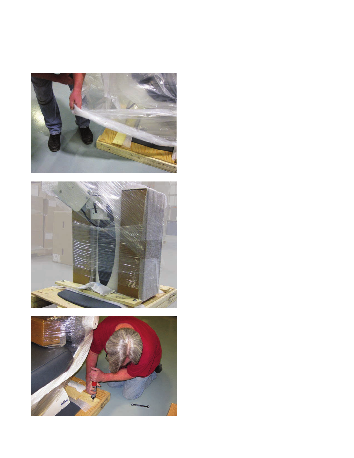
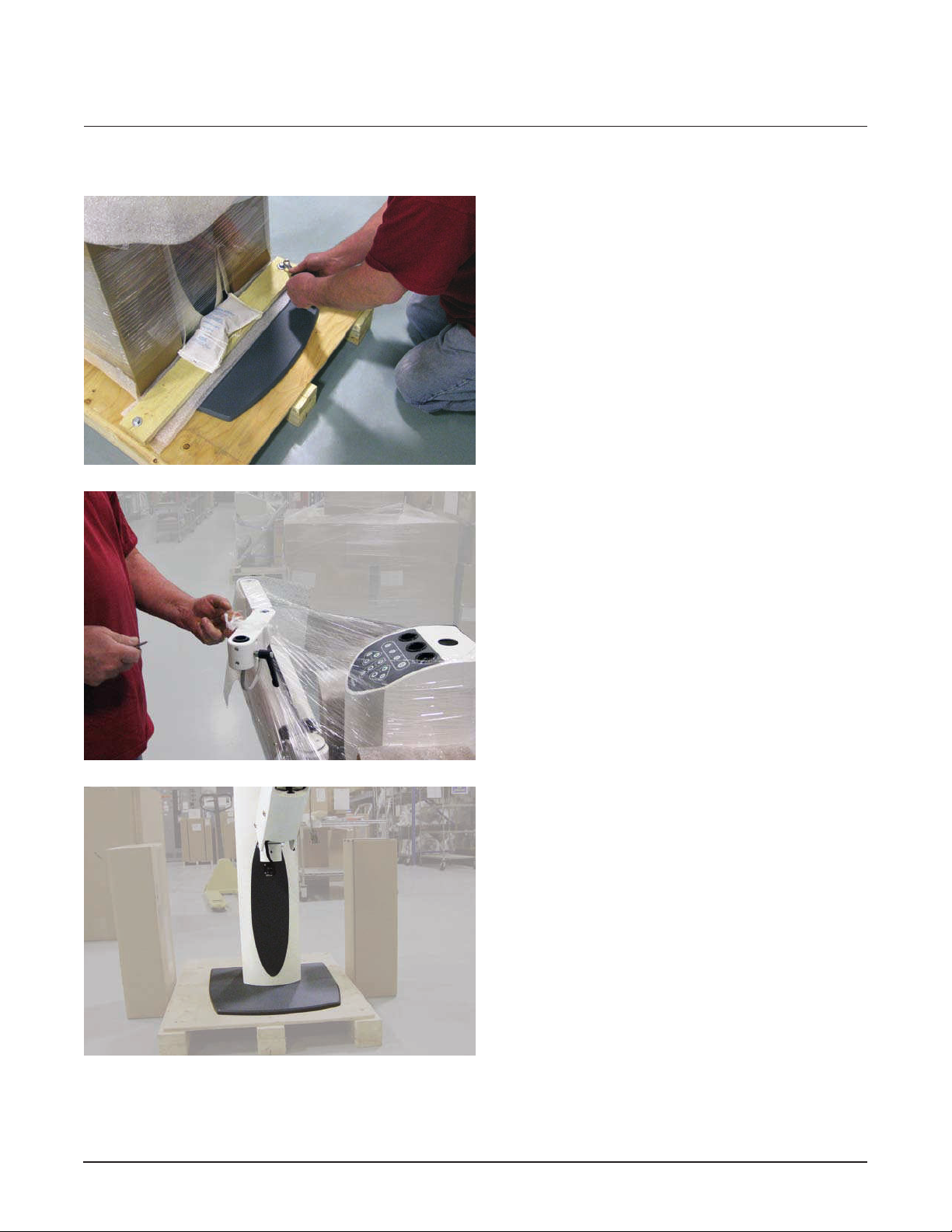
Unpacking ............................................................................................................................... 5-10
Contents of Packaging ............................................................................................................... 12
Features and Functions......................................................................................................... 11-13
Installation and Assembly...................................................................................................... 14-19
Lower Instrument Arm Assembly.......................................................................................... 14
Vertical Post Assembly ......................................................................................................... 15
Optional Third Arm Installation ............................................................................................. 16
Refractor Arm Assembly....................................................................................................... 16
Overhead Lamp Assembly ................................................................................................... 17
Lower Instrument Arm .................................................................................................... 18
Counterbalance Adjustment ........................................................................................... 18
Refractor Arm ................................................................................................................. 18
Counterbalance Adjustment ........................................................................................... 18
Chair and Stand Set-Up ....................................................................................................... 19
Operation.................................................................................................................................... 19
Lower Instrument Arm .......................................................................................................... 19
Control Panel........................................................................................................................ 20
Main ON/OFF Switch...................................................................................................... 20
Chair UP/DOWN Switch ................................................................................................. 20
Lower Instrument Arm Outlet Switch.............................................................................. 20
Chart Projector Outlet Switch ......................................................................................... 20
Accessory Outlet Switches............................................................................................. 20
Charging Wells ............................................................................................................... 20
Overhead Lamp ON/OFF Intensity Controls .................................................................. 21
Corded Instrument Voltage Selector............................................................................... 21
Overhead Lamp.............................................................................................................. 21
Chair Operation .............................................................................................................. 21
Maintenance............................................................................................................................... 23
Cleaning ............................................................................................................................... 23
Troubleshooting .......................................................................................................................... 23
Accessories................................................................................................................................ 23
Specifications ............................................................................................................................. 24
Storage and Transportation ........................................................................................................ 24
Disposal...................................................................................................................................... 24
Warranty..................................................................................................................................... 25
Notes..................................................................................................................................... 26-27

4 Endurance Tilt Chair and Stand User’s Guide 15250-101 REV-A
Warnings and Cautions
WARNING: AN INSTRUCTION THAT DRAWS ATTENTION TO RISK OF INJURY OR DEATH.
WARNING: DO NOT REMOVE OR DEFEAT THE EARTH GROUND CONNECTION ON THE ENDURANCE
TILT CHAIR AND STAND POWER INPUT CONNECTOR OR THE UNIT’S POWER CORD. DAMAGE TO THE
ENDURANCE TILT CHAIR AND STAND AND OR INJURY TO THE OPERATOR MAY OCCUR.
WARNING: THE ENDURANCE TILT CHAIR AND STAND SHOULD BE USED IN STRICT ACCORDANCE WITH
THE INSTRUCTIONS OUTLINED IN THIS USER’S GUIDE. THE SAFETY OF THE OPERATOR AND THE PER-
FORMANCE OF THE INSTRUMENT CANNOT BE GUARANTEED IF USED IN A MANNER NOT SPECIFIED
BY REICHERT OPHTHALMIC INSTRUMENTS.
WARNING: DISCONNECT POWER TO THE UNIT BEFORE OPENING ANY OF THE COVERS ON THE CHAIR
AND STAND.
WARNING: TO REDUCE THE RISK OF STATIC SHOCK, DO NOT TOUCH THE OVERHEAD LAMP AND
PATIENT AT THE SAME TIME.
CAUTION: AN INSTRUCTION THAT DRAWS ATTENTION TO THE RISK OF DAMAGE TO THE PRODUCT.
CAUTION: IN ORDER TO ENSURE THAT CORRECT OPERATION OF THE ENDURANCE TILT CHAIR AND
STAND IS MAINTAINED, ANY REPAIR OR SERVICE MUST BE PERFORMED BY EXPERIENCED PERSON-
NEL THAT ARE TRAINED BY REICHERT OPHTHALMIC INSTRUMENTS.
CAUTION: THE INTERNAL CIRCUITRY OF THE ENDURANCE TILT CHAIR AND STAND CONTAINS ELEC-
TROSTATIC DISCHARGE SENSITIVE DEVICES (ESDS). SUCH COMPONENTS MAY BE SENSITIVE TO HIGH
VOLTAGES PRODUCED BY STATIC CHARGES FROM THE HUMAN BODY. DO NOT REMOVE ANY OF THE
COVERS OF THE ENDURANCE TILT CHAIR AND STAND WITHOUT TAKING PROPER PRECAUTIONS OR
DAMAGE TO THE UNIT MAY OCCUR.
CAUTION: DO NOT USE SOLVENTS OR STRONG CLEANING SOLUTIONS ON ANY PART OF THE
ENDURANCE TILT CHAIR AND STAND OR DAMAGE TO THE UNIT MAY OCCUR.
CAUTION: DO NOT RAISE AND LOWER THE CHAIR EXCESSIVELY. CONSTANT RAISING AND
LOWERING OF THE CHAIR MAY CAUSE EXCESSIVE WEAR TO THE UNIT.
Symbol Information
The following symbols appear on the instrument:
CAUTION: Indicates that important operating and maintenance instructions are included in the
User’s Guide.
WARNING: The lightning bolt with the arrowhead symbol within an equilateral triangle is intended
to alert the user to the presence of” “dangerous voltage” within the unit’s enclosure that may be of
sufficient magnitude to constitute a risk of electrical shock.
Alternating Current – Indicates the instrument operates on alternating current.
Consult Instructions for Use – Indicates that important operating and maintenance instructions
are included in the User’s Guide.
Warnings and Cautions
Symbol Information
[REF] Catalog Number Date of Manufacture
I O ON/OFF
Hot Surface Hazard Warning
Type B-Class 1 Product Symbol Consult Instructions for Use
Waste of Electrical and Electronic Equipment

5
Endurance Tilt Chair and Stand User’s Guide 15250-101 REV-A
Congratulations on the purchase of your new Endurance Tilt Chair and Stand.
This User’s Guide is designed as a training and reference manual for operation, maintenance, and
troubleshooting. We recommend that you read it carefully prior to use and follow the instructions in the
guide to ensure optimum performance of your new products.
Please retain this manual for future reference and to share with other users. Additional copies can be
obtained from your authorized Reichert dealer or from the Reichert Customer Service department.
Contact information is provided at the end of this guide.
Unpacking
Unpacking the Endurance Tilt Chair
Introduction
1. Remove the plastic banding from the top of
the box.

6 Endurance Tilt Chair and Stand User’s Guide 15250-101 REV-A
3. Lift the carton off the chair.
4. Using a 14 mm wrench, remove the large
screws on the board at the front of the chair.
Unpacking
Unpacking the Endurance Tilt Chair
2. Remove the six screws (three each on
opposite sides of the box) that secure the
carton to the pallet.

7
Endurance Tilt Chair and Stand User’s Guide 15250-101 REV-A
Unpacking (continued)
5. Remove the remaining packing materials from
the chair. Retain the box with additional parts
for set-up. Carefully slide the chair off the pallet.
1. Remove the plastic banding straps from the
shipping carton.
Unpacking the Endurance Stand

8 Endurance Tilt Chair and Stand User’s Guide 15250-101 REV-A
2. Remove the six screws (three each on opposite
sides of the box) that secure the carton to the
pallet.
Unpacking (continued)
3. Lift the carton off the stand.
5. Cut the wire ties that secure the pole for the
stand inside the box and remove it.

9
Endurance Tilt Chair and Stand User’s Guide 15250-101 REV-A
Unpacking (continued)
6. The plastic covering on the stand is secured
with staples.Carefully pull away the plastic
wrap.
8. Remove the boards that secure the base of
the stand to the pallet.
7. The stand is packed with the lower arm
mounted and two boxes of parts.

10 Endurance Tilt Chair and Stand User’s Guide 15250-101 REV-A
9. Using a 14 mm wrench remove the large
screws that secure the board at the front of
the pallet.
Unpacking (continued)
10. Remove the plastic wrap from the stand
and boxes.
11. Remove the boxes from the stand and
carefully slide the stand off the pallet.
Retain the boxes with additional parts
for set-up.

11
Endurance Tilt Chair and Stand User’s Guide 15250-101 REV-A
Features and Functions
Contents
The items listed below should be included in the Endurance Tilt Chair and Stand packaging containers.
If any of these items are missing, please contact Reichert Customer Service.
•AdvantagePlusChair(P/N15250)
•FootSwitchAssembly(P/N15250-002-001)
•StandBaseWithControlPanelandChargingWells(P/N15253)•LowerInstrumentArm(P/N15257)
•OverheadLampAssembly(P/N15253-002-021)•OverheadLampBulb(P/N15253-002-022)
•RefractorArm(P/N15256)•LampCable(P/N15253-002-013)•SpareFuses•User’sGuide(P/N15250-101)Overhead Lamp Assembly
Vertical Mounting Post
Refractor Arm
Stand Base with Control
Panel and Charging Wells
Lower Instrument Arm
Chair
Foot Switch

12 Endurance Tilt Chair and Stand User’s Guide 15250-101 REV-A
Features and Functions
Contents of Stand Accessory Boxes
Box 1
A. Overhead Lamp Assembly
B. Power Cord for Stand
C. Lamp Cord
D. Slit Lamp Arm Wrench
E. Collar for Base of Pole
F. Armlock Screw Handle
G. Phoropter Safety Collar
H. Lamp Collar
I. 5/23 Phoropter Hex Key
J. Spare Fuse
K. 3/4 Needle Thrust Bearing
Box 2
L. Phoropter Bearing Collar
M. Phoropter Arm Assembly
N. Phoropter Mounting Pole
Box 1
O. Foot Switch
P. Spare Fuse
Q. Power Cord
R. Chair & Stand Connector
Contents of Chair Accessory Box
A
B
C
E
F
D
G H I J K
L
M
N
R
O
P
Q

13
Endurance Tilt Chair and Stand User’s Guide 15250-101 REV-A
Features and Functions (continued)
Hanger for Bios
Chart Projector
Outlet
Accessory Outlet
Main Power Fuse
ON/OFF Switch
Power Cord Inlet Chair Control
24 VAC/VOC Max
5A Max
Corded Instrument
Binding Posts
Voltage Limit Switch
Chair Control
12 V 1ma
Auxiliary
Outlets
The two outlets to the right
are always powered on.
Power to the two outlets
to the left is controlled by
membrane panel switches.
Hand Instrument
Charging Wells
Chair UP/DOWN
Switches Auto Down Switch
ON/OFF Button for Power
to Membrane Panel
Overhead Lamp
Brightness Control Switches
Overhead Lamp
ON/OFF Switch
Charge Indicators
Lower Arm
(Slit Lamp) ON/OFF
Switch & LED
Voltage Selector
Switches & Scale:
Controls voltage to
corded instrument
binding posts on
rear panel
Chart Projector
ON/OFF Switch & LED
Control Panel
Accessory ON/OFF switch

14 Endurance Tilt Chair and Stand User’s Guide 15250-101 REV-A
Installation And Assembly
WARNING: TO REDUCE THE RISK OF ELECTRICAL SHOCK, DO NOT CONNECT THE UNIT TO A POWER SOURCE
UNTIL THE ASSEMBLY PROCESS IS COMPLETED.
Before you begin the assembly process:
1. Be sure the floor is level.
2. Be sure your stand is correctly positioned in the desired location.
Lower Instrument Arm
1. Connect the lower instrument arm power cord to the stand.
2. Install the front brake handle.
A. Drag set screw (5/32 allen key)
B. Lower arm power cord
C. The lower instrument arm is pre-installed
on the stand. The arm can be removed
and replaced with one screw located at
the front of the stand.
D. Lock release lever
E. Power cord to slit lamp
A
B
D
E
F. Front brake handle
F
C

15
Endurance Tilt Chair and Stand User’s Guide 15250-101 REV-A
Installation And Assembly (continued)
3. Place the needle bearing assembly on top of the arm port before installing the slit lamp.
4. Using the 5/32 allen key, adjust the instrument leveling set screws as needed to level the table
when installing the slit lamp. There are six screws located in the front and on each side of the
slit lamp port.
Installing the Mounting Pole
1. Open the back of the lower section of the stand by removing the six screws that hold the panel
in place. The back panel is notched at the bottom so slide it up and out of position to remove it.
2. Insert the pole into the opening at the top of the stand and align the notch at the bottom of the
pole with the pins at the base of the pole support.
G. Slit lamp leveling set screws
H. Ø ¾ needle bearing assembly
G
G
H
A. Rod Notch
B. Pins
A
B
B

16 Endurance Tilt Chair and Stand User’s Guide 15250-101 REV-A
3. Slide the white rod collar down to the base of the pole and tighten the allen key to hold it
in place.
Optional Third Arm Installation
1. Slide the safety collar down the pole to the desired position for the Third Arm and tighten the
allen key to secure it in place.
2. Slide the Third Arm down over the vertical post to the desired location and tighten the locking
ring allen screw.
3. Remove the cover over the auxiliary power panel and plug the the Third Arm power cord into
the outlet labeled ACC.
Refractor Arm Assembly
1. Slide the safety collar for the Refractor Arm down the mounting pole into the desired position
and tighten the allen key with the 5/32 wrench.
2. Slide the Refractor Arm (with the lock ring to the bottom) down the vertical post to the desired
position and tighten the lock handle to secure it in place.
3. Slide the white refractor bearing collar down the pole until it is in place over the refractor arm
mount.
4. Slide the refractor mounting bar into the Refractor Arm and tighten in place.
5. Any exposed wires from auxiliary instruments can be concealed in the refractor arm by pulling
up the wire cover strip, feeding the wire into the slot in the arm, and replacing the cover strip.
Installation And Assembly (continued)
C. Rod collar and key
A. Refractor arm safety collar
B. Refractor arm lock handle
C. Refractor mounting bar
D. Wire cover strip
A
B
C
C
D

17
Endurance Tilt Chair and Stand User’s Guide 15250-101 REV-A
Installation And Assembly (continued)
Overhead Lamp Assembly
1. Feed the lamp cord through the mounting pole. Fit the rod cap with lamp wire extended into the
top of the pole.
2. Connect the lamp cord to the keyed plug in the stand
3. Connect the lamp assembly to the lamp plug at the top of the pole.
A. Keyed lamp plug
B. Lamp cord plugged in
AB

18 Endurance Tilt Chair and Stand User’s Guide 15250-101 REV-A
Installation And Assembly (continued)
Counterbalancing of Lower Instrument Arm
WARNING: THE LOWER INSTRUMENT ARM CAN RISE ABRUPTLY IF THE LOCK RELEASE LEVER IS
PRESSED WHEN THE ARM IS IN THE DOWN POSITION AND IS NOT BALANCED. DO NOT LEAVE
THE ARM IN THE DOWN POSITION WITHOUT AN INSTRUMENT INSTALLED ON THE ARM OR
ACCIDENTAL MOVEMENT OF THE ARM MAY OCCUR, POTENTIALLY CAUSING INJURY.
The counterbalance mechanism on the lower instrument arm is a compression spring.
The counterbalance is factory set to 30 lbs. Use the hex wrench provided to adjust the tension on the
compression spring.
Counterbalancing of Refractor Arm
WARNING: THE REFRACTOR ARM CAN RISE ABRUPTLY IF THE LOCKING HANDLE IS RELEASED, WHEN
THE ARM HAS BEEN LEFT IN A DOWNWARD POSITION, AND IT HAS NOT BEEN BALANCED.
DO NOT LOCK THE ARM IN THE LOWER POSITION WITHOUT A REFRACTOR INSTALLED OR
ACCIDENTAL MOVEMENT OF THE ARM MAY OCCUR, POTENTIALLY CAUSING INJURY.
The counterbalance mechanism on the refractor arm is a compression spring. The counterbalance
is factory set to 10 lbs. Adjust the tension on the spring by using a flat head screwdriver.

19
Endurance Tilt Chair and Stand User’s Guide 15250-101 REV-A
Chair Set-Up
1. Connect the power cords to the stand and the chair and plug them into outlets.
2. Connect the Chair Power/Control Cord to the stand and the chair.
3. Connector the Foot Switch to the connector on the chair base.
Lower Instrument Arm
There are three locking handles on the lower instrument arm: one that controls the position of the lower section
of the arm, one that controls movement of the upper section of the arm, and one that tightens and loosens the
slit lamp table. Turn the locking handles to the right to tighten and hold the arm in position, and turn them coun-
terclockwise to loosen the handle and move the arm into a different position.
Press the release latch in the upper section of the arm to raise and lower the entire arm.
Refractor Arm
The position of the refractor arm can be raised or lowered
by releasing the locking handle. Push the handle away from
yourself to release it. Pull the handle toward yourself to lock
the refractor arm in place.
Installation And Assembly (continued)
A. Locking handle of the lower
section of the arm (not shown)
B. The chair moves up and down
from this pivot point.
C. Lower arm release latch
D. Locking handle for the upper
section of the arm
E. Slit Lamp table locking handle
A
C
D
E
B
Operation
A. Refractor arm locking handle
A

20 Endurance Tilt Chair and Stand User’s Guide 15250-101 REV-A
Operation (continued)
Control Panel
The Control Panel (See page 15 for Control Panel diagram) contains all of the
electrical controls except
(1) the Main Power ON/OFF Switch, (2) a secondary Chair UP/DOWN Switch and
(3) the Lower Arm Vertical Motion Switch.
Main ON/OFF Switch
Located on the bottom left corner of the back of the stand the Main ON/OFF
Switch controls the electric power for the entire stand. This switch is a rocker type.
Press the side with the straight line “I” to turn the stand ON. You will hear
a beep that indicates the stand is energized. Press the side with the circle “O”
to turn the stand OFF.
Chair UP/DOWN Switch
Press and hold the UP Arrow to raise the chair. Press and hold the DOWN Arrow to lower the chair.
Press the AUTO button for Auto-Down mode.
Note: The Chair can be operated from the Foot-Switch or Lower Arm Switch as well.
Lower Instrument Arm ON/OFF Switch
The S.L. Switch is a push type on-off switch to control the electricity to the outlet on the Lower Instrument
Arm. If the switch is off, depressing it once will turn it on and apply power to the outlet on the Lower
Instrument Arm. If the switch is on, depressing it once will turn the switch off. An LED just to the left of
the switch illuminates to indicate the switch is on.
Chart Projector ON/OFF Switch
The C.P. Switch is a push type on-off button. It controls the electricity to the C.P. Outlet on the lower left of
the Auxiliary Power Panel. If the switch is OFF, pressing the switch once will turn it on. If the switch is on,
pressing the switch once will turn it off. An LED just to the left of the switch lights up when the switch is ON.
Accessory ON/OFF Switch
The ACC Switch is a push type on-off switch. It controls the electricity to the ACC Outlet on the left of the
Power Input Panel when facing the back of the stand. If the switch is OFF, pressing the switch once will
turn it ON. If the switch is ON, pressing the switch once will turn it OFF. An LED just to the left of the switch
lights up when the switch is ON.
Charging Wells
CAUTION: DO NOT ATTEMPT TO STORE HANDLES THAT USE ONLY ALKALINE BATTERIES IN THE CHARGING
WELLS OR DAMAGE TO THE CHARGING WELLS OR HAND-HELD INSTRUMENTS MAY OCCUR.
The Charging Wells are designed for hand-held instruments with a rechargeable battery. The Charging
Wells will charge instrument batteries as long as the instrument handle is fully inserted in the well.
There is a Charge Indicator Light beneath each well that indicates an instrument is properly seated
and charging.
Note: Your hand-held instruments must be turned OFF prior to placing them in the Charging Well.
Additionally, the Stand Main ON/OFF Switch must be ON for the instrument batteries to charge.
Table of contents
Other Ametek Medical Equipment manuals