AMF-BRUNS LINEARLIFT AL1 User manual

Operating Instructions
www.amf-bruns.de
LINEAR LIFT AL1


Foreword
Linear Lift AL1 Page 3 of 72
Foreword
Dear Reader,
these Operating Instructions serve to provide all information required
for the safe use of the linear lift.
The linear lift is designed and constructed in accordance with state
of the art technology and recognised safety standards. Persons and
materials can however be endangered, as not all danger areas can
be eliminated if the functional capability is to be maintained. Ac-
cidents caused by these dangers can however be prevented by
strictly observing these Operating Instructions. Over and above this,
the operational efficiency of your linear lift can be used to the full and
unnecessary faults can be prevented.
After reading these Operating Instructions for the first time, keep
them in a safe place for future reference over the entire lifetime of
the linear lift. Chapter 12 of these Operating Instructions contains an
Inspection Log that is required by the technical expert for his / her
annual inspection of the linear lift.
If you sell the linear lift, hand these Operating Instructions over to the
new owner.
All details, figures and dimensions contained in these Operating In-
structions are non-binding. No claims in any form can be derived
from these.
This document must not be reproduced or duplicated, in full or in
part, without the prior, written permission of the manufacturer.
The linear lift must never be converted or modified in any way, wit-
hout seeking the prior, written permission of the manufacturer. The
manufacturer will not be held responsible in any way whatsoever if
conversions or modifications are carried out without authorisation.
Use only original spare parts or spare parts which have been appro-
ved of by the manufacturer. If spare parts other than these are
used, this can have a negative effect on the specified characteris-
tics, the functionality and safety of the linear lift. Using non-original or
unauthorised spare parts will render the guarantee null and void.
Contact our customer service department to order spare parts or
accessories. The spare parts catalogue can be found in the service
section of our Internet site (see Chapter 15, page 70).

Foreword
Page 4 of 72 Linear Lift AL1
Explanation of symbols and signs
To improve understanding, the following conventions should be met
for these Operating Instructions:
1.
The following conventions are used to highlight important informati-
on:
DANGER!
y warns of a situation of immediate danger, which will lead to seve-
re or fatal injuries if not avoided.
W
ARNING!
y warns of a potentially dangerous situation, which will lead to se-
vere or fatal injuries if not avoided.
CAUTION!
y warns of a potentially dangerous situation, which will lead to slight
or minor injuries or material damage if not avoided.
A
TTENTION!
...warns of a potentially dangerous situation, which can cause mate-
rial damage, if not avoided.
...contains general notes and useful information.
...gives a reference to important information in other sections and
documents.
2.
Some text passages serve a special purpose. These are identified
as follows:
y Lists.
Instructional text, e.g. a sequence of activities.

Foreword
Linear Lift AL1 Page 5 of 72
3.
Meaning of directions:
If directions are given in the text (in front of, front, behind, rear, right,
left), these directions relate to the normal direction of travel of the
vehicle.

Contents
Page 6 of 72 Linear Lift AL1
Contents
1 Safety ..............................................................................8
1.1 Proper Use........................................................................... 8
1.2 Improper Use....................................................................... 9
1.3 Personnel Requirements...................................................... 9
1.4 Product Monitoring .............................................................10
1.5 Danger Zone.......................................................................10
1.6 Safety Devices .................................................................... 11
1.6.1 Guardrails ................................................................. 11
1.6.2 Roll-off guard............................................................ 11
1.7 Safety and Accident Prevention Regulations....................... 11
2 Description .................................................................... 13
2.1 Layout and Function ...........................................................13
2.1.1 Platform....................................................................14
2.1.2 Transfer plate ...........................................................16
2.1.3 Lifting unit .................................................................16
2.1.4 Hydraulic system ...................................................... 17
2.2 Rating Plate......................................................................... 17
2.3 Technical Data ....................................................................18
2.4 Operating Controls..............................................................19
3 Transportation............................................................... 21
4 Installation / Commissioning ......................................... 21
5 Operation...................................................................... 22
5.1 Safety Regulations for Operation ....................................... 22
5.2 Switching OFF in an Emergency (Emergency Stop)........... 24
5.3 Switching the linear lift ON ................................................. 24
5.4 Switching the linear lift OFF ................................................ 24
5.5 Lowering the Platform........................................................ 25
5.6 Raising the Platform........................................................... 27
6 Emergency Mode ......................................................... 30
6.1 Raising in the Emergency Mode ........................................ 30
6.2 Lowering in the Emergency Mode ..................................... 32
7 Maintenance and Repair .............................................. 34
7.1 Safety Regulations for Maintenance and Repair ................ 34
7.2 Routine Maintenance Work................................................ 35
7.2.1 Service life of components ...................................... 35
7.2.2 Maintenance schedule ............................................ 35
7.2.3 Maintenance record ................................................ 35
7.3 Functional Test of the Safety Devices ................................ 36
7.4 Inspection of the Hydraulic Hoses. .................................... 36

Contents
Linear Lift AL1 Page 7 of 72
7.5 Yearly Inspection................................................................36
7.6 Maintenance and Inspection Record ................................. 37
8 De-Commissioning and Conservation ..........................38
9 Disposal.........................................................................38
10 Faults and Troubleshooting ..........................................39
11 Fine Adjustments ..........................................................42
11.1 Roll-Off Guard ....................................................................42
11.2 Transfer Plate.....................................................................43
11.3 Split Platform: Adjusting the Platform Segments ................44
11.4 Elbow Joints.......................................................................45
11.5 Adjusting the Panorama Platform.......................................48
11.6 Arrester Hooks...................................................................50
11.7 Micro-Switches .................................................................. 51
12 Inspection Log...............................................................56
12.1 Inspection Log Master Data Sheet..................................... 57
12.2 Inspection List ....................................................................58
12.3 Inspection Results..............................................................59
13 Electrical Circuit Diagrams ...........................................67
14 Hydraulic Circuit Diagram .............................................69
15 Customer Service ......................................................... 70
16 Declaration of Conformity..............................................71

Safety
Page 8 of 72 Linear Lift AL1
1 Safety
CAUTION!
There are a number of risks of suffering personal injury and material
damage involved in the operation and maintenance of the linear lift.
Therefore:
y It is imperative, that these Operating Instructions are read
thoroughly before operating your linear lift. Always observe the
notes and information contained therein, in particular the safet
y
instructions.
y If these Operating Instructions or parts thereof are lost
or become illegible, please request a new copy from the manu-
facturer.
Prerequisite to the safe handling and trouble-free operation of the li-
near lift is a thorough knowledge of the applicable safety information
and the safety regulations.
It is therefore imperative that this Chapter is read thoroughly before
operating the linear lift and that the instructions and warnings herein
are strictly observed. The safety information and warnings, given at
the appropriate places in the following Chapters, must also be
strictly observed. The manufacturer will not be held responsible if
safety information and warnings are not observed.
In addition to the information given in these Operating Instructions,
local legislative regulations must be taken into consideration, in par-
ticular those regarding safety and accident prevention.
1.1 Proper Use
The linear lift must only be used for lifting and lowering disabled per-
sons seated in wheelchairs or empty wheelchairs. By using the line-
ar lift, persons can be embarked into or disembarked from the ve-
hicle to which it is fitted.
When doing so, the linear lift is operated by an accompanying per-
son who does not ride on the platform. Unless of course the person
in the wheelchair is also the driver of the vehicle.
Proper use also includes strictly adhering to the information given in
these Operating Instructions.

Safet
y
Linear Lift AL1 Page 9 of 72
W
ARNING!
If the linear lift is used for any other purpose than that described
above, this may result in dangerous situations for persons or materi-
al damage being caused.
Therefore:
y Only use the linear lift for the purpose for which it was intended.
y Always adhere to information given in these Operating Instruc-
tions.
y Do not use the linear lift
f
or any other purposes, particularly those
given in Section 1.2. These are deemed to be improper use.
1.2 Improper Use
Any type of use, other than that mentioned in section 1.1 is deemed
to be improper use.
The linear lift is deemed to be improperly used if for example:
y for lifting and lowering goods (exception: empty wheelchairs),
y for lifting and lowering persons who are not seated in a
wheelchair,
y it is used as a link bridge or
y it is used by incompetent persons.
1.3 Personnel Requirements
The linear lift must only be handled by persons who:
y who are of legal age,
y have been instructed in how to operate the linear lift,
y have read and understood these Operating Instructions,
y have proven their ability to operate the linear lift to the vehicle's
owner,
y have been expressly assigned by the vehicle's owner to operate
the linear lift,
y have the technical knowledge to operate the wheelchair's brakes
and switch the motors of electrically driven wheelchairs ON and
OFF and
y who are in a position to adapt themselves to the particular beha-
viour and needs of disabled persons.
Transportation, installation, commissioning, maintenance, repair,
fault finding and disposal of the linear lift must only be carried out by
persons with the corresponding technical training and experience.

Safety
Page 10 of 72 Linear Lift AL1
1.4 Product Monitoring
Please contact AMF-Bruns GmbH & Co. KG immediately if faults or
problems are encountered when operating your linear lift or if ac-
cidents or "near-misses" occur.
AMF-Bruns will effect a solution to the problem with your help and
the knowledge gained will flow into future projects.
NOTE
Guarantee work on the linear lift must only be carried out with the
prior agreement of AMF-Bruns GmbH & Co. KG.
The costs of such work will not be accepted by AMF-Bruns without
prior agreement.
If damage occurs, AMF-Bruns GmbH & Co. KG will require the serial
number, the year built as well as a description of the damage and if
possible, a photograph of the damage.
1.5 Danger Zone
The danger zone is any area on, below or within the range of mo-
vement of the platform, as well as around the drive and carrier sys-
tem, in which persons are exposed to the risk of injury or damage to
health.
CAUTION!
Risk of injury through movements of the linear lift.
There are a number of risks of personal injury if standing within the
danger zone.
Therefore:
y Only operate the linear lift if there are no persons standing within
the danger zone.
y Keep the danger zone under observation and stop the linear lift if
any persons enter the danger zone.

Safet
y
Linear Lift AL1 Page 11 of 72
1.6 Safety Devices
1.6.1 Guardrails
The guardrails fold down to the horizontal position, together with the
platform, when the linear lift’s platform is lowered from the stowed
position to the deployed position. They provide support for the
passenger and increase the sense of security when the platform is
being raised or lowered.
1.6.2 Roll-off guard
A roll-off guard is fitted to the side of the platform furthest from the
vehicle. When the platform is raised, the roll-off guard rises automa-
tically and latches in position. This prevents the passenger in their
wheelchair from rolling off the platform.
1.7 Safety and Accident Prevention
Regulations
Adhere to the following notes in order to prevent personal injuries
and material damage. Also adhere also to the relevant safety and
accident prevention regulations laid down by the trade associations.
y The linear lift must only be operated if all safety and protective
devices are correctly fitted (see Section 1.6, page 11). Such de-
vices must only be removed in order to enable maintenance and
repair work to be carried out. All safety and protective devices
must be replaced immediately after such work has been comple-
ted. If they are not replaced correctly, there is a high risk of injury.
y The linear lift must only be used for the purpose for which it is in-
tended, otherwise dangerous situations, with resultant injuries,
may occur (Proper use: see Section 1.1, page 8).
y The owner is responsible for ensuring that proper use is adhered
to, in particular that the linear lift is only operated by authorised
persons.
y If the linear lift is used commercially or as a public utility, the ow-
ner must ensure that operating personnel are familiar with the
operation of the linear lift under all operating conditions by giving
training and familiarisation courses.
y In order to be able to transport wheelchair-bound persons, the
vehicle must be fitted with the necessary special equipment in
accordance with DIN EN 75078. To prevent dangers in road traf-
fic, the linear lift must be equipped with warning lights or warning
markings.

Safety
Page 12 of 72 Linear Lift AL1
y A number of dangers may arise during operation due to adverse
lighting conditions. The owner is obliges to equip the vehicle or
the linear lift with the corresponding lighting fixtures.
y It is forbidden for persons to ride on the platform id they are not
in a wheelchair.
y Proper use of the linear lift also includes adherence to the spe-
cified maintenance and repair work, in particular strict adherence
to the maintenance intervals. If such work is not carried out,
trouble-free operation can not be guaranteed. Risks of personal
injury and material damage can occur. We recommend that
maintenance records be kept.
y If the linear lift is used commercially or as a public utility, it must
be inspected by a technical expert at intervals of not more than 1
year after commissioning. During inspection, faults affecting the
safety should be systematically identified and remedial action ta-
ken (see "Inspection Log", page 56).
y Do not deposit any items on the linear lift. Persons can suffer inju-
ries if such items fall off the platform.
y The linear lift must not be operated in a faulty condition, as seri-
ous injuries may be caused by this. If faults occur, do not use the
linear lift until repairs have been effected.
y Switch the linear lift OFF before carrying out maintenance or re-
pair work, this includes cleaning work. Make certain that no other
person can switch the linear lift ON (e.g. by disconnecting the
starter battery). If this is not done, there is a risk of injury.
y Use only original spare parts or spare parts which have been ap-
proved of by the manufacturer. If non-original or unauthorised re-
placement parts are used, this will render the guarantee null and
void.
Description
Linear Lift AL1 Page 13 of 72
2 Description
Persons who are wheelchair-bound can be embarked into or
disembarked from a vehicle using the linear lift.
The main components of the linear lift are:
y the platform,
y the lifting unit with carrier arms, guardrails and floor anchorages,
y the hydraulic system and
y the operating controls.
The aim of this chapter is to illustrate the construction and function
of the linear lift. To this end, the individual assemblies and compo-
nents are described in the following sections.
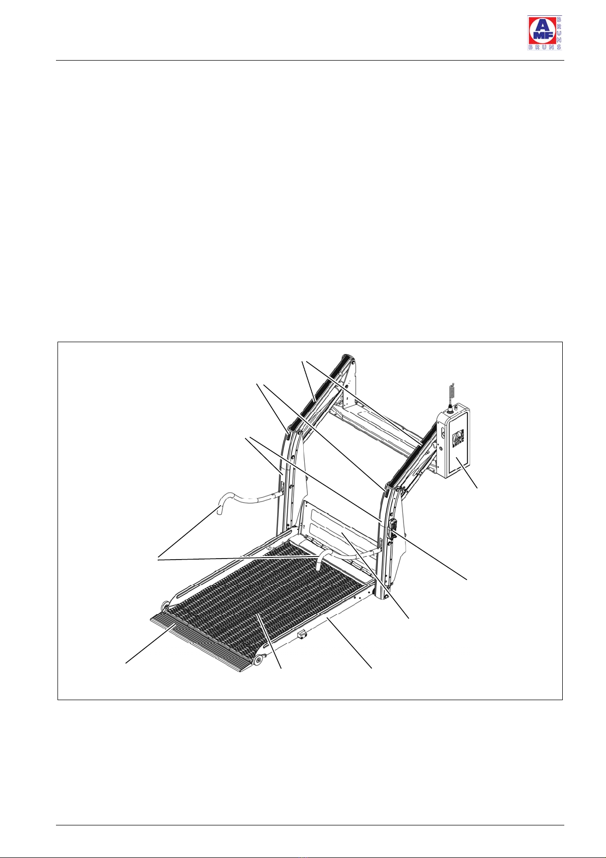
2.1 Layout and Function
Figure 1: linear lift AL1 Solid, Overview
Guardrails
Platform
Roll-off guard
Switch box with
hydraulic pump
Transfer plate
Carrier arms
Blinkers (optional)
Carrier struts
Remote control
Side roll-off guards
Description
Page 14 of 72 Linear Lift AL1
2.1.1 Platform
The platform has an anti-slip grating surface and is equipped with
side roll-off guards. These prevent the passenger’s wheelchair from
rolling off the side of the platform.
A roll-off guard is fitted to the side of the platform furthest from the
vehicle (see Figure 1, page 13). When the platform is lowered fully to
the ground, the roll-off guard folds down. This provides the passen-
ger in the wheelchair with easy access the platform. As soon as the
platform is raised from the ground, the roll-off guard rises and lat-
ches in position. This prevents the passenger’s wheelchair from rol-
ling backwards off the platform.
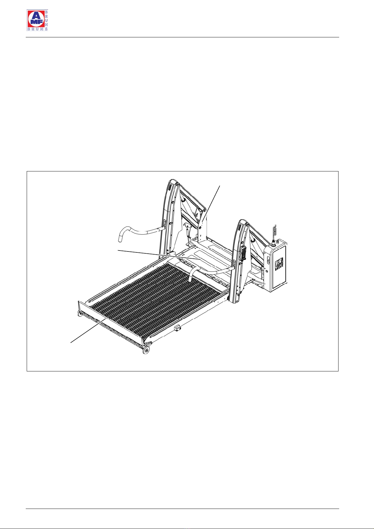
Figure 2: linear lift AL1 Solid, Embarkation and Disembarkation Level
The linear lift AL1 Solid has a one-piece platform. The platform of the
linear lift AL1 Panorama is made up of two sections such that it is
shortened when folded up to the stowed position.
Transfer plate
Roll-off guard
Floor anchorage
Description
Linear Lift AL1 Page 15 of 72
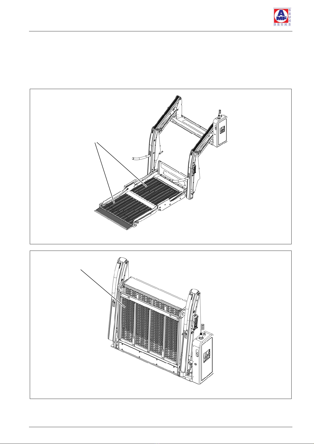
This enables a linear lift with a long platform to be installed in vehic-
les with restricted interior height. In addition to this, the driver has a
clear view through the rear window when driving. Over and above
this, the fact that a linear lift is installed in the vehicle can not be
seen from the outside (see Figure 3 and Figure 4).
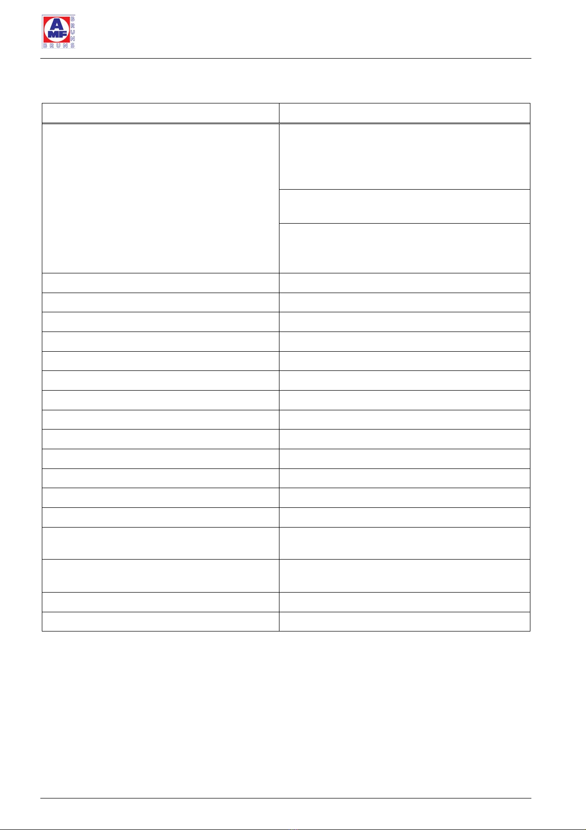
Figure 3: linear lift AL1 Panorama, Overview
Figure 4: linear lift AL1 Panorama, Stowed Position
Platform
Platform

Description
Page 16 of 72 Linear Lift AL1
The platform of the linear lift AL1 Split is split lengthwise. When it is
stowed in the driving position, the two halves of the platform separa-
te (see Figure 5). Because of this, it is possible to enter and leave
the vehicle by way of the door in which the linear lift is installed, even
though the linear lift is in the vertical, stowed position.
Figure 5: linear lift AL1 Split, Stowed Position
2.1.2 Transfer plate
A transfer plate is fitted to the linear lift. When the platform reaches
the same level as the vehicle’s floor when being raised (embark /
disembark level), the transfer plate closes the gap between platform
and vehicle. This ensures convenient, safe embarkation / disembar-
kation (see Figure 1, page 13 and Figure 2, page 14).
2.1.3 Lifting unit
The lifting unit represents the connection between platform and ve-
hicle. The lifting and lowering movements are carried out by four
carrier arms that are powered by hydraulic cylinders (see Figure 1,
page 13). The carrier arms act on carrier struts, to which the plat-
form and guardrails are attached. The platform and guardrails auto-
matically fold down on elbow joints actuated by the carrier arms
when the linear lift is lowered from its vertical position.
When the linear lift is raised to a level above the floor of the vehicle,
to the stowed position, the guardrails and platform are folded up to
Platform

Description
Linear Lift AL1 Page 17 of 72
the vertical, stowed position. Because of this, the linear lift takes up
a minimum of space in the vehicle (see Figure 5, page 16).
The carrier arms are connected to the vehicle by the floor anchora-
ges (see Figure 2, page 14).
2.1.4 Hydraulic system
The hydraulic system’s motor, pump and oil reservoir are located in
the switch box on the side of the linear lift (see Figure 1, page 13).
The operating voltage for the motor is supplied by the starter bat-
tery. The hydraulic cylinders that are powered by the pump are lo-
cated between the carrier arms.
The hydraulic system can be manually operated in an emergency.
2.2 Rating Plate
A rating plate, which contains the fundamental data, is attached to
the linear lift (see Figure 6). The rating plate is located on the floor
anchorage.
Figure 6: Rating Plate
Year of manufacture
Serial number
Designation
Manufacturer
Version
Load bearing
capability
Description
Page 18 of 72 Linear Lift AL1
2.3 Technical Data
Designation Linear Lift AL1
Type / Lifting platform Solid 1065
Solid 1130
Solid 1200
Solid 1380
Panorama 1200
Panorama 1400
Split 1085
Split 1085 S
Split 1300
Weight 133 kg ± 10
Permissible operating pressure 92 bar
Permissible number of persons on the platform max. 1 person in a wheelchair
Carrying capacity 400 kg
Lifting height 900 mm
Lifting speed 0.058 m*
Max. lowering speed 0.068 m*
Deploy speed 0.3 m*
Stow speed 0.3 m*
Operating / control voltage 12 V
Current consumption max. 60 A
Sound pressure emission < 78 dB(A)
Equipment suitable for use in the vehicle
Safeguard against the platform lowering inadver-
tently if leaks occur in the hydraulic pipelines
Burst pipe protection valve
(see Hydraulic Circuit Diagram)
Safeguard against excess hydraulic pressure Operating pressure 92 bar;
Response pressure 75/92 bar
Hydraulic oil Recommendation: ATF Dexron II, 1.4 litre
Appendix to the Inspection Log Electrical Circuit Diagram, Hydraulic Circuit Diagram

Description
Linear Lift AL1 Page 19 of 72
2.4 Operating Controls
Figure 7: Operating Controls on the Remote Control
Figure 8: Operating Controls on the Hydraulic Pump
3
2
5
1
4
6

Description
Page 20 of 72 Linear Lift AL1
Item Designation Function
1 Push-button
“UP”
Raises the platform from the ground to
the embarkation / disembarkation level.
Switches the remote control ON, if it
has switched OFF due to not being
used for a longer period of time.
2 Push-button
“DOWN”
Lowers the platform from the embarka-
tion / disembarkation level to the
ground.
3 Push-button
“UNFOLD”
Lowers the linear lift from the vertical,
stowed position.
4 Push-button
“FOLD”
Raises the linear lift to the vertical, sto-
wed position.
5 Battery isolation
switch
Interrupts the power supply to the hyd-
raulic pump motor.
6 Circuit breaker Trips when a fault occurs and renders
the remote control inoperative.
Other manuals for LINEARLIFT AL1
2
Table of contents
Other AMF-BRUNS Lifting System manuals

AMF-BRUNS
AMF-BRUNS LINEARLIFT AL1 User manual

AMF-BRUNS
AMF-BRUNS BSL 350 User manual

AMF-BRUNS
AMF-BRUNS K70 User manual

AMF-BRUNS
AMF-BRUNS BSL 350 User manual

AMF-BRUNS
AMF-BRUNS HUBMATIK K90 User manual

AMF-BRUNS
AMF-BRUNS K70 User manual

AMF-BRUNS
AMF-BRUNS BSL 350 User manual

AMF-BRUNS
AMF-BRUNS Easy-Flex-Ramp User manual

AMF-BRUNS
AMF-BRUNS Linearlift Series User manual


