AMG Systems Ltd. reserves the right to make changes to this document without
notice. The information herein is believed to be accurate. No responsibility is
assumed by AMG for its use.
Page 5of 7 AMG2783R-DR Instruction
Sheet D15232-00
Indicators
Power...................................................Green – unit powered
Off – no power applied to unit
Primary Opto Sync TX.........................Green - optical channel transmitting
Off - optical channel not transmitting
Primary Opto Sync RX ........................Green - optical channel receiving
Off - optical channel not receiving
Secondary Opto Sync TX....................Green - optical channel transmitting
Off - optical channel not transmitting
Secondary Opto Sync RX....................Green - optical channel receiving
Off - optical channel not receiving
Video Present CH1..............................Green – video signal present on video CH1 input BNC
Off – no video present on video CH1 input BNC
Video Present CH2..............................Green – video signal present on video CH2 input BNC
Off – no video present on video CH2 input BNC
Video Present CH3..............................Green – video signal present on video CH3 input BNC
Off – no video present on video CH3 input BNC
Video Present CH4..............................Green – video signal present on video CH4 input BNC
Off – no video present on video CH4 input BNC
Video Present CH5..............................Green – video signal present on video CH5 input BNC
Off – no video present on video CH5 input BNC
Video Present CH6..............................Green – video signal present on video CH6 input BNC
Off – no video present on video CH6 input BNC
Video Present CH7..............................Green – video signal present on video CH7 input BNC
Off – no video present on video CH7 input BNC
Video Present CH8..............................Green – video signal present on video CH8 input BNC
Off – no video present on video CH8 input BNC
Data Present TX ..................................Green – logic one present on the data input
Red – logic zero present on the data input
Off – tri-state off or no connection on the data input
This represents the data signals being transmitted on the optical fibre
Data Present RX..................................Green – logic one present on the corresponding data
output
Red – logic zero present on the data output
Off – tri-state off on the data output
This represents the data signals being received on the optical fibre
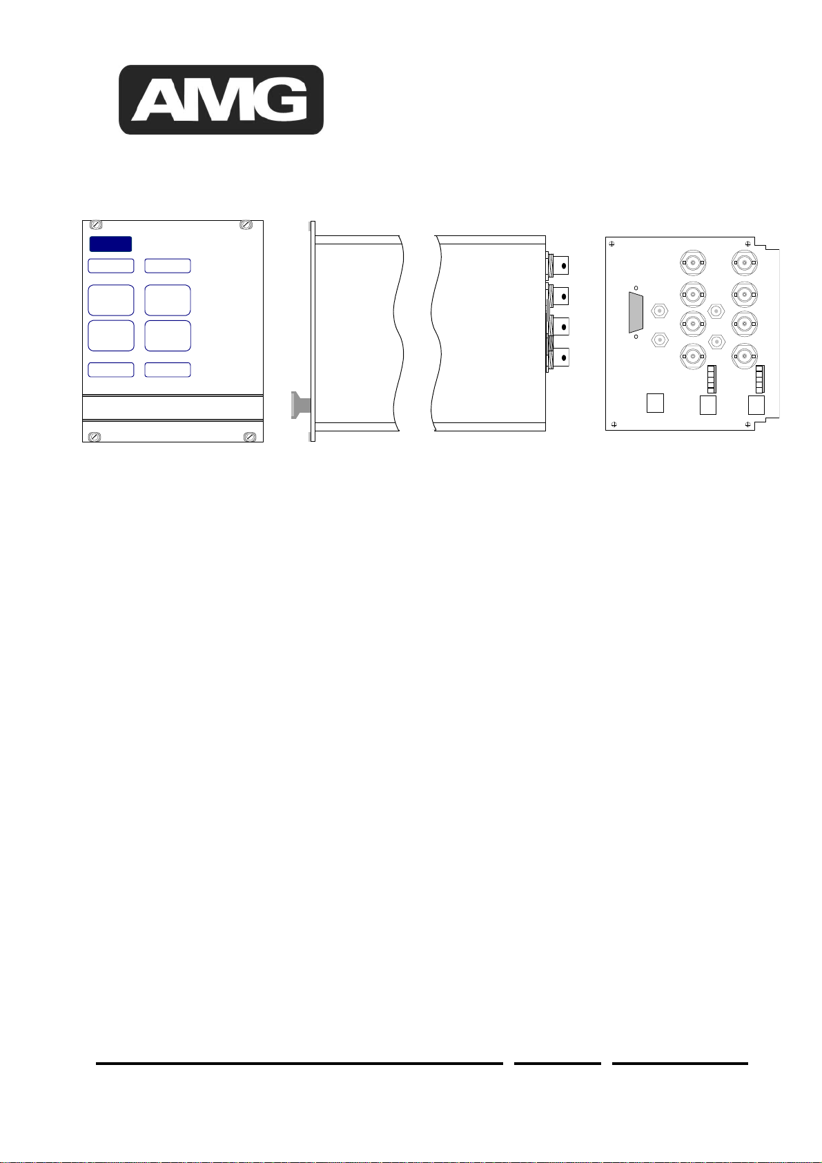
Physical Information
Dimensions
Height ..................................................3U Plug-in
Width....................................................21HP
Depth ...................................................170mm excluding connectors
Weight..................................................1100grams