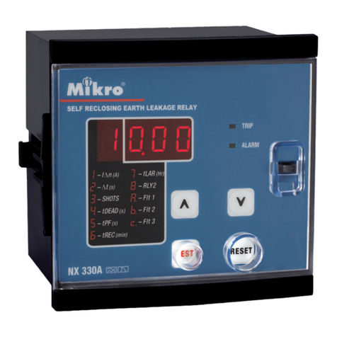
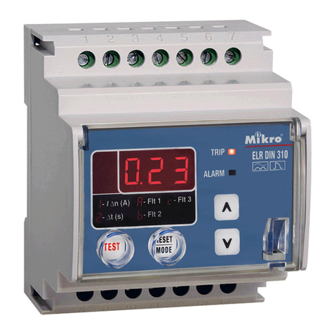
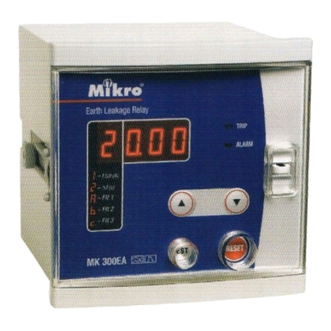
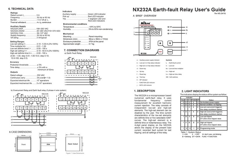
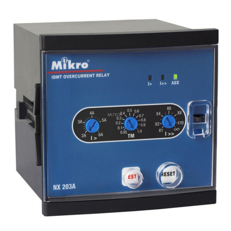
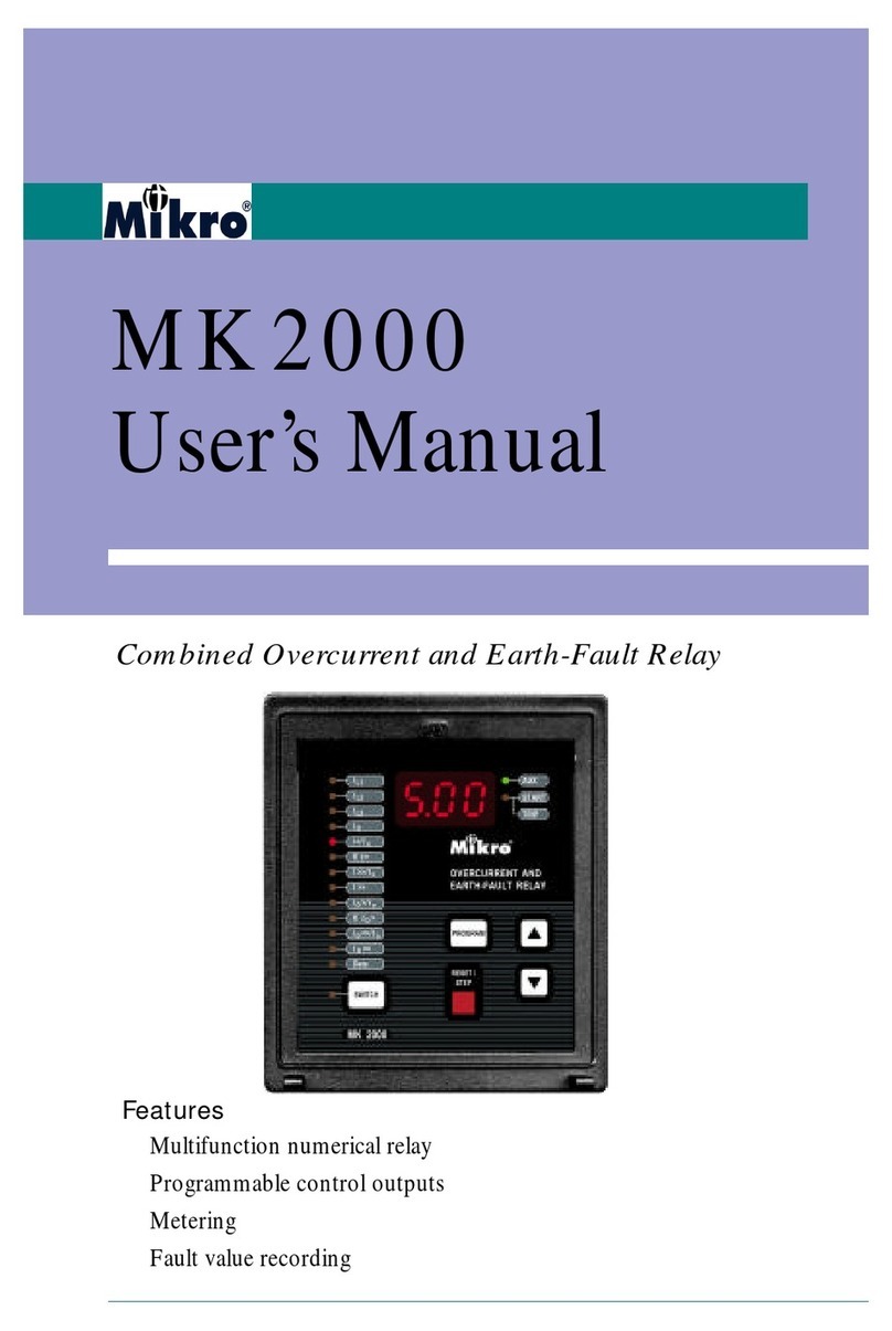
Mikro MK 3000L User manual

MK 3000L
V1.1
Combined Overcurrent and Earth Fault Relay
3 stages phase overcurrent and earth fault
IDMT and definite time
Thermal overload protection
Fault, alarm and event records with timestamp
Disturbance records
CB Maintenance
Multi-shot autoreclose
Trip circuit supervision
RS232 and RS485 MODBUS-RTU communication
Negative sequence overcurrent
Circuit breaker open/close control
Programmable LED
Inrush blocking

2
Table of Contents
1.0 Introduction...........................................................................................................3
1.1 Symbols and Definitions............................................................................................................3
1.2 Main Functions ..........................................................................................................................4
2.0 Front Panel.............................................................................................................5
2.1 LCD Display..............................................................................................................................5
2.2 Keypad.......................................................................................................................................5
2.3 LEDs ..........................................................................................................................................6
2.4 RS232 Port.................................................................................................................................6
2.5 Default Display..........................................................................................................................6
2.6 Alarm Condition.........................................................................................................................6
2.6.1 Alarm Auto Scrolling..............................................................................................................6
3.0 Password.................................................................................................................7
3.1 Password Protection...................................................................................................................7
3.2 Password Entry ..........................................................................................................................7
3.3 Changing Password....................................................................................................................7
4.0 Menus......................................................................................................................7
4.1 Menu Contents...........................................................................................................................7
MEASUREMENTS Menu...............................................................................................................9
RECORDS Menu...........................................................................................................................12
CONFIGURATION Menu.............................................................................................................14
PROTECTION G1 Menu ..............................................................................................................17
PROTECTION G2 Menu ..............................................................................................................22
INPUT Menu..................................................................................................................................22
OUTPUT Menu..............................................................................................................................24
COMMUNICATION Menu...........................................................................................................26
MISC CONTROL Menu................................................................................................................27
5.0 Functions and Descriptions................................................................................31
5.1 Circuit Breaker Failure Protection...........................................................................................31
5.2 Inrush Blocking........................................................................................................................31
5.3 Thermal Overload Protection...................................................................................................32
5.4 Trip Circuit Supervision...........................................................................................................33
5.5 Disturbance Recorder...............................................................................................................35
5.6 Autoreclose ..............................................................................................................................35
5.7 Open CB & Close CB Control.................................................................................................36
5.8 Characteristic Curves...............................................................................................................37
6.0 Case Dimensions..................................................................................................39
7.0 Connection Diagram and Terminal...................................................................39
7.1 Terminal Connection at Rear View..........................................................................................39
7.2 Typical Connection Diagram ...................................................................................................41
8.0 Technical Data......................................................................................................42
9.0 MODBUS Protocol..............................................................................................47
9.1 MODBUS Functions................................................................................................................47
9.2 MODBUS Register..................................................................................................................49
9.3 MODBUS Mapping Format ....................................................................................................57

3
1.0 Introduction
The purpose of this manual is to provide information necessary to install, operate and maintain the
Mikro MK3000L relay.
MK3000L provides protections for 3 independent phase overcurrent elements and one non-
directional earth-fault element. All these elements are connected to the current transformers of the
feeders to be protected. There are 2 sets of current inputs, for 1Aand 5A rated CTs.
The relay comes with liquid crystal display (LCD) with 2 x 16 back-lit alphanumerical characters
and 7 LEDs in which 4 of the LEDs are programmable. An 8 button keypad can be used to access
all measurements, alarm or trip records and settings. Dedicate Open CB (circuit breaker) and Close
CB button is used to manually open and close CB.
There is a RS232 port available on the front panel and a RS485 port on the rear terminals. Using
MODBUS RTU protocol, all stored information including alarm, trip and disturbance records can
be read and settings can be modified with a PC loaded with setting software.
MK3000L has 4 configurable output relays. They can be activated by any of the protection
functions available in the relay. There is also 1 output relay for internal fault indication. There are 2
configurable logic inputs for various functions.
1.1 Symbols and Definitions
In this manual and on the relay, unless the context otherwise requires, the following symbols and
abbreviations shall apply throughout:-
AC : Alternating current
Ack : Acknowledge
Alrm : Alarm
Aux : Auxiliary
CT : Current transformer
CB : Circuit breaker
CBFP : Circuit Breaker Failure Protection
Chg : Change
CLPU : Cold Load Pickup
DC : Direct current
Dmd : Demand
Dmnd : Demand
DMT : Definite time
EF : Earth fault
E/Gnd : Earth/Ground
Genrl : General
IDMT : Inverse definite minimum time
IL1 : Phase 1 current
IL2 : Phase 2 current
IL3 : Phase 3 current
I> : Phase overcurrent first threshold
I>> : Phase overcurrent second threshold
I>>> : Phase overcurrent third threshold
Io/IN : Earth (fault) current
Io> : Earth fault first threshold
Io>> : Earth fault second threshold
Io>>> : Earth fault third threshold
I2> : Negative sequence overcurrent first
threshold
I2>> : Negative sequence overcurrent second
threshold
Invrse : Inverse
Ip : Input
IRF : Internal Relay Failure
LED : Light emitting diodes
Lockd : Locked
OC : Overcurrent
OL : Overloaded
PU : Pickup
RCRD : Record
Reclsr : Recloser
Rmote : Remote
Rst : Reset
Strt : Start
TCS : Trip circuit supervision
Thml : Thermal
tI> : Phase overcurrent first threshold trip
tI>> : Phase overcurrent second threshold trip
tI>>> : Phase overcurrent third threshold trip
tIo> : Earth fault first threshold trip
tIo>> : Earth fault second threshold trip
tIo>>> : Earth fault third threshold trip
tI2> : Negative sequence overcurrent first
threshold trip
tI2>> : Negative sequence overcurrent
second threshold trip

1.2 Main Functions
The following table shows the functions available for MK3000L
ANSI codes Features
50P/51P Three-phase overcurrent
50N/51N Earth fault overcurrent
49RMS Thermal overload (True RMS)
46N Negative sequence overcurrent
Cold load pickup
Instantaneous/start contact
86 Latching output contacts
Setting groups
50BF Circuit breaker failure detection
74TC Trip circuit supervision
94/69 Circuit breaker monitoring and control
68 Blocking logic
Inrush blocking
Auxiliary timers
79 Multi-shot autoreclose
Test of output relays (maintenance)
CB control local/remote
General Features
Number of digital inputs 2
Number of outputs relays 5
Events recording 250
Fault recording 50
Alarms 30
Disturbance recording 6*
Setting group 2
Auxiliary timers 2
Communication ports Front RS232, Rear RS485
Communication Modbus RTU
Time synchronization Via communication port, via digital input
Measurements Currents values & frequency, max and average currents values
* Disturbance recording options: 6 x 3s, 4 x 4s, 3 x 5s, 2 x 7s, 1 x 9s

5
2.0 Front Panel
Using the front panel, the user can easily navigate through the user friendly menu, read
measurements and change settings. The relay status and alarm or trip records are displayed on the
back-lit LCD also.
MK3000L Front panel
2.1 LCD Display
The LCD has 2 lines with 16 characters each. Back light is on when a key is pressed and remain on
for predefined time duration. The brightness can be adjusted to suit the lighting conditions.
2.2 Keypad
There are 8 keys on the front panel.
Up, Down, Enter and Esc are used to navigate through the menus and adjust the settings.
Up : Scroll up the menus or increase setting value.
Down : Scroll down the menus or decrease setting value.
Esc : To exit from menus, submenus or to cancel setting value change. Press and
hold for 1.5 seconds to return to default display from any submenu.
Enter : To enter submenus or to confirm setting value change.
Clear : To reset tripping, reset latched relay. If “CLEAR” Scroll is enabled (under
Configurations-> Display menu) and during no alarm status, it can be
used to scroll through Phase Overcurrent and Earth Fault settings, and to
return to default display from any submenu if pressed and hold for 1.5
seconds.
Record : To display Alarm records. To display successive records, press Record key
again.
LCD Display
Keypad
Front
RS232
Port
Fixed
function
LED
Programmable
LED

6
Open CB : To open circuit breaker from front panel.
Close CB : To close circuit breaker from front panel.
2.3 LEDs
Aux LED : Indicates auxiliary power to the device
Trip LED : Indicates tripping.
Alarm LED : Blinks to indicate non acknowledge alarm (or tripping). Steady on when
the alarm is acknowledged by pressing any key
Programmable LED : 4 Programmable LED can be programmed to turn on when one or more
linked function trigger.
2.4 RS232 Port
The front panel RS232 port has the same MODBUS RTU protocol as the RS485 port on the rear
terminal, though with fixed communication settings: 38400bps, 1 stop bit, even parity, address 1.
All stored information can be read and settings can be modified with a PC loaded with the supplied
setting software.
2.5 Default Display
By default the LCD displays the current value measured for IL1, IL2, IL3 and Io. Input and output
status as well as date and time can be shown by pressing Up key or Down key to change the default
display page. Pressing Esc key always return to current value display.
As soon as an alarm or trip is detected, the display jumps to alarm record display to show the latest
record.
2.6 Alarm Condition
During an alarm or tripping condition, Alarm LED blinks. Alarm record pops up. Any keypress
change the Alarm LED to steady on.
Example of Alarm record title page, showing record 1 out of total 2
records. Press Enter to enter sub page for this record. Press
Record/Down to show next alarm. Press Up to show previous alarm.
Press Esc to return to Default Display. Press Clear to clear the alarm.
If the condition still persists, the alarm cannot be cleared.
Alarm record sub page, showing record date and time. Press
Esc/Enter/RECORD to return to Alarm Record title page.
Clearing all record menu is shown when Up is pressed during display
of Record 1's title page, or RECORD/Down is pressed during display
of Last records title page. Press Clear to clear all Alarm record or Esc
to cancel.
2.6.1 Alarm Auto Scrolling
10 seconds after alarm record pops up, the Alarm display will be auto scrolled to show sub page and
tI> trip 1/2
L2 500A
Date: 03/02/2015
Time: 08:23:44am
Clear all alarm?
Clear=CLEAR

7
subsequently next records until all the records are shown and repeats. Each page is shown for 5
seconds. Example when there are 2 alarm records:
Record 1 Title Page Record 1 Sub Page Record 2 Title Page Record 2 Sub Page Record
1 Title Page ….
Any key pressed stops auto scrolling. After 2 minutes of no activity, with which display still
showing the alarm record, auto scrolling starts again.
3.0 Password
3.1 Password Protection
Relay settings can be view anytime but locked from being changed. A password is required for
changing setting and CB Open, CB Close button pressed.
The password consists of four digit numbers. The factory default password is set as 0000.
The programming mode is indicated with the letter "P" on the right hand side of the display. The
letter "P" remains present as long as the password is active. (2 minutes if there is no key action).
3.2 Password Entry
The input of the password is requested as soon as a modification of a parameter is made or
Open/Close CB button is pressed. The user enters each one of the 4 digits by using up or down key
and validates each digit with Enter. If Esc is pressed in between, the password entering is
terminated.
“Password OK” is shown if correct password is entered. “Password ERROR” is shown if wrong
password is entered.
The display returns to the point of the preceding menu. Pressed Enter again to modify the setting.
If no key is pressed after 2 minutes, the settings are locked. A new password
request is associated with any subsequent setting change.
3.3 Changing Password
To change the password, go to Op Parameter -> Password menu. Enter current password to unlock,
after that the display shows current password. Press Enter again to enter the new password.
4.0 Menus
The menu is divided into 9 main menus and their corresponding submenus. To enter Main menu,
press Enter during default display.
The menu can be navigated by pressing Up, Down, Enter and Esc keys. There is no need of a
password when reading settings and measured values.
4.1 Menu Contents
The Main menu consists of 9 items. The menu structure is shown below:

8
LED x Ena le?
I>?
tI>?
I>>?
tI>>?
I>>>?
tI>>>?
Io>?
tIo>?
Io>>?
tIo>>?
Io>>>?
tIo>>>?
MainDisplay
Page 1
Main Display and Menu Contents
IL1:0.00 IL2:0.00
IL3:0.00 I0 :0.00
Page 2
Output 1 2 3 4
0 0 0 0
Page 3
Input 1 2
0 0
Page 4
Date XX/XX/XXXX
Time XX:XX:XX
1.MEASUREMENTS
IL1
IL2
IL3
Io
I2
Thermal θ
Frequency
IL1 Max
IL2 Max
2.RECORDS
2.1 Fault Rcrds 2.2 Event Rcrds 2.3 Distur Rcrd
Records Num er
Pre-Time
Distur Rec Trig
3.CONFIGURATION
3.1 Op Parameter 3.2 CT Ratio 3.3 Date & Time
Date
Date Format
Time
Time Format
Password
Description
Firmware
Frequency
Active Group
Serial Num er
Phase CT Pri
Phase CT Sec, In
Earth CT Pri
Earth CT Sec, Ion
3.4 Group Select
Chg Group y..
Setting Group
3.5 Display
LCD On Time
Lcd Brightness
"CLEAR" Scroll?
3.6 LED
3.6.1-3.6.4 LED 1-4
tI2>?
tI2>>?
Input 1?
Input 2?
Aux 1?
Aux 2?
Thml Alrm?
Thml Trip?
CB Fail?
Reclsr Run?
Reclsr Lockd?
Io Max
IL1 Avg
IL2 Avg
IL3 Avg
Io Avg
Max & Avg I RST
Time Window

9
Input Func
Input Type
(Func is Aux 1/2)
Aux Timer
4.PROTECTION G1
4.1 Phase OC
I>?
I>
I> Delay Type
I> IDMT Curve
ktI>
tI>
I>>?
I>>
tI>>
I>>>?
I>>> Sample
I>>>
tI>>>
4.2 Earch Fault
Io>?
Io>
Io> Delay Type
Io> IDMT Curve
ktIo>
tIo>
Io>>?
Io>>
tIo>>
Io>>>?
Io>>> Sample
Io>>>
tIo>>>
4.3 Neg Seq OC
I2>?
I2>
I2> Delay Type
I2> IDMT Curve
ktI2>
tI2>
I2>>?
I2>>
tI2>>
4.4 Thermal OL
Thermal OL?
Iθ>
Tθ
k
θ Trip
θ Alarm
5.PROTECTION G2
Similar to
PROTECTION G1
4.5 Autoreclose
Autoreclose?
Dead Time tD1
Dead Time tD2
Dead Time tD3
Dead Time tD4
Reclaim Time tR
Inhi it Time tI
Phase Cycles
Earth Cycles
CYCLES 1 2 3 4
tI>
tI>>
tI>>>
tIo>
tIo>>
tIo>>>
tAux 1
6.INPUT
6.1-6.2 Input 1-2
(Func is Reset)
Rst Trip/Alarm
Rst Thermal θ%
(Func is Blocking)
Block I>?
Block I>>?
Block I>>>?
Block Io>?
Block Io>>?
Block Io>>>?
Block Thml OL?
Block I2>?
Block I2>>?
(Func is TCS)
TCS Delay

10
Relay 2-4 Func
Reset
(Func is Trip)
tI>?
tI>>?
tI>>>?
tIo>?
tIo>>?
tIo>>>?
Thml OL?
tAux 1?
tAux 2?
Remote
tI2>?
tI2>>?
7.OUTPUT
7.1 Relay 1
(Func is Start/Other)
I>?
I>>?
I>>>?
Io>?
Io>>?
Io>>>?
Thml OL(Alarm)?
Aux 1(Alarm)?
Aux 2(Alarm)?
TCS(Alarm)?
Demand(Alarm)?
I2>?
I2>>?
CB Close?
CB Fail?
Reclsr Run?
Reclsr Locked?
CB Alarm?
(Func is CBFP)
Delay
Include Aux?
Relay 1 Func (Trip only)
Reset
tI>?
tI>>?
tI>>>?
tIo>?
tIo>>?
tIo>>>?
Thml OL?
tAux 1?
tAux 2?
Remote
tI2>?
tI2>>?
7.2-7.4 Relay 2-4 7.5 Maint Mode
9.MISC CONTROL
9.1 CB Monitor
CB Opening Time
CB Closing Time
CB Operations
ΣAmps(n) IL1
ΣAmps(n) IL2
ΣAmps(n) IL3
Reset All Value
9.2 CB Alarm
CB Opening Time?
CB Opening Time
CB Closing Time?
CB Closing Time
CB Operations?
CB Operations
ΣAmps(n)?
ΣAmps(n)
n
8.COMMUNICATION
Communication?
Remote Set?
Baud Rate
Parity
Stop Bit
Relay Address
9.3 Inr Blocking
Inr Blocking?
Inr H2 Ratio
Inr tReset
Inr Blocking I>?
Inr Blocking I>>?
Inr Blocking I>>>?
Inr Blocking Io>?
Inr Blocking Io>>?
Inr Blocking Io>>>?
Inr Blocking I2>?
Inr Blocking I2>>?
CLPU Level
CLPU tCL
CLPU I>?
CLPU I>>?
CLPU I>>>?
CLPU Io>?
CLPU Io>>?
CLPU Io>>>?
CLPU Thml OL?
CLPU I2>?
CLPU I2>>?
9.4 Cold Load PU 9.5 Demand Alarm
Demand Alarm?
Idemand>
tIdemand>

11
MEASUREMENTS Menu
Various measurement values can be read under MEASUREMENTS menu. (The values are shown
for illustrative purpose).
Heading of MEASUREMENTS menu. Press Enter to enter submenu
content.
Displays phase 1 current value. Taking into account of Phase CT Pri
ratio.
Displays phase 2 current value. Taking into account of Phase CT Pri
ratio.
Displays phase 3 current value. Taking into account of Phase CT Pri
ratio.
Displays earth current value. Taking into account of E/Gnd CT Pri
ratio.
Displays negative sequence value. Taking into account of Phase CT Pri
ratio.
Displays thermal % state. Calculated on true RMS current values.
Press Clear to clear the % values.
Displays current frequency calculated from phase 1 currents.
Displays peak phase 1 current value.
Displays peak phase 2 current value.
Displays peak phase 3 current value.
Displays peak earth current value.
IL1
52.0A
IL2
88.2A
IL3
64.2A
Io
4.23A
Thermal θ
RST=CLEAR
Frequency
50.01Hz
IL1 Max
120A
IL2 Max
234A
IL3 Max
1.23kA
Io Max
1.23kA
1.MEASUREMENTS
I2
4.23A

12
Displays average phase 1 current value.
Displays average phase 2 current value.
Displays average phase 3 current value.
Displays average earth current value.
To clear the maximum and average values of the currents. Press Clear
to clear these values.
Set the value for the time window (rolling) during which maximum
and average values are stored. Press Enter to change the value.
RECORDS Menu
Heading of RECORDS menu. Press Enter to enter submenu content.
Fault Records Menu
Heading of Fault Record submenu. Press Enter to enter submenu
content.
Example of Fault Record title page, showing trip element, source,
value and record number 1. Press Up or Down to show another record
of Enter to enter sub page for this record. Press Clear to clear this
record.
Fault record sub page 1, showing record date and time. Press down to
show next sub page. Press Esc/Enter to return to Fault Record title
page.
Fault record sub page 2, showing active protection setting group
during fault. Press Up/down to change sub page. Press Esc/Enter to
return to Fault Record title page.
IL1 Avg
323A
IL2 Avg
80.4A
IL3 Avg
78.2A
Io Avg
6.24A
Max & Avg I RST
RST=CLEAR
Time Window
10min
2.RECORDS
2.1 Fault Rcrds
tI> trip [1]
L3 15.2A
Date: 03/01/2016
Time: 10:19:52am
Active Set Group
1

13
Fault record sub page 3, showing L1 current during fault. Press
Up/down to change sub page. Press Esc/Enter to return to Fault
Record title page.
Fault record sub page 4, showing L2 current during fault. Press
Up/down to change sub page. Press Esc/Enter to return to Fault
Record title page.
Fault record sub page 5, showing L3 current during fault. Press
Up/down to change sub page. Press Esc/Enter to return to Fault
Record title page.
Fault record sub page 6, showing Lo current during fault. Press Up to
previous sub page. Press Esc/Enter to return to Fault Record title page.
Event Records Menu
Heading of Event Record submenu. Press Enter to enter submenu
content.
Example of Event title page. Press Enter to enter sub page for this
record.
Event record sub page, showing record date and time. Press Esc/Enter
to return to Fault Record title page.
Disturbance Records Menu
Heading of Disturbance Record submenu. Press Enter to enter
submenu content.
Set the disturbance record length and number. Press Enter to change
between None (disable), 6 Rec x 3 sec, 4 Rec x 4 sec, 3 Rec x 5 sec, 2
Rec x 7 sec and 1 Rec x 9 sec.
Note: Changing the record length and number will cause existing records being
deleted. If necessary, read all wanted records before making changes.
Set the disturbance record pre-time. Step 0.1s.
Criteria which will start the disturbance record function. Setting
choices are ON INST (starts recording on start/instantaneous
thresholds) or ON TRIP (starts recording on a tripping).
IL1 Magnitude
4.86A
IL2 Magnitude
4.52A
IL3 Magnitude
15.2A
Io Magnitude
1.2A
2.2 Event Rcrds
Genrl strt [1]
Date: 03/02/2011
Time: 08:23:44am
2.3 Distur Rcrd
Records Num er
6 Rec x 3 sec
Pre-Time
0.1s
Distur Rec Trig
ON INST
!
!!
!

14
CONFIGURATION Menu
Heading of CONFIGURATION menu. Press Enter to enter submenu
content.
Op parameter Menu
Heading of Op Parameter submenu. Press Enter to enter submenu
content.
This password is required when changing relay settings. Press Enter to
enter a new password. The user needs to enter existing password to
unlock, after that the display shows current password. Press Enter
again to enter the new password.
Model name of this relay
Version of the firmware.
Set the nominal value of the line frequency. Press Enter to change this
value.
Currently active protection group.
CT Ratio Menu
Heading of CT Ratio menu. Press Enter to enter submenu content
Set the rated primary current of the Phase/Line CT.
Set the rated secondary current of the Phase CT according to the CT
input terminal used. This setting affects disturbance record current
scaling only.
Set the rated primary current of the Earth/Ground CT.
Set the rated secondary current of the Earth/Ground Phase CT
according to the CT input terminal used. This setting affects
3.CONFIGURATION
3.1 Op Parameter
Password
****
Description
MK3000L
Firmware
1.0
Frequency
50Hz
3.2 CT Ratio
Phase CT Pri
500A
Earth CT Pri
200A
Active Group
50Hz
Phase CT Sec, In
5A
Earth CT Sec, Ion
1A

15
disturbance record current scaling only.
Note: The CT secondary should be connected to 5A or 1A CT input terminal according to the CT
secondary current rating. The display current is calculated by the formula:
Current at CT input terminal / CT input terminal type x CT Pri (setting above)
For example:
Current at CT input terminal = 3A,
CT input terminal type = 5A,
CT Pri = 200A,
The display value = 3/5 x 200 = 120A
Current at CT input terminal = 3A,
CT input terminal type = 1A,
CT Pri = 100A,
The display value = 3/1 x 100 = 300A
Date & Time Menu
Heading of Date & Time menu. Press Enter to enter submenu content.
Displays the date. Press Enter to change the date.
Set the date format for display. Press Enter to change between
DD/MM/YYYY, MM/DD/YYYY.
Displays the time. Press Enter to change the time, starts from hour,
minute and am/pm (if 12 hour format is selected). Second will be reset
to 0 when enter is pressed for any of the digit.
Set the time format. Press enter to change between 12 and 24 hour.
Group Select Menu
Heading of Group Select menu. Press Enter to enter submenu content.
Set whether the protection group setting is change by Menu or Input.
One of the input function must be set to 'Select Group' if Input is
selected. Press Enter to change.
If above is set to Menu, this will set the active protection group. Press
Enter to change.
3.3 Date & Time
Date
18/01/2016
Date Format
DD/MM/YYYY
Time
10:46:23am
Time Format
12-hour
3.4 Group Select
Chg Group y...
Menu
Setting Group
1

16
Display Menu
Heading of Display menu. Press Enter to enter submenu content.
Set how long the LCD backlight remains on after no key is pressed.
Press Enter to change.
Set the brightness of the LCD backlight. Press Enter to change.
Set if Clear key can be used (during no alarm or trip state) to scroll
through the default display pages, Phase OC and Earth OC settings
(for currently selected group), as well as to return to Default Display
from Record display. This is useful when Up, Down, Enter and Esc
key is inaccessible due to the front panel is covered and locked.
LED Menu
LED4 to LED 7 configuration is used to assign a protection function to a LED output. The LED
lights up when the protection function is active. For tI>, tI>>, tI>>>, tIo>, tIo>>, tIo>>>, tI2> and
tI2>> trip, the LED is latched by its respective alarm record, LED is off when its alarm record is
cleared.
Heading of LED Menu. Press Enter to enter submenu content
LED 4 to LED 7 menu has similar content. The LED 4 menu content is shown below:
Heading of LED 4 Menu. Press Enter to enter submenu content.
Enable or disable LED 4 operation.
If yes is selected, the following menu is shown:
I>? Yes Assigned I> start to LED
tI>? Yes Assigned tI> trip to LED
I>>? Yes Assigned I>> start to LED
tI>>? Yes Assigned tI>> trip to LED
I>>>? Yes Assigned I>>> start to LED
tI>>>? Yes Assigned tI>>> trip to LED
Io>? Yes Assigned Io> start to LED
tIo>? Yes Assigned tIo> trip to LED
3.5 Display
LCD On Time
10min
LCD Brightness
Medium
“CLEAR” Scroll?
No
3.6 LED
3.6.1 LED 4
LED 4 Ena le?
Yes

17
Io>>? Yes Assigned Io>> start to LED
tIo>>? Yes Assigned tIo>> trip to LED
Io>>>? Yes Assigned Io>>> start to LED
tIo>>>? Yes Assigned tIo>>> trip to LED
tI2>? Yes Assigned I2> start to LED
tI2>>? Yes Assigned tI2> trip to LED
Input 1? Yes Assigned Input 1 status to LED
Input 2? Yes Assigned Input 2 status to LED
Aux 1? Yes Assigned Aux1 Alarm/trip to LED
Aux 2? Yes Assigned Aux2 Alarm/trip to LED
Thml Alrm? Yes Assigned thermal alarm to LED
Thml Trip? Yes Assigned thermal trip to LED
CB Fail? Yes Assigned CB fail to LED
Reclsr Run? Yes Assigned recloser running to LED
Reclsr Lockd? Yes Assigned recloser locked to LED
TCS Alrm? Yes Assigned TCS alarm to LED
PROTECTION G1 Menu
Heading of PROTECTION G1 (Group 1) menu. Press Enter to enter
submenu content.
Phase OC Menu
Heading of Phase OC (Overcurrent) menu. Press Enter to enter
submenu content.
I> menu
Set to Yes to enable phase overcurrent first threshold (I>). Then the
following menu is displayed.
Set the value for the current threshold I>.
NOTE : When delay type is IDMT, the maximum setting
recommended should be 2.00In.
Set the time delay type of I>. Setting choices are: IDMT (inverse
definite time curve) and Definite Time.
4.PROTECTION G1
4.1 Phase OC
I>?
Yes
I>
2.00In
I> Delay Type
IDMT

18
If Definite Time is selected, the following menu is displayed:
Set the value for the time delay of I> definite time.
If IDMT is selected, the following menu is displayed:
Set the type of curve.
Set the time multiplier setting value for the curve.
I>> menu
Set to Yes to enable phase overcurrent second threshold (I>>). Then
the following menu is displayed.
Set the value for the current threshold I>>.
Set the value for the time delay of I>> definite time.
I>>> menu
Set to Yes to enable phase overcurrent third threshold (I>>>). Then the
following menu is displayed.
Set to yes to enable I>>> operated on current sample base. Otherwise
it operates on fundamental value. Sample base method will ensure fast
tripping on highly saturated current signal.
Set the value for the current threshold I>>>.
Set the value for the time delay of I>>> definite time.
Earth Fault Menu
Heading of Earth Fault menu. Press Enter to enter submenu content.
tI>
1.00s
I> IDMT Curve
Normal Invrse
ktI>
0.20
I>>?
Yes
I>>
9.00In
tI>>
100ms
I>>>?
Yes
I>>> Sample
Yes
I>>>
20.0In
tI>>>
30ms
4.2 Earth Fault

19
Io> menu
Set to Yes to enable earth fault first threshold (Io>). Then the
following menu is displayed.
Set the value for the current threshold Io>.
NOTE : When delay type is IDMT, the maximum setting
recommended should be 0.5Ion..
Set the time delay type of Io>. Setting choices are: IDMT and Definite
Time.
If Definite Time is selected, the following menu is displayed:
Set the value for the time delay of Io> definite time.
If IDMT is selected, the following menu is displayed:
Set the type of curve.
Set the time multiplier setting value for the curve.
Io>> menu
Set to Yes to earth fault second threshold (Io>>). Then the following
menu is displayed.
Set the value for the current threshold Io>>.
Set the value for the time delay of Io>> definite time.
Io>>> menu
Set to Yes to enable earth fault third threshold (Io>>>). Then the
following menu is displayed.
Set to yes to enable Io>>> operated on current sample base. Otherwise
it operates on fundamental value. Sample base method will ensure fast
tripping on highly saturated current signal.
Io>?
Yes
Io>
0.10Ion
Io> Delay Type
IDMT
tIo>
1.00s
Io> IDMT Curve
Normal Invrse
ktIo>
0.20
Io>>?
Yes
Io>>
1.00Ion
tIo>>
100ms
Io>>>?
Yes
Io>>> Sample
Yes

20
Set the value for the current threshold Io>>>.
Set the value for the time delay of Io>>> definite time.
Neg Seq OC
Heading of Neg Seq OC (Negative Sequence Overcurrent) menu.
Press Enter to enter submenu content.
I2> menu
Set to Yes to enable negative overcurrent first threshold (I2>). Then
the following menu is displayed.
Set the value for the current threshold I2>.
NOTE : When delay type is IDMT, the maximum setting
recommended should be 0.5Ion..
Set the time delay type of I2>. Setting choices are: IDMT and Definite
Time.
If Definite Time is selected, the following menu is displayed:
Set the value for the time delay of I2> definite time.
If IDMT is selected, the following menu is displayed:
Set the type of curve.
Set the time multiplier setting value for the curve.
I2>> menu
Set to Yes to earth fault second threshold (I2>>). Then the following
menu is displayed.
Set the value for the current threshold I2>>.
Io>>>
20.0Ion
tIo>>>
30ms
4.3 Neg Seq OC
I2>?
Yes
I2>
0.10In
I2> Delay Type
IDMT
tI2>
1.00s
I2> IDMT Curve
Normal Invrse
ktI2>
0.20
I2>>?
Yes
I2>>
1.00In
Table of contents
Other Mikro Relay manuals
Popular Relay manuals by other brands
ABB
ABB Relion 620 Series Operation manual
Siemens
Siemens 5TT3 424 operating instructions
Guard master
Guard master Minotaur MSR7R manual

Mitsubishi Electric
Mitsubishi Electric MELPRO-A Series instruction manual
Muuntosahko
Muuntosahko Superintend Trafox VR-16 Short Operating Manual
Notifier
Notifier N-ANN-RLY product manual
Siemens
Siemens SIRIUS 3RF23 0 Series Original operating instructions

Velleman
Velleman VMA332 user manual
Schweitzer Engineering Laboratories
Schweitzer Engineering Laboratories SEL-787-2 manual

ABB
ABB CM Series Operating and installation instructions
SSP
SSP T2 Series operating manual
GE
GE T35 instruction manual
