INSTALLAZIONE
L’installazione deve essere eseguita da personale
tecnico qualificato e deve avvenire in assenza di
tensione. Assicurarsi che lo strumento sia intatto e
non abbia subito danneggiamenti durante il
trasporto. Accertarsi che le tensioni di
alimentazione siano compatibili con i range
consentiti dallo strumento. Attorcigliare tra loro i fili
di collegamento al toroide, tenerli lontano i cavi di
potenza ed in presenza di forti campi
elettromagnetici usare un conduttore schermato.
Ridurre al minimo la distanza tra il toroide ed il relé.
INSTALLATION
Only a qualified technician can do the installation. The
instrument installation must be done in total absence of
voltage. The tool must be intact and it haven’t damages
caused of transport. The power supply must be
compatible with the tool range. Twist together the wires
connecting the relay to the toroid and keep the wires far
from the power cables and use shielded wires if there
are strong magnetics fields. Reduce at the minimum the
length of wires between relay and toroid.
GENERALITA’
Il relé ELR-8MV-TCS in contenitore per montaggio ad
incasso DIN 96x96 ha la possibilità di essere abbinato a
qualsiasi tipo di toroide della serie CT-1.
Due sono i test disponibili: quello manuale (pulsante di
test) e quello automatico del collegamento toroide – relé.
È possibile scegliere se a riposo il relé debba essere
diseccitato (sicurezza negativa) o eccitato (sicurezza
positiva). La sicurezza positiva offre un notevole
vantaggio: in caso di guasto o spegnimento del
differenziale il relé di uscita si apre evitando di lasciare
l’impianto senza protezione.
Il relé è caratterizzato da un campo di taratura sia in
corrente che in tempo molto ampi. La vastità di
regolazione permette di scegliere molto facilmente il
valore d’intervento in modo tale da mantenere i valori
delle tensioni di contatto al disotto dei 50 V come
richiesto dalle norme CEI. Dette regolazioni permettono,
inoltre, di operare una selettività di intervento sia in
corrente che in tempo, quando ci sono più relé posti
sulla linea.
Altra importante caratteristica è l’insensibilità
dell’apparecchio a disturbi esterni in considerazione dei
filtri introdotti sui circuiti di ingresso ed insensibilità alle
correnti continue presenti sulla linea sotto controllo,
secondo quanto richiesto dalle norme VDE.
Il dispositivo é altresi’ in grado anche di effettuare un
controllo sulla funzionalità della bobina e del circuito di
sgancio (funzione TCS).
GENERALITY
The ELR-8MV-TCS which is supplied in a flush mounting DIN
96x96 can be coupled to any type of toroid CT-1’s family.
There are two test available: manual test (test push - button)
and automatic test of torid – relay circuit.
It’s possible to choose if the status of the output relay is
normally excited (NC) or normally not-excited (NO). With the
output relay in a normally excited condition offer a big
advantage: in case of fault or the auxiliary supply cut-off, the
output relay open itself to avoid to leave the installation
without protection.
Its current and time setting range are very wide. This feature
allows to easily choose the tripping current value in the way
that the voltage values are maintained below 50 V, in
compliance with CEI standards. It allow, also, to perform a
tripping selectivity, whenever there are more relay in the
same line.
Another important feature is its insensitivity to external
trouble and pulse current with dc components (present in the
line), due to the filters built on the input circuits, as for the
VDE standards.
The dispositive are able to check the trip circuit of circuit
breakers
1
2
3
4
5
6
7
8
9
17
18
19
20
21
22
14
15
16
11
12
13
ALARM / TRIP
INPUT
TEST
RESET
Reset a distanza
Remote reset
1
2
3
4
CT1/...
UTENZA
LOAD
3
ALIMENTAZIONE
SUPPLY Vc
BA
Vau x:
1-2=110-127Vac
2-3=220-240Vac
1-3=380-415Vac
Vc:
17-18=110-240Vac/dc
17-19=380-415Vac
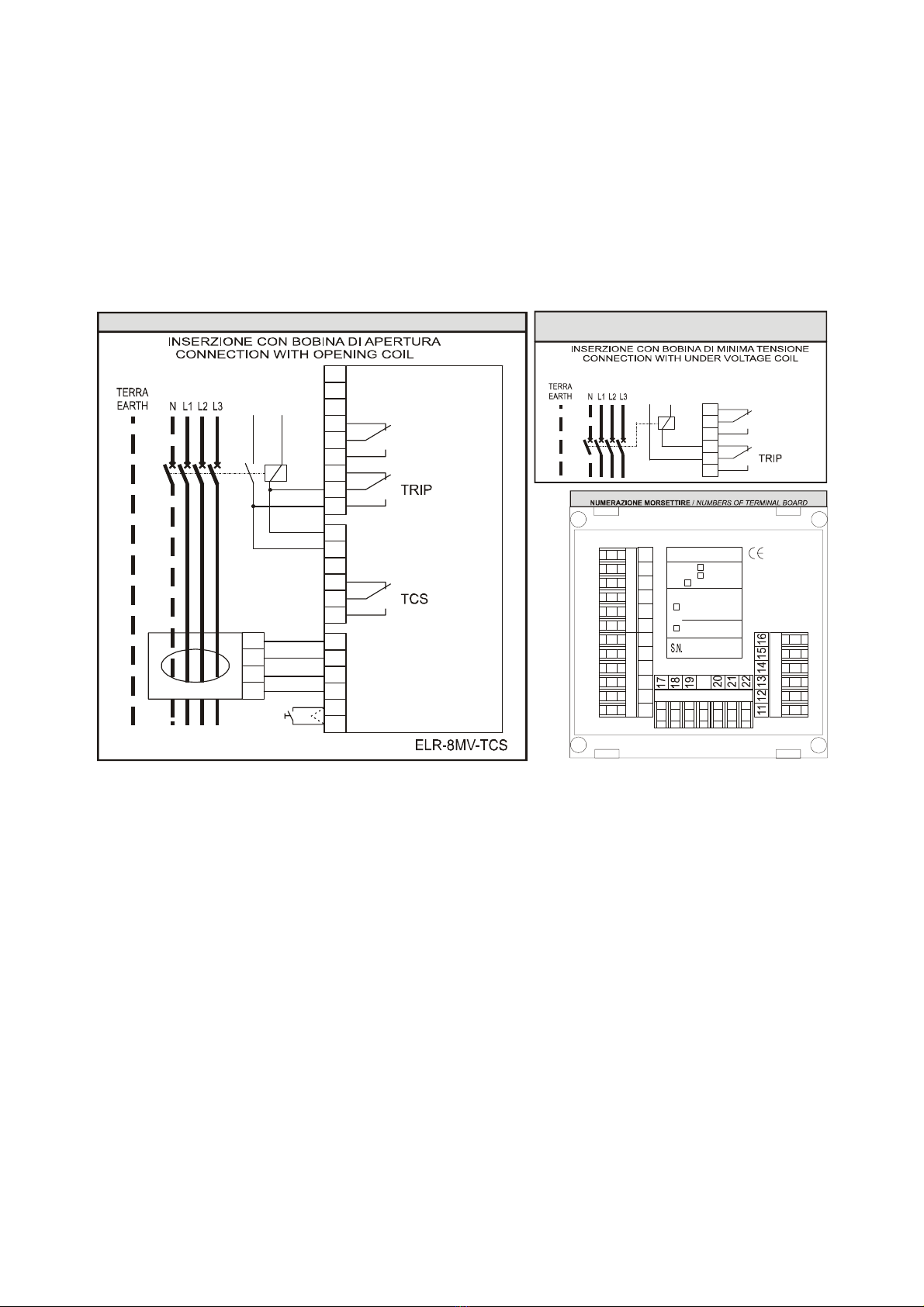
SCHEMA D’INSERZIONE
/ CONNECTING DIAGRAM
4
5
6
7
8
9
ALARM / TRIP
ALIMENTAZIONE
SUPPLY
Vc
Bm
MODIFICHE ALLO SCHEMA D’INSERZIONE
MODIFICATION AT THE CONNECTING DIAGRAM
1 2 3 4 5 6 7 89
Type :
ELR-8MV-TCS
Options: D-display
TCS
M-trip memory
Vau x:
2-3=220-240Vac
1-2=110-127Vac
1-3=380-415Vac
1-2=24Vac/dc
1-3=48Vac/dc
Made in EU
ISTA LATO POSTERIORE
/ BACK SIDE VIEW


