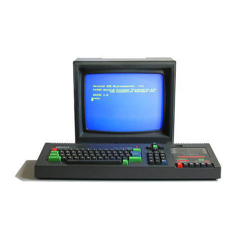
manuals.online logo
Brands
  1. Home
  2. •
  3. Brands
  4. •
  5. AMSTRAD
  6. •
  7. Desktop
  8. •
  9. AMSTRAD CPC464 User manual

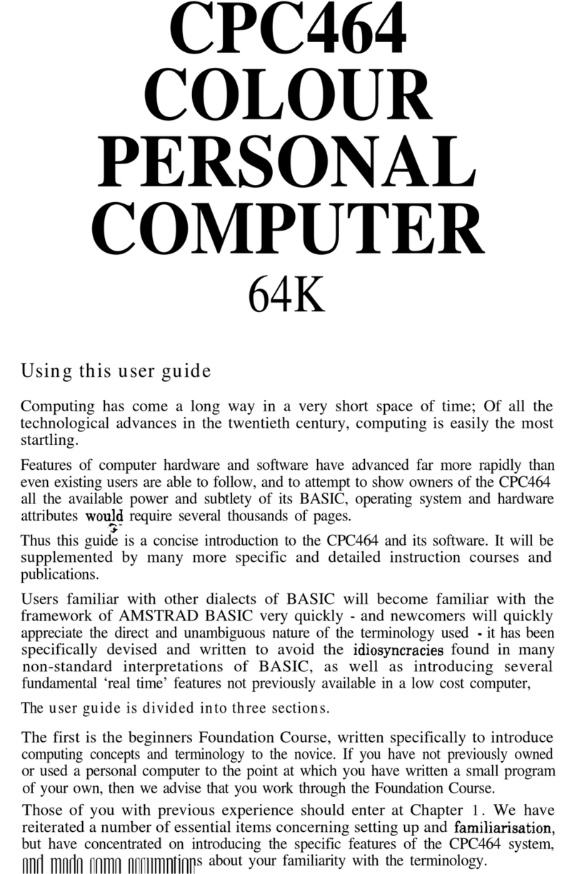
AMSTRAD CPC464 User manual

gee
ees
CONTENTS
Page
Techmcal
Specification
2
Flash
Test
2
CPC464
Cabinet
Parts
List
2
CPC464
Keyboard
Cabinet
Drawing
3
Cassette
Mechanism
and
Parts
List
4,5,6
Cassette
Deck
Alignment
Instructions
6
CPC464
Cassette
PCB
7
CPC464
Cassette
Deck
Circuit
Diagram
8
CPC464
Basic
Hardware
Analysis
Cassette
&
Software
Analysis
10
CPC464
Function
Diagrams
10
&
11
CPC464
Main
PCB
12,13
&
14
CPC464
Circuit
Diagram
15
&16
CPC464
Electrical
Parts
List
17
GT64
Cabinet
Drawing
and
Parts
List
18
GT64
Circuit
Diagram
&
Voltages
19
GT64
Main
PCB
&
Alignment
Instructions
20
GT64
Electrical
Parts
List
21
CTM640
Cabinet
Drawing
&
Parts
List
22
CTM640
Electrical
Parts
List
23
&
24
CTM640
Alignment
Instructions
23
CTM640
Voltages
24
CTM640
Circuit
Diagram
back
pull
out
CTM640
PCB
back
pull
out
SAFETY
TEST
All
monitors
are
safety
tested
to
the
following
specifications.
1).
Flash
Test
Test
at
4kV
between
the
live
and
neutral
of
the
mains
lead
joined
together
and
ALL
accessible
metal
points
on
the
exterior
of
the
set.
2).
Insulation
Resistance
Test
Test
between
the
live
and
neutral
of
the
mains
lead
joined
together
and
ALL
accessible
metal
points
on
the
esterior
of
the
set
to
show
a
resistance
of
at
least
4Mohm.
If
after
servicing
there
is
any
doubt
about
continued
electrical
safety
the
above
tests
should
be
carried
out.
TECHNICAL
SPECIFICATION
LSI
CHIPS:
Z80A
processor
running
at
4MHz
64K
bytes
of
RAM
(over
42K
available
to
user)
32K
bytes
of
ROM
containing
BASIC
and
the
operating
system
6845
CRT
controller
device
Gl
sound
generator
chip
AY-3-8912
3
voice,
7
octave
8255
parallel
1/0
device
interface
to
the
Gl
sound
chip
DISPLAY
SPECIFICATION:
Mode
Normal
High
Res.
Multiclr.
No.
of
4
from
2
from
16
from
Colrs.
27 27
27
Vert.
200
200
200
Dots.
Horiz.
320
640
160
Dots.
Horiz.
40
80
20
Chars.
KEYBOARD:
74
keys
—
qwerty
style,
numeric
cluster,
cursor
and
copy
cursor,
large
enter,
shift,
caps
lock,
tab,
escape,
delete,
clear,
control.
DATACORDER:
Write
speed
software
selectable
—
1K
baud
or
2K
baud,
read
speed
automatically
established
by
software.
Write
protect
interlock.
Motor
on/off
controlled
by
software.
ADD-ON
ABILITY:
Compact
floppy
disk
drive
system
including
CP/M*
and
LOGO
language.
Centronics
compatible
printer.
Joystick(s).
Additional
ROM’s.
Additional
RAM
up
to
8160K.
EXTERNAL
SOCKETS:
PCB
edge
connectors
for
general
purpose
expansion
and
Centronics
parallel
printer.
9
Pin
socket
for
joystick
6
Pin
socket
for
—
RGB
and
sync
—
composite
video
—
luminance
and
sync
3.5mm
socket
for
stereo
sound
output
5mm
socket
for
CPC464
power
supply
(supplied
exclusively
from
screen)
DIMENSIONS
(mm):
w
h
d
Keyboard
:
580
70
=«-170
CTM640
>
375
=
340
365
GT64
>
305
315 335
WEIGHTS
(kg):
Keyboard
t
2.4
CTM640
>
10.6
GT64
:
6.3
POWER
SUPPLY:
Screen
System:
240V
AC
50Hz
(keyboard
and
datacorder
power
supplied
by
screen
system)
*CP/M
is
a
registered
trademark
of
Digital
Research
Inc.
AMSTRAD
and
AMSOFT
are
trademarks
of
Amstrad
Consumer
Electronics
PLC.
In
keeping
with
our
policy
of
continually
improving
our
service,
and
technical
quality
of
our
products,
we
reserve
the
right
to
change
component
types,
manufacturers,
sources
of
supply
or
technical
specification
at
any
time
Keyboard,
Colour
Monitor.
Green
VDU
—
Designed
in
U.K
Made
in
Korea
AMSTRAD
CONSUMER
ELECTRONICS
PLC
BRENTWOOD
HOUSE,
169
KINGS
ROAD,
BRENTWOOD,
ESSEX
CM14
4EF
Telephone:
Brentwood
(0277)
228888
Telex:
995417
AMSELE
G
CPC464
CABINET
PARTS
LIST
Sym|
Description
1
Top
Cabinet
3
Ribs
170001
2
|
On/Off
Switch
170002
3.
|
Vol.
Control
Pot.
170003
4
|
Knob
Vol.
Control
170004
5
|LED
Red
170005
6
|
Cassette
Lid
170006
7
Key
Board
Assy.
170007A
Z.7D101
7
|Key
Board
Assy.
170007B
270102
8
|
Rubber
Contact
mat.
170008
Key
Board
9
|Rubber
Contact
Mat
170009
Digit
10
|
Rubber
Contact
Mat
170010
Spacer
11
Bottom
Cabinet
170011
3
Ribs
12
|Cassette
Mechanism
170012
13
|
Tape
Counter
170013
14
|Counter
Belt
170014
15
|
Record
Button
Cass.
170015
16
|
Play
Button
Cass.
170016
17
|Rewind
Button
Cass.
170017
18
|Fast
Forward
Button
170018
Cass.
Stop/Eject
Button
170019
Cass.
Pause
Button
Cass.
170020
Cass.
Door
Spring
170021
1/0
Socket
170022
User
Port
Socket
170023
D.C.
Socket
170024
DIN
Socket
170025
Inlay
Main
170026
Inlay
Cassette
170027
Keyboard
Contact
170028
P.C.B.
/A
Keyboard
Contact
P.C.B.
/B
Bottom
Cabinet
5
Ribs
Top
Cabinet
5
Ribs
Speaker
170029
170030
170031
170124
CPC464
CABINET
DRAWING
CASSETTE
MECHANISM
CASSETTE
MECHANISM
CPC464
CASSETTE
MECHANISM
PARTS
LIST
Sym
|Description
R/P
Head
Erase
Head
Head
Base
Auto
Stop
Arm
Stopper
809172
Pinch
Roller
Assembly
809162
Spring
Pinch
Roller
809161
Fibre
Washer
809175
Rewind
Spool
809160
Take
Up
Spool
809159
Record
Safety
Lever
809158
Idler
Gear
809173
Back
Up
Spring
170203
Main
Belt
170204
Flywheel
809156
Locking
Plate
Stopper
170205
Locking
Plate
170206
Spring
Post
Locking
Plate
170207
Motor
170208
Idler
Assembly
809155
Pause
Lock
Plate
809168
Leaf
Switch
809157
F.F.
Idler
Arm
Assembly
809152
Eject
Lever
Cassette
Door
170209
Spring
Cassette
Buttons
170210
Motor
Pulley
170211
jLeaf
Switch
170212
170201
170202
809170
809171
CASSETTE
DECK
ALIGNMENT
INSTRUCTIONS
To
check
cassette
module
independently
of
the
C.P.U.
connect
5V
DC
across
points
B(-)
and
C(+),
and
link
E
to
G
and
H
to
F.
The
cassette
will
then
operate
in
an
audio
mode.
(See
page
8
-
Cassette
Circuit
Diagram)
Equipment
Required:
Frequency
Counter,
AV.O.,
V.T.V.M.,
Oscilloscope
&
Test
Tape.
STEP
FUNCTION
SIGNAL
IN
SIGNAL
OUT
METHOD
REMARKS
Cassette
Azimuth
Adjustment.
Monitor
V.T.V.M.
1)
Insert
Test
Tape
recorded
at
6kHz
constant.
Monitor
switched
on
and
fix
2)
Set
Volume
to
maximum
on
CPC464.
connections.
3)
Connect
V.T.V.M.
to
Pin
7
of
I.C.302
to
read
between
330mV
to
520mvV.
By
adjusting
azimuth
screw
on
the
cassette
head.
2.
Speed
Check.
Put
the
standard
tape
|
Monitor
Check
output
from
the
tape
on
the
oscilloscope.
Speed
variation
£4%
will
not
in
the
cassette
Oscilloscope.
The
range
to
be
used
is
100uS.
affect
software
loading.
mechanism.
9b81-
€
/-Id
yS000SW
COE
Id
Yi000LW
l0EGId
9d
ALLASSVO
V9VIdd
(921UM)
a+
(49018)
GND
BLOGS
PE
CH
100d)
Si:
Gee
OFIFYT
10E2/
8SS2-1
[Dd
VSO00LH
(Oesod
64-8-1-d@s
1
4-S>9
i
c
WVYSVIC
LINDYID
WOAG
ALLASSVO
p9vDd9
75000SH
CONNECT
TO
CPC464
-
BASIC
240V
AC
MAINS
HARDVVARE
ANALYSIS
RED
LED
LIGHTS
REPLACE
MAINS
FUSE
CHECK
FOR
FAULTY
CABLE
OR
PLUG
ASSY
%
FROM
MONITOR
2
:
uw
YES
—_
5
i
Coane
a
FAULTY
LED
e
SOLDERED.
BROKEN
PCB
TRACK
z
q0iNze
FAULTY
CONNECTER
CHECK
KEYBOARD
PCB
F
FOR
SIGNS
OF
ABUSE:
fe)
-
CRACKS
a
—
LIQUID
SPILLAGE
a
~
DISTORTED
MOUNTING
5
CHECK
CONNECTOR
LEAD
#
TEST
SWITCH
AND
TERMINATION
5
ON
COMPUTER
FAULTY
SWITCH
KEYBOARD
UNI
RGB
VIDEO
ANY
YES
CONNECTOR
PICTURE
INSERTED
AT
ALL
?
CHECK
KEYBOARD
IF
UNIT
STILL
TRY
REPLACE
OK
FAULTLY
SEEK
TAPE
ANOTHER
SPECIALIST
CONNECTOR
TAPE
ADVICE
NO
IMPROVEMENT
FAULTY
AUDIO
AMP
OR
SPEAKER
FAULTY
VOLUME
CONTROL
FAULTY
AUDIO
CONNECTOR
PLUG
/SOCKET
FAULTY
AY-3-8192
SOUND
IC
SEE
CASSETTE
FLOW
CHART
NO
K
STILL
NOTHING
(
FAULTY
ULA
rc
A
XK
a
FAULTY
VIDEO
CONNECTOR
FAULTY
CABLE
ASSY
FAULTY
ULA
FAULTY
PCB
r
CHECK
FAULTY
MONITOR
CABLE
TERMINATION
INTERNAL
CONNECTORS
%
BRIGHTNESS
CONTROL
Z80A
6845
CRYSTAL
RAM
CASSETTE
&
SOFTWARE
ANALYSIS
CHECK
CLEAN
CHECK
HEAD
CHECK
SWITCH
CHECK
TAPE
CONNECTIONS
ON
CASSETTE
MOTOR
CONT-
TO
TAPE
DECK
TAPE
HEAD
ALIGNMENT
KEYS
ROL
RELAY
POSSIBLE
FAULT
WITH
COMPUTER
BOARD:RAM
FAILURE
ULA
FAILURE
SOFTWARE
LOADS,
BUT
WITH
UNUSUAL
RESULTS
N.B
ACTUAL
‘PHYSICAL’
DAMAGE
TO
Full
diagnostic
teste
on
the
C.P.U.
can
be
carried
out
using
the
SOFTWARE
TAPE
WILL
PREVENT
Amstrad
RP1
Test
Pack.
IT
FROM
LOADING
AT
ALL:
IE
Please
contact
Amstrad
PLC
for
information
on
same.
THERE
WILL
BE
NO
‘HALF’
WORKING
PROGRAMS.
THEY
EITHER
LOAD-
OR
THEY
DON'T.
CPC464
FUNCTION
DIAGRAMS
ENA
-
(Cil4
veo
8Q
6D 7D
72
62
6D
5D 5a
ICH3
Veo
2G
ty!
2A4
1¥2
243
13
242
lYA
2Al
OUTPUTIQ
ID
2D 20
32
3D
4D
42
GND
CONROL
1C104.105
STROBE
A
7
yeroag
vec.
26
SELECT
PATA
INPUTS
_
OUTPUT
ICHO
Yoo
ga
4A
4Y 98
3A
GY
1G
BAA
|
A
lic
ic2
ici
ico
Vy
PEER
iP
OE eT
EARERRCAREARCAGE:
/
BTU
EI
tI
STROBE.
OU
BUT
iG
seLECT
DATA
INPUTS
1Y
~
GND
PAS
IBS
1Ne
OA
eB
2k
“GND
INPUTS
OUTPUTS
AB
C
Dd
9
8
A B
CD
BCD
-TO-DECIMAL
123456789
ICil2
Veco
4B
4A
4Y 3B
GA
OY
iclol
fia)
fe)
fe]
il
1A
1B
OLY)
2A
2B
O2Y
=~
GND
{C106
Vcc
8@
8D
7D
7Q
6@
6D
5D
5@
CLOCK
ICl25
cc
48
4A
4Y¥
3B
3A OY
eet
Eley)
TEV
TT
I
CLEAR
12
ID
2D 2@ 3@ 3D
4D
4
GND
iA
1B fy
2A
2B
2Y
GND
11
FUNCTION
FOR
A
MICROCOMPUTER
AND
IC's
DISPTMG
cuDISP
Vee
ANALOG
CHANNEL
C
TEST
|
Vee
ANALOG
CHANNEL
B
ANALOG
CHANNAL
A
Vss
10A7
10A6
10A5
10A4
1043
10A2
10Ai
I0Ag
(C108
IC102
CPC464
FUNCTION
DIAGRAMS
PAZ
lo
PAe*
PORT
A|
PAi
**
READ
INPUTS
RD
CHIP
xe
SELECT
CS
PORT
ADRESS
INPUTS
Yo
PORTC
pao
~-[4|
GND
[ar
>
Ao
™
PC7
~~
PCé6
pcs
*+([/2}
PC4
13
PCo
+>
|/4
PCy
[5
PC2
**/6
10/07
HO]-+pa4
Au
—PAS|
yp
ADRESS.
|
em
pas
|
PORTA
Aa
B7]=PA7
ik
Aia~-[4]
ITE
WR
CONTROL
Ais
RESET
~
5
INPUTS
p
L4~-Do
(
Dav
oD}.
DATA
D3"*
Bus|
~?
D2
Ds*
=D3|
DATA
De
BASS
Da
+5V-
Ds
De
“D6
DATA
~
bus|
°7
D7
Do
vec
|
Di
PBT
INT
~
cey
|
INT
PBs
CONTROL|
NMI
>
pps
|
Yo
HALT
—
PORT
B
Pnebd
sysrem
|
MREQ
=
=»
PBS
CONTROU
FORQ
~
20,
Y
ee
Y
1
ESC]
Q
|TAB
LOck
i
¢
Va
V
¥
7
pa
ee
Com
Brace
Gomes
e.
Fa
V,
yo
nae
&
é
R
y,
G
F
B
Ke
V7
ce
te
eo
iC
itt
44,
|
ADRESS
As
BUS
RESH
|
system
CONTROL
cPy
CONTROL
bs]
BUSRQ
CPU
BUS
CONTROL
~RD
~+WR
|
sysTEM
CONTROL
ake
Ey=23
STI/0!
Sound
Jack
1103
2
eo
4
tT
rorrrc---
é
HD6845SP
CRTC
Je
23256
256K
Bit
Rom
4
Sound
Generator
2ORAGAS
CONI01
J102
i
!
po-—-t-------—
€66CSECS
HM4864P-2
AY-3-8912
j
vt
fas]
oO
a
a
fee
eS.
~@
=
‘
6:
Oo
po
#
lo
lo
3
}2
|
BIS
E|6
2/8|
|
|
”
g|9/8i5|a
iil
3/2}
0/0)
z
et
rr
8121
Sha
<
.
AlalSlzialo|
|=
we
Li
LjslslEls!,|
2
S|
Sa/a/o)
al’!
2
DSSS
°
is
re)
=
Qo
=
ao
n
|
MOS
IANIOlajay
Nn)
|
BISlslSiNisis
|
O/O]
51
3/C]
5/5)
5
OjOlAIS|O|GIo|G
a
©
ajofolo
lo
OT
ON
|wWlAio
=
Bale
(2
|S
[esis
=
HDD
O|n
ln
lola
je)
je
fe)
s
TSS
|S
SSS
BJM
RIN
IN
TN
IN
$
if
a
a
Le
S
°
es
o
rorm
oO
ited
°
Oo
tlo
Oln
ojo
ie]
‘aseabepean
“i
i
0
“
a
a
;
|
ae
7
Ae
yozog/ice
100d9
aD
0))84
LNdN!I
NO
APY
Td
3}1UM
Ni
GNNOS
uaa
L1NdO
viva
onlg
Ni
virgd
.
3
7
eho
ad
3}IUM
a+
a
“|
LY
@rae
>
o.
°
_o
.
HODIG
pone
;
ped
at
°
LD
©
4
12
SOUND.
CLOCK
RESET
SOUND
OUT
ee
ee
ee
Cr
2g
es
Ee
I
eS
Se
Se
eres,
iS
EEE
eae
re
es:
eae
a
Sa
6
2
_
3456789101
vec
3
p++
2
VIO
Rl
x2
x9
x4
x5
x68
x7
x8 x9
8
>
Be]
ee
g
ee
ep
ee
oe
é
ay
13
”
5
14
6
1107
i.
2
>
‘
sl
3
p
CONNECTOR
HsLbersA.
2
17
-Y3°
|
¢
20
WAY
2.50
IN
LINE)
P.l.0
:
pie
OY
cure
7]
19
Yt
2
sd
28
2
30.
—
3t
>
H
MOTOR
=
gas
SOUND
ree
8
pe
fp
PORT
34
=|
910
>
E
RD
DATA
=
bo
FS
=F
a
>D
WR
DATA
See
Pe
ba
oe
+5V
2.9)
ise
Opp
ao
eee
BD
re
ja;
s{|—
Ce
&
Att
ajc.
190d
bo
a9
Ai
18
Ae
#2
AO
S
TORD
=
1
wR
os
10"
=
DF
6s +s
(
EXPANSION
)
at2
R102
R101
8
Sot
ct10
20K
§
NS
aeieo
Ic110
ai
‘
(rasize
=
p
6
PRaaena
cioee
z
p
RESET
fova?
>|
BS
REET
sono
rat
SOUND
an
Al4
Aa
AI2
Atl
att
Bosra
5
ato
Int
R120
ag
AI
at
Tix
48
READY
©
fo
a?
az
i
AS
Mm
a3
3
1¢—2
ao
22
no
M0
0?
Dé
DS
De
03
pe
DI
Do
LULL!
SOD
AIS
wo
ala
al
at2
Ala
C10S-Ct28
O.1
X
24
EXPANSION
CONNECTOR
eeeeeaaaeee
10
11
12 13
14
15
16 17 18
19
20
21
a?
as a3
Al
07
tS
as
ato
we
AS MM
a2 40
ve
Ds
ws
24
»,
CPC464
CIRCUIT
DIAGRAM
¢
tz
>
|
*
AIS
2
Als
oft
1
I
Ici0g
>9
cCONe
74LS153
S
SPARE
a3
>?
FIRE
1
:
a7
>
FIRE
2
PADDLE
>
4
RIGHT
PORT
>3
LEFT
9 PIN
*D?
2
DOWN
CONNECTOR
en
102
>
8
COMMON
1c110
7481322
pit
1
STR
De
06
Ec
>7
DS
pe
be
|
pare
PS
Dg
pa
te
|
BGs
>3
DI
5
>
2
DO
“——+>s
o
>
11
BUSY
mana
3
GAD
14.16019.20.21.22.23,
24,25.
25227528233
ba
SOMAY
0.1°EDGE
CONN
111!
1
6
wes
Lt
i
2330
31 32
mM
16
cru
:
“445
o
20
1
7
a
1
TA
i
Se
A
RR
a
ae
2
[ee
ee
a
FT
2
2
Ls
|
q
=
8
R139
39
hy)»
(PASSIVE
vec!
12
12
PULL
UP)
|
22]
5
1a
vec
7
c104
194
Mt
Os!
iq.
RD
PUL
LPS
F
dq
Tora
xD
10
KT
re
close
DECOUPLING
wMAtZ
—|
2
:
MATT
cS
aid
MA?
RA
sa
as
RS
vr
WAS
o7
|
28
v7
bs
bee
De
bs
+28
DS
ba
+s
D4
va
+
03
D2
pe
pr
-
22
Dt
33
bo
oo
2
as
RESET
s
Re
L
PEN
10K
13
CURSOR
1110
74LS132
a
8
to
ae
Cl
3
ORD
TOWR
ret
ZB0
DATA
BUS
EXPANSION
BUS
VIDEO
GUTPUT
CONNECTOR
J101
¢
GPIN
DIN)
Value
Carbon
Film
Resistors
(all
“aW
unless
shown
otherwise)
560hm
680hm
1000hm
1200hm
1800hm
2200hm
3300hm
560ohm
6800hm
8200hm
1kohm
2k2ohm
3k3o0hm
4k70hm
5k6o0hm
10kohm
12kohm
18kohm
22kohm
33kohm
47kohm
180kohm
1Mohm
120hm(%2W)
CPC464
ELECTRICAL
PARTS
LIST
Circuit
Reference
R126,
128,
130,
136,
137
R143,
144
R154,
313,
325
R125,
127,
129,
135,
301
R324
R113,
121-123,
132,
145
R102-112,
124
R321
R320,
323
R314
R114-117,
120, 133,
142
309,
312
R318
R308,
311
R101,
118,
119,
304,
305
R319,
322
R302,
303,
307
R317
R316
R138,
139
Electrolytic
Capacitors
10022
10028
10032
10034
10037
10040
10044
10050
10052
10054
10061
10069
10073
10077
10079
10085
10087
10091
10093
10097
10101
10115
10147
170126
150514
400107
400107
170126
24004
24007
24013
24020
170217
170128
170129
1uF/50V
C309,
311,
314
10uF/16V
C324
22uF/10V
C308,
318
47uF/10V.
C101,
102, 303,
306
100uF/10V
C301,
304
100uUF/16V
C315
470uF/10V
C322
|
Ceramic
Capacitors
33pF/50V
C316
200pF/50V
C321
220pF/50V
C310
270pF/50V
C313
470pF/50V
C307
0.001uF/50V_
|
C320
0.022uF/50V
|
C317,
319,
323
0.1uF/25V
C104-128
Polystyrene
Capacitors
0.001uF
C312
0.01uF
C305
0.068uF
C302
|
Circuit
Ref.
|
Description
1.C.s
C101
HD74LS145
1C102
AY-3-8912
1IC103
TMM-23256P-1950
1C104,
105,
HD74LS153
109,
113
IC106
HD74LS273
IC107
M5L8255AP-5
1C108
HK6845SP
16110,
112
HD74LS132
C111
Z8400APS
10114
HD74LS373
IC115
HD74LS244
1C116
20RA043
1C117-124
HM4864U-2
1IC125
ZN7400E-D3
IC304
LA4140
[:ca02
LA6324
Part
No.
170101
40001
170102
170103
170104
170105
170106
170107
40080
170108
170109
40007
170110
40008
170111
170112
Part
No.
Description
Circuit
Ref.
Transistors
Q101
KTC2120Y
170113
Q102,
301
KTC1815Y
170114
Q103
ZTX312L
50001
Diodes
D101
D301
D302
Coils
&
Tx.
L301
82uH
T101
C-12
Jacks
&
Connectors
SIL
-
IN4002
400111
LED
-
Red.
SLP145B
170116
SIL
-
1S2472
-
HL
|
170115
170117
170118
J101
DIN
Socket
6
Pin
170025
J102
Joystick
Socket
9
Pin
170023
J103
Input/Output
Socket
170022
3.5mm
R.C.A.
J104
DC
Jack
Socket
170024
J105-112,
116]
Socket
I.C.
8
Pin
Dual
In
Line
170119
J113
Socket
I.C.
14
Pin
Dualln
Line
|
170120
J114,115
Socket
I.C.
20
Pin
Dual
In
Line
170121
Switches
SW301
SW302
SW303
Miscellaneous
170122
170002
170007
Slide
Switch
R/P
Power
On/Off
Key
Board
Assembly
VR301
Volume
Control
20k
170003
RY301
Relay
17.0123
SP301
Speaker
170124
X101
Crystal
HC-18/u
16MHz
170125
ZLEOLL
pPi0oO
NTG
QLEOZLL
pio9
‘9'0
6LSO/L
‘JOq
ssoujyubug
BSLSOLL
}Og
ysesyUuOD
ZLGOLL
Od
PIOH
‘A
Q9LSOZL
YOUMS
HO/UO
SLSOZL
HO/UO
uO}Ng
VISOLIL
sqouy
[o1]U0D
ELSGOLL
jourqey
se98yY
ZLSOLL/S
JOWIOJSUCI]
JOMOd
LELSOLL
yey00S
"LHD
OLSOLL
BHO,
UO!1D9/1Eq
60SO/1
Mal9g
Bulxi4
80SOZ1
JOYUSEM
[elOW
ZOSOLZL
UddIDH
1Y'O
9OSOLL
(4)
‘@'O'd
JexORIg
SOSOLL
(1)
‘@'0'd
JeNOBIG
vposol|
(7)
yourqey
JeyORIg
COSOLL
(y)
Joulqey
jeyoRlg
cOSOZL
dwe|9
a1qe9
LOSOLL
yeulqeyd
juoly
uoijduoseag
|
wks
TH“NYNTOONM
OD
LSIT
SLYVd
LANIGVD
v9L5D
a3AOWsY
34
ION
1SNWw*e
GIYVW
SLYVd
i
NOILLNVD
1SI1
SLYVd
GNV
DNIMVYEC
LANISVO
P9LD
18
GT64
CIRCUIT
DIAGRAM
Lot
|
-
71011202
WES
MZ/t
MES
MB/I
OlADS)
|
1623
ol
“ia
z
1
a
TERE
Ee
ea
ES
PCB701
GT64
VOLTAGE
DATA
C701
-
UPC1031H2
1-5.99V
DC
2-11.98V
DC
3
-
10.86V
DC
4-10.45V
DC
5
-0.61V
DC
6
-
2.93V
DC
7
-
5.26V
DC
8-
OV
DC
9-6.0V
DC
10-11.99V
DC
1C501
-
L78MG
-
20.1V
DC
-
OV
DC
3-12.5V
DC
4-49V
DC
13.6V
DC
20.6V
DC
5.5V
DC
12.6V
DC
Q501
5.1V
DC
Q502
12.0V
DC
Q605
or
with
an
‘S’
prefix
on
the
part
numbers;
are
safety
critical
items
and
must
be
replaced
with
items
having
an
identical
safety
specification.
All
these
items
may
be
purchased
direct
from
Note:
All
parts
shown
with
either
the
symbol
AN
AMSTRAD
CONSUMER
ELECTRONICS
PLC.
2.2V
DC
39.5V
DC
2.0V
DC
19
1P09051
s
=
a
+
Q
8
‘
oe
Ala
27aeg
iiss:
(HO22"0
SOSH
tae
eset
jo
a
ae
&
=
=
.
asst
&
EL
ible
yinz
149
&
()
ote
GS
Ose
=
'29u
E199
eSu6
Ose
5.
Le
2194
Sno
Ge
a
wi
3
5
Sg
a
Sg
HEF:
0
71_0-——*
SS
Co
a
as
ae
-
ee
is
ea
eS
“org
*
“=
ee
00
Wel
205d
aoe
yosa
&
159
,
2=—
QbE
6194
Sa)
_.
Bees
go:
ee
fe
3
S=So
Seer
836
Ss
S
we
~e
8
SS-
+S
~
ogda
«COS
*KeEg
=
——*
S5~
SS
a
a
See
iS
sae
_ 2
ee
ae
aoe
€0S@
=
©
oe
&
ie
ss
8
SO
eee
eee
Re
=8
Ss
\
Ss
i
eas
eee
4
£922
Oct
Me
USY
ea
|
3
Pe
DOLP
ASI
1
\
22
veLe0Sd
—
0065,
20s
4199
oN
=
Se
SS
SS
—
:
eae?
+[SoqsAsgqs
zro00
1099
Gy
ek
a
al
Sass
Sas
:
‘
=\
=
Mi
OGLE
Siw
ririt
“rae
jos
=
0
BA
3
RY
de
ts
J
do!
60S0
fed
MEE
2ELY
a}8
B48
Rice
Re.
s
Wal?
bog
Gc
8
iS
(MONLY
bI9a
ee
i
¢
Qi
|
real
o00lAol
ies
4
o
2
oe
&
Rsls
5
a
3
N
re)
=
YEZSOLY
one
rs
ce7a
“87
“wae?
ae
2
So
=
z
O¢rg0
co:
Gb
yt
2
315)
EN
Were
ZOLA
L
pros
PeHLDIASE
_
S
Norzoly
=
ELAS
tot”
POLS
Zed!
it
@
“E0LD
ty
ae)
Oe
ee)
a8
Vee
REE
|
Polk
OE
OO
oh
5
233—+@ur00
1012
SMe
4049
500"
SSR
gy
=f
2
ozzf0)
=\=
ss
S
Ag
SEeae
Ss
ss
S
:
=
S
o0L0
aa
2
AEE
|
Bene
DSILY
@e
f
a)
8
NO
LPASI
OCLO
a!
‘
oA
Se
a
ths
L¥
Eel
a3
;
“ye
Orage
Gage
a?
6
vel.
Cho.
—
§
fal
one
OLb
089
TLE
Site
ny,
NS
——_
=
&
&
ae
foul
bile
/
8
‘
8)
8
2
GLP
OcLY
|
os
S4)
=
40}.
a
ES
wort
Fe
ie
As
&
@*
8
re)
3
VS
se
eee
crs
35
Set
phe.
gues
oS
OR
Q
~
=
ln
Ss
S
oS
10L0,4.37
@/0°08ILI
5%
58
=
£E09'0_
ite
ty
re
xeprsa™'zoea
@egooee.o
*F*
(dbes00n00r
=
th
i6
(Gi
ws
eo?
—1
+
on
CLO
cea
cg
!
H
&
zz
Ol
1198
04-68,
/2L4
ySTLILY
6219
SESS
SS
BZ
y
O220
00-4
50s
sea
dere
e
—
one
‘=
oe
e
022A
eo
OT
Me
220%
egvosy
@
Set
GLa
L409
*bILD
o90ASold
pond
os
Se
Be
M103,
XS
~=
5
/
Sa.
a
-:
ste
2
&
ara
88
Ja
Deh
O70,
9s
$
:
ei
sca
=
SN
fae
oe
=
3/40
i
even
=
Qs
ag
fer
oe
GEMCIAR
at
hts
\
in
2
3
=
Mo
aA
Ne
voenl
pola
S
=+4S!
8}
-ora097
/
eee
°
3
‘0
SILINS
&
es
1/091
=
EG?
BO!
PIL
oo}
x]
|S)
S
reLg*
ts
=
8
YHDF
Lad
a
SE
pen
cod
SI
RIL
S|
cag
95%
A
Mee
OISY
|
Nore
SLY
leld
geld
8
Gow
a)
=e
es
20L80d
OL
$3
FUNCTION
SIGNAL
IN
SIGNAL
OUT
METHOD
|
~~~
REMARKS
5V
Adjustment.
Monitor
Switched
on.
AN.O.
across
C519.
Adjust
VR501
to
obtain
SV.
Pane
=|
12V
Adjustment.
Monitor
switched
on.
Emitter
of
Q502
&
Earth.
|
Adjust
VR502
to
obtain
12V.
a
3.
H.
Hold.
Monitor
switched
on.
Monitor
Screen.
Connect
Frequency
Counter
to
CRT
Heater.
Adjust
L703
to
obtain
15625Hz
on
Frequency
Counter.
V.
Size
&
Linearity.
Page
Program
for
Monitor
Screen.
Top
of
the
page
can
be
adjusted
with
VR703
and
The
adjustments
are
Linearity
Graphics.
Bottom
of
the
page
can
be
adjusted
with
VR702.
&
V.
Size
respectively.
Adjust
the
magnet
on
the
back
of
the
neck
to
centre
the
border.
Centering
Adjustment.
|
Program
Border
-
26.
Monitor
Screen.
GT64
ELECTRICAL
PARTS
LIST
Carbon
Film
Resistors
(1/4W)
Polypropylene
Capacitors
47ohm
R723
10021
0.0033uF/630V
|
C733
170619
820hm
R721
10030
0.068uF/400V
|
C729
170620
eee
a
618
eee
Tantalum
Capacitors
3900hm
R619,
722
10046
1uF/25V
170621
aoonm
|
Reoa,
604711
19052
Part
No
1kohm
R506-508,
510, 601,
609,
10061
LC.s
730
L78MG
-
OEC
170446
1k50hm
R501,
717
10065
L78MG
170446
2k20hm
R620
10069
UPC1031H2
170622
2k70hm
R612,
705
10068
:
3k30hm
R502
10073
Transistors
3k9ohm
R610,
701,
702, 716,
718
10075
Q501,
502
28D313
50005
4k7ohm
R504,
714
10077
Q503,
505,
KTA1015Y
170453
5k60hm
R503
10079
603,
604
-
8k2ohm
R713
10083
Q504,
506,
KTC1815
170447
10kohm
R611,
707, 712,
725
10085
601,
602,
701
15kohm
R706
10089
Q605
KTC2229Y
170624
22kohm
R710
10093
Q702
KTAQ50Y
170448
33kohm
R731,
732
10097
Q703
2S8D1159
170623
39kohm
R704
10099
-
47kohm
R719
10101
Diodes
56kohm
R726
10103
D501-504
Rect.
30D
-
IFC
170625
Carbon
Film
Resistors
(/2W)
Bene
30s
ide
‘OG
:
a
ae.
220hm
R727
170601
D601
Zen.
RD47FB
170626
1kS5ohm
R509,
615
1422126
D602,
701
Sili.
DS442xX
-
BT
1422117
22Mohm
R728,
729
170602
D603
Zen.
RD56FB
170627
Metal
Film
Resistors
on
ne
Be
uede
Weecae
tohm/1W
R708
170603
D705
Rect.
VO6C
170630
0.220hm/2W
R505
170604
D706
Rect.
B
B-4
1422116
4ohm7/2W
R614
170605
D707
Rect.
10D-2
1400123
120hm/2W
R724
170606
;
Coils
&
Transformers
Fuse
Type
Resistor
L701
D.Y.
71011202
170510
ales
R715
809256
L702
Linearity
CL.
21000006
170631
: :
L703
Horizontal
C.L.
305Y001
170632
Ceramic
Capacitors
L704
C.L.
100uH
1400148
100pF
C603
1422144
T501
Power
Tx.
0866006
$/170512
200pF
C604
400107
T701
H.Drive
Tx.
RB20852
170633
0.001uF
C724
1400125
1704
F.B./Lopt
FB164
170634
0.0047uF
C726
170600
—|
Loser
C501-508
24015
Variable
Resistors
:
:
VR501
S.F.
5000hm
1422189
Electrolytic
Capacitors
VR502,
703
‘|
SF.
2k
1400230
1uF/160V
C730
1422151
VR601
ROT.
1k
170518
2.2UF/50V
C717
809246
VR602
ROT
10k
170519
4.7uF/50V
C703,
719
1400240
VR604,
605
S.F.
50k
920142
10uF/16V
C511-513,
516,
705, 707,
20024
VR701
ROT
20k
170517
713
VR702
S.F.
10k
1422191
10uF/25V
C712
20037
10uF/160V
C731
170608
Miscellaneous
22uF/16V
C706
20025
CD501
D.C.
Cord
|G060401
170316
22uF/63V
C602
170609
CD601
D.I.N.
Cord
8GE
70001
170317
33uF/10V
C710
170610
F502
3.15A
(T)
Fuse
88020
47uF/16V
C720
1400244
F503
2A
(T)
Fuse
1400253
100uF/25V
C515
800370
TH701
Thermistor
SDT-250S
170635
220uF/10V
C709
170611
Vv701
C.R.T.310GNB31_
170507
220uF/16V
C727,
728,
732
20029
=y
4
1000uF/10V.
{C711
800372
3300uF/25V.
|C510
170612
ee
6V
|
C509,
514
170613
Polystyrene
Capacitors
(All
50V.
D.C.
W.)
0.0047uF
C715
170437
0.0068uF
C714
170614
0.0082uF
C723
170615
0.01UF
C718
170439
0.022uF
C721
170616
0.033uF
C725
170617
0.047
uF
C701,
702,
708,
716
170422
0.082uF
C722
170618
21
101006
LLOOOrL
ZLEOLL
QLEOLL
Seooor
lL
GLEOLL
VIEOLL
ELEOLL
cLEOLL
LLEOZL
€LO000vL
OLEOZL
cLOOOrl
1
LOOOvL
60021
SOcoZl
LOEOLL
SOEOLL SOEOLL
vOeOLt
cOcoLlt
ZOCOL|
LOEOL1
YOUMS
JEWION
Bd1IAIaS
do]
J8ysSenA
|e19W
PAOD
(NT
P10D
‘O'G
|04}U0D
PIOH
“A
]OujzuoyD
sseujYybug
Joulejey
ajpuey
youlqeg
seay
3|pueH
sBury
91381S
M2IOS
Bulxi4
|!O9
ssne6b0eq
JayseM
Jeqqny
WO}jOg
JBYSeEM
|eLOW
}8490G
‘L'Y'D
SYOA
UO!D9IJEq
LYWo
YOUMS
HO/UO
48MOd
HO/UO
uoling
sseujyBug
qouy
|osju0D
"'O'd
(uy)
JoYOeIg
‘@'0'd
(7)
oNoeIG
yoUlged
jUo14
H~NOTWOORDD
>
”
LSI1
SLUVd
GNV
ONIMVYO
LANIGVO
Ov9lWlo
22
CTM640
ELECTRICAL
PARTS
LIST
Circuit
Reference
Carbon
Film
Resistors
(all
/4W
unless
otherwise
shown)
Circuit
Reference
Part
No.
Metal
Oxide
Resistors
1000hm
R810,
901-903
10032
1200hm/1W_,
R449
170405
2200hm
R407,
416
10040
1kohm/1W
R503
170406
2700hm
R807,
811,814
10042
3k90hm/1W
|
R505
170407
3300hm
R401,
404,
422
10044
15kohm/1W
_ |
R805,
812
170408
3900hm
R414
10046
0.220hm/2W_
|
R513
170409
4700hm
R505,
510
10048
150hm/2W
R512
170410
1kohm
R411,
423,
432,
519,
815,
10061
330hm/2W
R509
170411
816
820hm/2W
R520
170412
1k50hm
R420,
421,
441
10065
1000hm/2W__|
R433
170413
1k80hm
R402,
403,
442
10067
3k30hm/2W
_
|
R427
170414
2k20hm
R410
10069
6k8ohm/2W
|
R405
170415
2k70hm
R904-906
10068
1ohm/3W
R502
170416
4k7ohm
R426,
518
10077
—_____-_-—
:
6k80hm
R415
10081
Electrolytic
Capacitors
8k20hm
R406,
418,
419
10083
1uF/50V
C414
20062
10kohm
R424,
428,
429
10085
1uF/160V
C419
1422151
12kohm
R409
10087
1uF/250V
C506
1422152
15kohm
R431,
450
10089
4.7uF/50V
C407,
420
1400240
27kohm
R425
10095
10uF/16V
C520
20024
39kohm
R440
10099
22uF/10V
C437
170418
47kohm
R412
10101
22uF/250V
C430
170419
56kohm
R417
10103
47uF/10V
C436
170420
82kohm
R430,
439
10107
47uF/16V
C405,
418
1400244
180kohm
R408
10115
47uF/50V
C512
170421
220kohm
R413
10117
47uF/160V
C401
170422
270kohm
R504
10119
100uF/16V
C412
20028
680kohm
R451
10129
100uF/35V
C425
1422157
Johm2/%2W
|
R443
170401
100uF/160V
|
C515
1400246
4700hm/2W
|
R445
1422125
100uF/400V_
|
C505
170423
6800hm/12W
|
R447
809223
220uF/35V
C507
20055
1kohm/2W
|
R514-517
1400165
470uF/10V
C518
170424
1k50hm/2W
|
R448
1422126
470uF/25V
C435,
519
20044
2k20hm/2W
|
R446
170402
470uF/35V
C402
1422262
2k70hm/2W_
|
R802-804
1400166
1000uF/25V
|
C424
170425
180kohm/12W
|
R506,
507
170403
-
-
1Mohm
R801
1400171
poranile
Capacitors
;
22pF/500V
C416
1400217
Fuse
Type
Resistors
100pF/S00V_
|
C423
1400218
1ohm/%™W
R521
809252
130pF
C806
170426
8.20hm/VaW
R444
170404
180pF/500V
|
C403
170427
|
100hm/Vaw
R511
809256
240pF
C804
170428
0.820hm/1W_
|
R438
1422141
270pF/2kV
C432
170429
2.20hm/1W
R435,
437
1400184
330pF
C803,
807
1422255
-
560pF/500V_
|
C417
1400220
Cement
Resistors
680pF
C802
1400213
5.60hm/5W
R501
1422138
2200pF/4kV
|
C513
170430
150hm/7W
R436
170417
0.001uF/500V
|
C516
170431
0.001uF/2kV
|
C511,
801
1422147
0.0015uF/2kV
|
C510,
514
170432
0.0022uF/2kV
|
C502-504
1400223
0.0047
uF
C508,
509
170433
CTM640
ALIGNMENT
INSTRUCTIONS
|
runction
[signauin
[|
signatour_
[|
metHoD
|
ReMARKS
Black
and
White
Monitor
Screen.
1.
Turn
R
& B
Drive
Controls
VR804
&
VR805
fully
Monitor
connected
to
CPC464.
Tracking.
counterclockwise.
2.
Turn
R,
G
&
B
Bias
Controls
VR801,
802,
803
fully
counterclockwise.
3.
Set
Ser.
Nor.
Switch
to
Ser.
position.
Monitor
Screen.
Monitor
Oscilloscope.
1.
Adjust
120V
at
the
collector
of
Q802
with
Brightness
Control
on
the
Oscilloscope.
2.
Rotate
the
screen
control
to
fully
counterclockwise
&
bring
it
back
to
obtain
a
dim
line
of
one
prominent
colour.
3.
Rotate
the
other
two
colours
till
a
dim
white
line
is
obtained.
If
required,
adjust
the
colour
4.
Bring
Ser.
Nor.
Switch
to
Nor.
position.
control.
Black
&
White
Tracking.
Monitor
connected
to
CPC464.
If
no
satisfactory
results
repeat
step
2.
3.
Vertical
Size.
Program
the
paper
Adjust
VR406
to
obtain
paper
edge
to
be
145mm.
Use
non
magnetic
ruler.
edge.
§:
Focus
Adjustment.
Program
the
paper
Monitor
Screen.
Adjust
Focus
Control
on
the
Flyback
Tx.
for
maximum
|
Brightness
&
Contrast
controls
edge.
definition
&
details.
set
to
normal
viewing.
Connect
A.V.O.
across
C518
&
adjust
VR5SO1
to
obtain
5V
exactly.
This
adjustment
(6)
should
not
be
disturbed
under
normal
conditions.
7.
Sub
Brightness
Switch
on
the
Monitor.
AN.O.
Meter.
Connect
A.V.O.
to
collector
of
Q802.
Adjust
VR402
Control.
to
read
120V.
Sub
H.
Hold
&
H.
Hold
Adjustment.
Keep
Brightness
Control
to
maximum
position.
Read
the
Meter
across
CRT
Heater
&
Earth.
eal
5V
Adjustment
Switch
on
the
Monitor.
AVO
Meter.
Switch
on
the
Monitor.
Frequency
Counter.
Rotate
H.
Hold
fully
counterclockwise.
1.
Adjust
VR404
to
read
14500Hz.
2.
Adjust
VR403
to
read
15625Hz.
23

Other manuals for CPC464

3

This manual suits for next models

2

Other AMSTRAD Desktop manuals

AMSTRAD CPC464 User manual

AMSTRAD

AMSTRAD CPC464 User manual

AMSTRAD MegaPC User manual

AMSTRAD

AMSTRAD MegaPC User manual

AMSTRAD 464 Plus User manual

AMSTRAD

AMSTRAD 464 Plus User manual

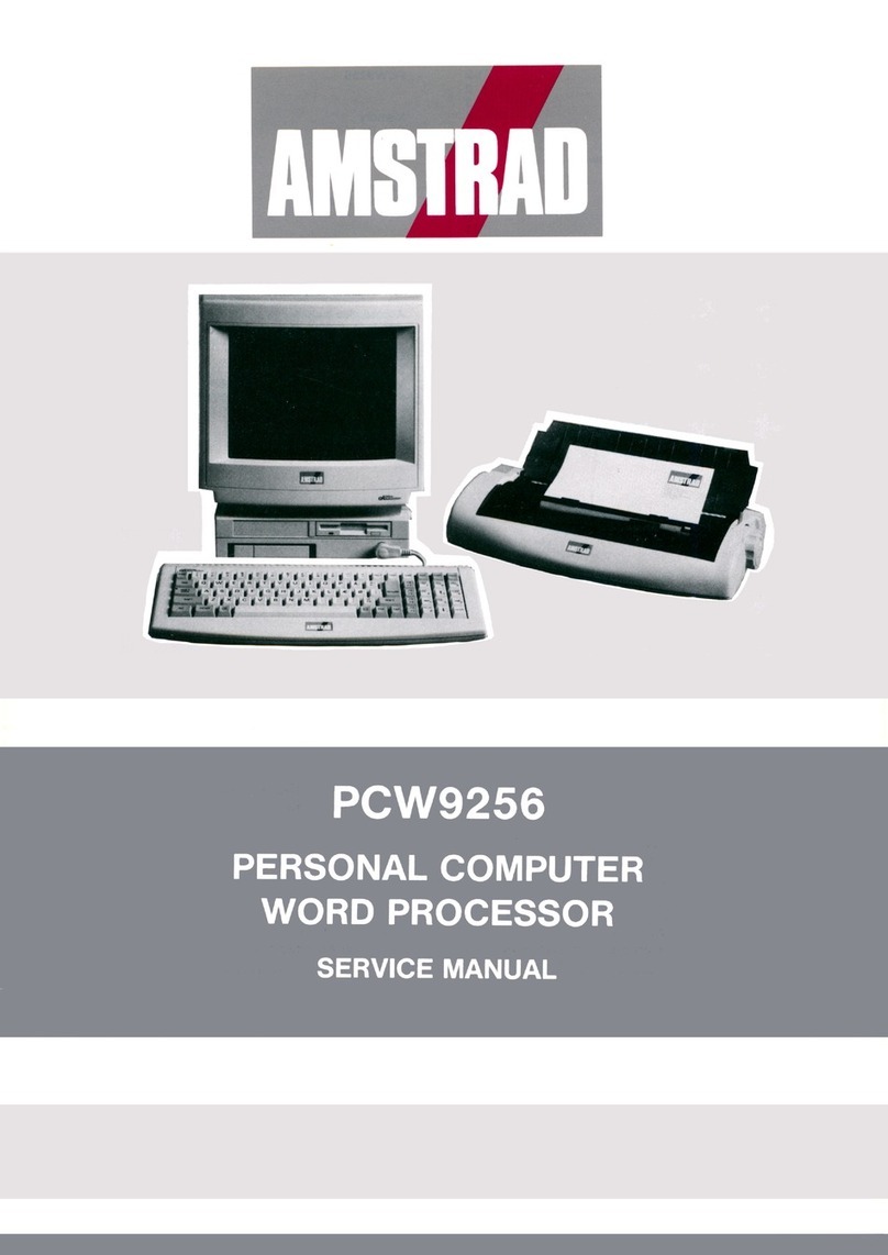
AMSTRAD PCW9256 User manual

AMSTRAD

AMSTRAD PCW9256 User manual

AMSTRAD Notepad NC100 User manual

AMSTRAD

AMSTRAD Notepad NC100 User manual

AMSTRAD PC1512 User manual

AMSTRAD

AMSTRAD PC1512 User manual

AMSTRAD PCW8256 User manual

AMSTRAD

AMSTRAD PCW8256 User manual

AMSTRAD CPC6128 User manual

AMSTRAD

AMSTRAD CPC6128 User manual
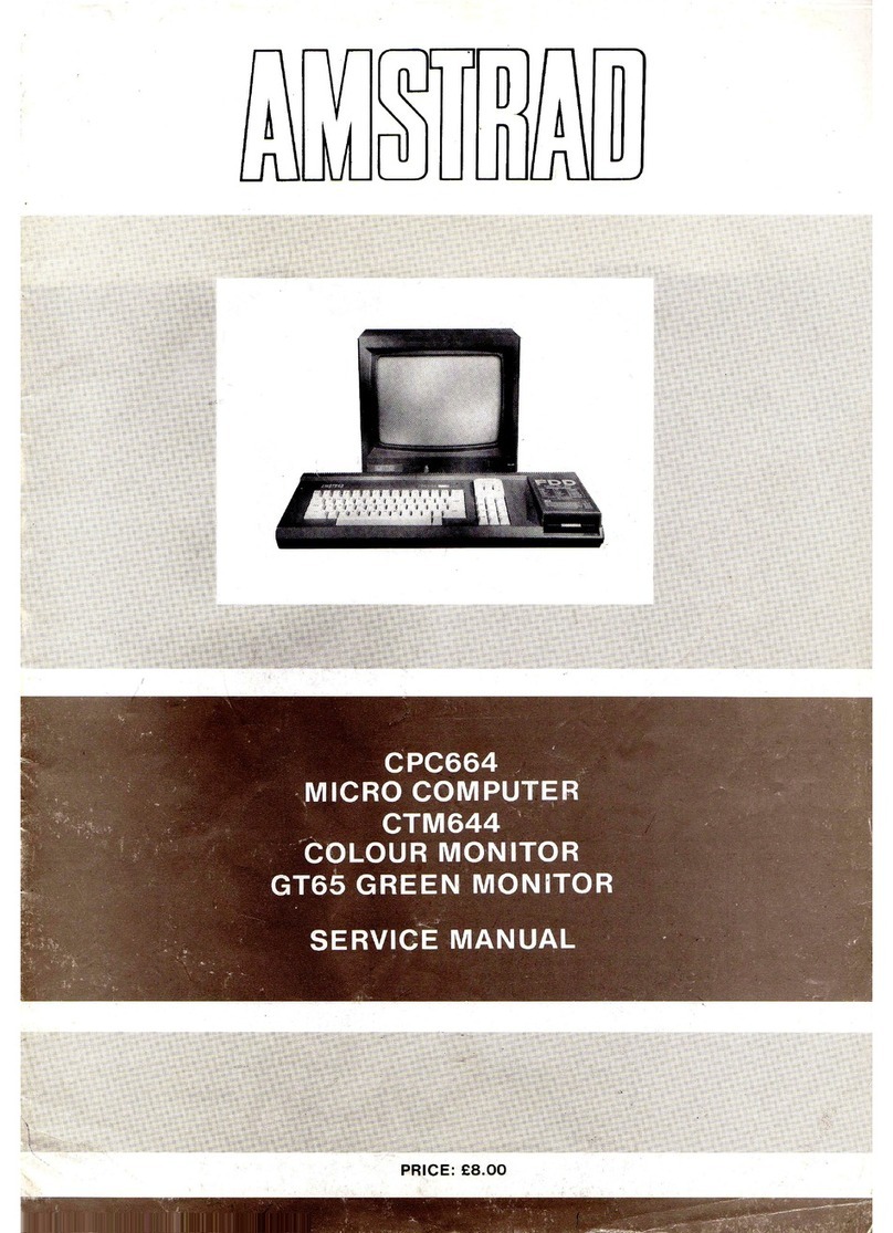
AMSTRAD CPC664 User manual

AMSTRAD

AMSTRAD CPC664 User manual

AMSTRAD CPC6128 User manual

AMSTRAD

AMSTRAD CPC6128 User manual

AMSTRAD CPC664 User manual

AMSTRAD

AMSTRAD CPC664 User manual

AMSTRAD CPC464 User manual

AMSTRAD

AMSTRAD CPC464 User manual

AMSTRAD CPC464 User manual

AMSTRAD

AMSTRAD CPC464 User manual

AMSTRAD TS80 User manual

AMSTRAD

AMSTRAD TS80 User manual

AMSTRAD PC1640 User manual

AMSTRAD

AMSTRAD PC1640 User manual

AMSTRAD CPC6128 User manual

AMSTRAD

AMSTRAD CPC6128 User manual

AMSTRAD CPC6128 Installation instructions

AMSTRAD

AMSTRAD CPC6128 Installation instructions

Popular Desktop manuals by other brands

Epson Equity IIe user guide

Epson

Epson Equity IIe user guide

Beckhoff CX50 0 Series Hardware documentation

Beckhoff

Beckhoff CX50 0 Series Hardware documentation

Toshiba TECRA C50-C Series user manual

Toshiba

Toshiba TECRA C50-C Series user manual

Compaq Presario S6000 - Desktop PC Quick setup

Compaq

Compaq Presario S6000 - Desktop PC Quick setup

HP Workstation xw8000 Hardware installation

HP

HP Workstation xw8000 Hardware installation

M5Stack POECAM manual

M5Stack

M5Stack POECAM manual

HP Pavilion a400 - Desktop PC specification

HP

HP Pavilion a400 - Desktop PC specification

Dell OptiPlex 3011 AIO manual

Dell

Dell OptiPlex 3011 AIO manual

Elo TouchSystems B-series user guide

Elo TouchSystems

Elo TouchSystems B-series user guide

Medion P2130 D quick start guide

Medion

Medion P2130 D quick start guide

Lenovo ThinkCentre A58 Användarhandbok

Lenovo

Lenovo ThinkCentre A58 Användarhandbok

Silicon Graphics IRIS Workstation user guide

Silicon Graphics

Silicon Graphics IRIS Workstation user guide

BOSER Technology BBS-2020 instruction manual

BOSER Technology

BOSER Technology BBS-2020 instruction manual

AT&T 3B2 Series Operation manual

AT&T

AT&T 3B2 Series Operation manual

Atari 520ST owner's manual

Atari

Atari 520ST owner's manual

conceptD 700 user manual

conceptD

conceptD 700 user manual

Kettler 07880-series Safety guide

Kettler

Kettler 07880-series Safety guide

HP Pavilion t400 - Desktop PC Technical specifications

HP

HP Pavilion t400 - Desktop PC Technical specifications

manuals.online logo
manuals.online logoBrands
  • About & Mission
  • Contact us
  • Privacy Policy
  • Terms and Conditions

Copyright 2025 Manuals.Online. All Rights Reserved.