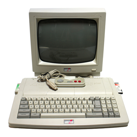
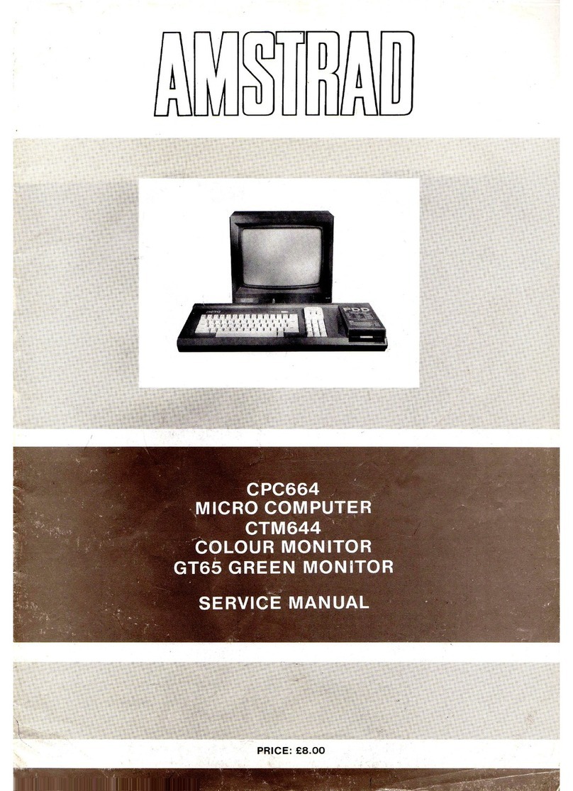
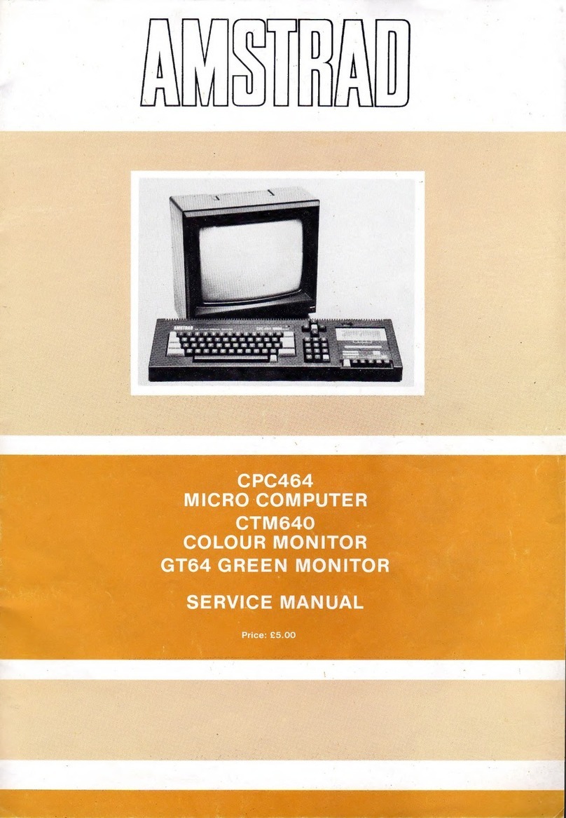
AMSTRAD CPC6128 User manual

:
£8.00
PRICE

CONTENTS
Page
Safety
Test
2
Keyboard
Exploded
View
and
Parts
List
3
CPC6128
Basic
Hardware
Analysis
4
Function
Diagrams
5
Function
Diagrams
6
Software
Errors
7
Diagnostic
Flow
Chart
8,9,10,11
Alignment
Checks
12,13,14,15
CPC6128
Main
PCB
16,17,18
CPC6128
CPU
Circuit
Diagram
19,20
Electrical
Parts
List
21
GT65
Exploded
View
and
Cabinet
Parts
List
22
GT65
Circuit
Diagram
and
Voltages
23
GT65
Main
PCB
and
Alignment
Instructions
24
GT65
Electrical
Parts
List
25
CTM644
Cabinet
Drawing
and
Electrical
Parts
List
26
CTM644
Electrical
Parts
List
and
Alignment
Instructions
27
CTM644
Electrical
Parts
List
and
Voltages
28
CTM644
Circuit
Diagram
29,30
Main
PCB
31,32
Interface
Circuit
Diagram
33,34
Disc
Control
Circuit
Diagram
35,36
Cassette
Control
Circuit
Diagram
36
Mechanism
and
Mechanical
Replacements
37
Technical
Specification
Back page
SAFETY
TEST
All
Monitors
are
safety
tested
to
the
following
specifications.
1).
Flash
Test
Test
at
3kV
between
the
live
and
neutral
of
the
mains
lead
joined
together
and
and
ALL
accessible
metal
points
on
the
exterior
of
the
set.
2).
Insulation
Resistance
Test
Test
between
the
live
and
neutral
of
the
mains
lead
joined
together
and
ALL
accessible
metal
points
on
the
exterior
of
the
set
to
show
a
resistance
of
at
least
4Mohm.
If
after
servicing
there
is
any
doubt
about
continued
electrical
safety
the
above
tests
should
be
carried
out.
AMSTRAD
CONSUMER
ELECTRONICS
PLC
BRENTWOOD
HOUSE,
169
KINGS
ROAD,
BRENTWOOD,
ESSEX
CM14
4EF.
Telephone:
Brentwood
(0277)
228888.
Telex:
995417
AMSELE
G.

KEYBOARD
EXPLODED
VIEW
KEYBOARD
PARTS
LIST
Cabinet
Top
Assembly
Frame
FDD
Knob
Volume
Cabinet
Bottom
Keyboard
Assembly
ESU-244
Compact
Floppy
Disc
Drive
EME-155
Volume
Rotary
K121LOZOT-20KB
Jack
RCA
3.5
HSJ1061-01-440
User
Port
Socket
HXC0730-01-010
Jack
DIN
TCS4450-01-101
Jack
DC
HEC0470-01-630
Jack
DIN
TCS4460-01-1011
Cord
DC
14550401
Relay
G4S-1112P-1-B-19
Cord
Connector
8W6Q004A
Speaker
CO40K01K2451
170855
170856
170806
170857
170858
190005
170807
170022
170023
170850
170024
170025
170822
170123
170862
170124
oOON
Onhwan—
-------@y

CONNECT
TO
240V
AC
MAINS
CPC6128
—
BASIC
HARDWARE
ANALYSIS
RED
LED
LIGHTS
REPLACE
MAINS
FUSE
CHECK
FOR
FAULTY
CABLE
OR
PLUG
ASSY
FROM
MONITOR)
CHECK
INTERNAL
FAULTY
LED
pec
aed
ad
BROKEN
PCB
TRACK
JOINTS
FAULTY
CONNECTER
CHECK
KEYBOARD
PCB
FOR
SIGNS
OF
ABUSE:
-
CRACKS
-
LIQUID
SPILLAGE
-
DISTORTED
MOUNTING
CHECK
CONNECTOR
LEAD
AND
TERMINATION
TEST
SWITCH
ON
COMPUTER
KEYBOARD
UNIT
REMEMBER
TO
TURN
BRIGHTNESS
UP!
FAULTY
SWITCH
RGB
VIDEO
ANY
YES
CONNECTOR
PICTURE
INSERTED.
AT
ALL
?
CHECK
IF
UNIT
STILL
TRY
KEYBOARD
REPLACE
OK
FAULTLY
SEEK
DISC
ANOTHER
SPECIALIST
CONNECTOR
DISC
ADVICE
NO
IMPROVEMENT
STILL
NOTHING
FAULTY
AUDIO
AMP
OR
SPEAKER
FAULTY
VOLUME
CONTROL
FAULTY
AUDIO
CONNECTOR
PLUG
/SOCKET
FAULTY
AY-3-8192
SOUND
IC
SEE
DISC
FLOW
CHARi
Full
diagnostic
tests
on
the
C.P.U.
can
be
carried
out
using
the
Amstrad
RP2
Test
Please
contact
Amstrad
PLC
for
information
on
same.
r
FAULTY
VIDEO
CONNECTOR
FAULTY
CABLE
ASSY
FAULTY
ULA
FAULTY
PCB
A.
XQ
r
CHECK
FAULTY
MONITOR
%
CABLE
TERMINATION
INTERNAL
CONNECTORS
%
BRIGHTNESS
CONTROL
FAULTY
ULA
Z80A
6845
CRYSTAL
RAM
Pack.

FUNCTION
DIAGRAMS
ICil4
Veo
82
6D
7D
72
6a
6D
5D.
50
OUTPUT
IQ
ID
2D 20
30
3D
4D
4Q
GN
CONROL
ss
ae
sane
ICi04.105
STROBE
A
16109.19
Yoo.
2a
SELECT
PATA
INPUTS
_
OUTP
uy
SE
ED
TE
2C3 202
2Cl
200
ey
-
iL
A
>
——
1G
L
A
bee
ic2_
tcl
ico
ty.
TTT
sy
lel
OBE
Bo
—_______.
OU
TP,
1G
SELECT
DATA
INPUTS
y
UTED
STR
INPUTS
OUTPUTS
{clot
Veo
DY
9
8
A
B
C
»D
BCD
-TO-DECIMAL
Qi
23456789
Lb
OUTPUTS
GND
1Ci06
vec
8@
8D
7D 7Q
6a 6D
5D
5a
CLOCK
CLEAR
1Q
ID
2D 28
3@
2D
4D 4@
ICS
Veo
2G
lyt
2Ad
1¥2
2A3
1Y3
2A2
(Yd
2Al
1G
1A]
2¥4
1A2
2Y3
1A2
2¥2
1A4
2Y!
GND
(CHO
Veo
4B
44
4Y
3B
3A BY
1A
1B
1Y
@A
2B
2Y
GND
ICH2
Voc
4B
4A
4Y 3B
3A
BY
iB
YY
2A 2B
2Y
GND

FUNCTION
FOR
A
MICROCOMPUTER
AND
IC's
IC108
Ic102
ANALOG
CHANNEL
C
TEST
Vee
ANALOG
CHANNEL
B
ANALOG
CHANNAL
A
Vss
1047
10A6
10A5
10A4
10A3
1042
IOA}
10A0
CPC6128
FUNCTION
DIAGRAMS
1C
107
{Cif
PA3
PAG
Au
Av)
yo
|Pae~l2]
Ba=PAS
|
Yo
ae
Ae~{2]
Aq
porr
al
Pay
[3]
pas
|
PORTA
Aa
48
PAO
(4
37]
P47
Aiaw-[4
47
READ
WRITE
inputs
RB
[5]
TR
AE
on
as~(5
mas
|
APRESS,
“Hecr
3
~[6
35]
RESET
s-6
Ge]
--45
5
INPUTS
GND
[7
4\~-Do
{
dav
7
=
PorT
{Ai
*|&
DI
DATA
|
pg-+[8
49
ADRESS
rol
BUS
INPUTS
(Ao
9
De
Ds~*[9
BZ]
~42
C7
10
~*D3
|
DATA
De
ua
pees
BASS
.
Al
+5v—[i/
40
|
{
ve
[2
GND
ue
PA
|
Dene
Aes:
RORTC
pos
(4
=
fry
|
CONTROL
we
f5
oe
CPU
ae
Pal
RESET
CF
pou
cpu
INT
>
5|+-BUSRQ
CPU
NMI
aa
[Bus
CONTROL|
NMi
—
WATT
CONTROL
Yo
HALT
—
BEAK
Vo
PORT
B
a
PORT
B
SYSTEM
MREQ
+
pe
a.
CONTROL]
JORG
+20]
2/]-RD
2
3
4 5 6
;
8
q
10
E+
{—§o,
DEL
|
’
y
YY
|
iii
(’
5
ESC]
Q
|TAB]
A
Panag
iF
ZT
a
7
7
¥
ig
O12
g
fife
[wl's
fo
fc
fi
sa
7a
a
a
a
e/5
|R|T/G]FiB
l
¢
S
8
Voc
RW/SEEK
LCT/DIR
FR/STP
‘HDL
RDY
WP/TS
FLT/TRo
PSo
PS1
WDA
USo
US,
HD
MFM
WE
vco
RD
RDW
WwCK

Software
Errors
if
a
drive
fault
is
reported
the
fault
may
be
a
software
problem.
Before
investigating
the
drive
please
carry
out
the
following
checks
to
ensure
it
is
not
a
software
problem.
Detection
and
Correction
of
‘‘Soft
Errors”
Soft
errors
are
usually
caused
by
the
following
reasons.
1)
Random
external
noise
of
several
usec
or
less.
2)
Minute
off-tracking
and
shifting
of
write
timing
that
are
not
detected
during
the
write
operation
which
can
cause
the
soft
error
during
the
read.
,
To
remedy
such
soft
errors,
take
the
following
procedures
at
the
controller
side.
1)
Repetitive
reading
on
the
track
by
10
times
or
more
until
the
data
is
restored.
2)
When
the
data
is
not
restored
by
step
1,
access
the
head
to
the
adjacent
track
in
the
same
direction
as
move
previously,
and
thereafter
return
the
head
to
the
original
track.
3)
Repeat
the
step
1.
4)
If
the
data
is
not
restored
by
the
above
steps,
the
error
cannot
be
remedied
Write
Error
When
an
error
is
caused
during
the
write
operation,
the
error
is
usually
detected
during
the
next
rotation
through
the
read
operation
called
“Write
check”.
To
correct
the
error,
repeat
the
write
operation
again
and
carry
out
the
Write
check.
If
the
result
is
still
incorrect
even
after
the
write
operation
is
repeated
more
than
10
times,
either
the
disc
or
the
drive
are
working
incorrectly.
To
find
out
the
trouble
source,
carry
out
the
read
operations
with
another
track.
Should
the
error
still
be
found,
change
the
disk
and
repeat
the
above
procedures.
Should
error
still
be
found,
the
drive
should
be
considered
defective.
If
the
error
is
removed,
the
original
disk
must
be
defective.
Discard
it.
Seek
Error
1)
Step
motor
or
step
motor
drive
circuit
is
defective.
2)
The
torque
of
the
carriage
is
not
correct.
Restoration
procedures
from
the
seek
error.
Make
the
re-calibration
to
the
track
OO.
Then,
carry
out
the
re-seek
to
the
original
track.
Notes:
1)
Always
ensure
the
head
is
clean.
2)
Index/Sector
Factor
(Ready
Defect)
As
the
unit
has
Optional
Read
Output
It
is
normally
not
ready
until
2
revolutions
are
made
after
the
disk
insertion.

Diagnostic
Flow
Chart
This
chart
must
be
used
in
conjunction
with
the
Alignment
Procedures.
This
chart
is
for
information
only
and
does
not
guarantee
an
exact
diagnosis.
For
warranty
purposes
any
faulty
drive
mechanism
must
be
returned
to
Amstrad
for
replacement.
Service
Agents
should
not
attempt
any
repairs
on
the
mechanism
or
to
its
P.C.B.
P.No.
30001.
Index
period
200+5msec?
Motor
rotation
Self-read
error?
Read
error
Write
error?
Write
error
Interchange-
Interchangeable
ability
error
lead?
Disk
Drive
O.K.

FLOW
CHART
(cont)
Motor
rotation
Does
motor
rotate?
Adjustable
with
VR201?
Adjust
to
20041ms
Does
it
rotate
normally
by
using
normal
motor?
Replace
motor
Power
supplied?
Check
wiring
Replace
drive

10
Test
with
disk
EME
-
CF2
TR39
2F
output
Z
140mVv?
lf
TROO
output
<
220mvV
Read/write
error
in
all
tracks?
Read
error
only
in
specific
track?
Replace
disk
(inspect
by
drive)
FLOW
CHART
(cont)
Is
head
touch
O.K.
Is
head
output
4mvV
or
more?
Replace
drive
Seek
error?
TROO
output
normal?
Replace
drive
Replace
drive
Replace
head
assembly
Replace
drive
Replace
TROO
sensor

FLOW
CHART
(CONT)
Write
error
N
Error
continuous?
Y
Write
waveform
OK
Check
action
in
TP1,
2?
in
seek
failure
Lo:
flow
NG
OK
Open
Head
connector
Check
action
Head
system
open
or
short?
in
read
failure
;
flow
Short
Amplifier
system
|
Repair
Replace
Replace
drive
|
head
connector
control
PCB
Interchangeable
lead
error
®
Off-track
media
lead
test
©Off-track
media
lead
test
Adjust
positioning
N
Index
timing
0
-
1000usec
Media
failure
_
Adjust
index
timing

12
The
data
contained
in
the
following
4
pages
is
for
information
only.
Service
Agents
must
not
carry
out
any
repair
or
adjustment
to
the
Drive
mechanism
and
its
associated
PCB
30001
during
warranty.
Fauity
mechanism
must
be
returned
to
AMSTRAD
for
exchange.
Alignment
Checks
Please
use
this
this
information
in
conjunction
with
the
diagnostic
flow
chart.
Equipment
required:
Double
Beam
Scope;
EME
-
CF2
Test
Disk
(please
refer
to
disk
notes
for
usage).
The
following
checks
can
be
carried
out
in
routine
servicing.
If
the
wave
patterns
do
not
appear
this
confirms
a
fault
with
the
mechanism.
Before
attempting
any
replacement
check
these
waveforms
thoroughly.
Content
of
adjustment
and
checking
ieee
1.
Redial
adjustment
by
use
of
Track
19
(Fig.
1).
2.
Adjustment
of
the
index
burst
by
use
of
Track
39
(Fig.
2).
3.
Azimuth
check
by
use
of
Track
39
(Fig.
3-4).
List
of
Test
Points
Test
point
Name
of
signal
Read
signal
of
filter
outlet
Read
signal
of
filter
outlet
Signal
ground
TROO
sensor
output
Index
signal
Signal
ground
BLOCK
2
BLOCK
3
BLOCK
49
rr
|
ch
ree
500ps
200ms
(TOTAL
49
BLOCKS)
INDEX
INDEX
Fig.1
Waveform
of
119
(Servo
pattern)
300ps

ALIGNMENT
CHECKS
100
80
60
Amplitude
ratio
(%)
40
20
S00Opsec
Fig.
5-1
Index
burst
waveform
Inner:
b/a
x
100%
Outer:
a/b
x
100%
10
20 30
AO
50
Amount
of
Off-center
(p)
Fig.
5-2
Off-centre
calibration
curve
Fig.
5-3
Azimuth
burst
(Effective
width
of
read
head
is
180u)
-48°
-72'
+48
+72
-
BB}
O-
Fig.
5-4
shows
azimuth
burst
in
the
cases
of
azimuth
-12’,0’
and
+12.
13

ALIGNMENT
CHECKS
(cont)
ROTATION
MEDIA
300ps
2F
(125kHz)
TS
39
[INDEX
HOLE
INDEX
173
544'00"_
/
RECORDED
|
SIDE
|
Difference
between
Track
00
and
39
is
within
I8ps
(2’)
Fig.
2
Waveform
of
T39
(Index
pattern
-
Radial
alignment)
2F(125kHz)
1.B
1
4
INDEX
Fig.
3
Waveform
of
1739
(Azimuth,
alignment)
12.0
05
35
0.5
3.5
0.5
oF
2F
IF
Track
center
Feil
EeTl
ig
m5
Py
ee
05
|||
03;
0.5]
O05]
O05)
0.5
2.0
{20
|
20
[20
10.0
3.5
3.5
7
: : ‘
0.5
QO.
0.5
+72'-
48'+48'-72
I
sot
so
\ \
i
=
BLOCK
1
BLOCK2
BLOCK
3
BLOCK
47
a
ors
ie
a
Index
Aximuth
burst
47
pair
servo-patters
for
positioning
use
burst
Fig.
4
Waveform
of
139

ALIGNMENT
CHECKS
(cont)
1)
Check
Positioning
1)
Load
CE
Disk.
2)
Set
up
track
OO,
Motor
off.
3)
Scope
to
TPS.
4)
Adjust
OO
Sensor
(8
on
Fig.
6)
so
that
scope
shows
correct
difference
as
Fig.
2.
2)
Adjustment
of
Index
Timing
1)
Load
the
CE
Disk
(refer
to
disk
info)
2)
Step
the
disk
to
the
track
39.
3)
Synchronise
the
oscilloscope
by
TP9
(INDEX).
Set
the
time
base
to
0.1msec/DIV.
4)
Connect
the
probe
to
TP1.
Connect
the
ground
probe
to
TP3
and
TP11
(ground)
of
PCB.
Set
the
input
to
AC
and
set
the
vertical
axis
to
20mV/DIV.
5)
Measure
timing
between
sweep
start
and
an
initial
data
pulse.
It
should
be
500
usec
+500
usec.
When
the
timing
is
not
within
this
range,
proceed
with
the
following
adjustment.
(Refer
to
Fig.
5-1).
6)
Loosen
the
tw”,
screws
fixed
LED
printed
board.
Adjust
the
position
of
LED
printed
board
so
that
the
timing
is
500
usec
+
100
usec.
7)
Re-check
the
timing.
8)
Seek
to
the
track
OO
and
make
sure
that
the
timing
is
within
500
usec
+
200
usec.
Tighten
the
screws.
(Fig.
5
-
1).
3)
Check
of
Head
Output
This
check
is
effective
only
when
making
write
and
read
check
as
described
below.
If
the
outputlevelis
less
than
the
prescribed
output,
clean
the
head
before
check.
Disk
used
for
this
check
must
be
in
good
condition.
1)
Load
the
CE
Disk.
2)
Select
track
39.
3)
Connect
one
of
the
probes
of
the
oscilloscope
to
TP1
of
the
printed
circuit
board,
another
probe
to
TP2,
and
the
probe
to
ground
to
TP3,
TP11
(ground).
Invert
one
channel,
and
set
it
to
Add
input,
set
input
to
AC,
and
set
the
vertical
axis
to
50mV/DIV
and
the
horizontal
axis
to
20msec/DIV.
4)
Make
sure
tha
average
output
level
is
the
following
value
or
more:
140
mV
p-p
(SN
25dB
or
more)
If
the
output
is
less
than
the
above-described
value,
replace
the
head.
4)
Adjustment
of
Positioning
1)
Load
CE
disk.
2)
Select
Track
19.
3)
Monitor
the
output
in
the
same
way
as
the
head
output
inspection.
Calculate
the
off-track
amount
in
reference
to
the
calibration
graph,
showing
the
interrelation
between
the
burst
amplitude
ratio
and
off-track
amount.
(Refer
to
Fig.
5-2).
4)
The
average
of
amplitude
ratio
should
be
below
26
um.
If
it
is
not
within
this
range,
make
the
following
adjustment.
i)
Loosen
the
bolt
of
the
rotation
stopper
which
fixes
the
screw
shaft
(Fig.
6-3).
Rotate
the
screw
shaft
and
adjust
it
in
such
a
way
that
the
amplitude
ratio
may
become
below
15
uM.
Tentatively
set
the
bolt
at
that
position.
ii)
Make
the
to
track
step
to
the
inner
and
outer
circles
and
bring
it
to
the
original
position.
Make
sure
that
the
adjustment
is
all
right.
Then,
tighten
the
boi.
5)
Confirmation
of
Head
Azimuth
1)
Load
the
CE
Disk
2)
Select
Track
39.
3)
Synchronise
the
probe
of
the
oscilloscope
by
TP9
of
PCB
and
connect
another
probe
to
TP1,
and
the
probe
ground
to
TP3,
TP11
(ground).
Set
the
input
to
AC,
the
vertical
axis
to
10
mV/DIV,
and
the
horizontal
axis
to
0.5
msec/DIV.
Make
sure
that
the
two
outside
burst
waveforms
are
smaller
than
two
inside
burst
waveforms
as
shown
in
Fig.
5-3.
Note:
Signal
preceding
the
azimuth
burst
is
the
index
burst.
If
the
azimuth
is
still
incorrect
reeplace
the
head
assembly.
15

16
CPC6128
MAIN
PCB
SME,
SSS
53990
Ls
EERSTE
SRS
ALLELUIA
BBB
EBE
ESSN
17

19
CPC6128
CPU
CIRCUIT
DIAGRAM
or
~~—_——+-
havo)
SOUND
CLOCK
(1MHZ
>
a
ae:
b
=a
~3
aD
oe
=
=
re
=e
D?
<3
oleae
10
D?
AND
D6
AISOUT
2
fe
D6
A1@QUT
Sh
4>1
eel
i
|
am
PADDLE
PORT
a
25
G
——
ie
13
PADG
ed
aie
3
9
PIN
*D/
CONNECTOR
AB
14
74S
153
F
19
IND
AY-3-8912
§
SO ae
A?
|
34
atts]
aS
r
a=
SOUND
102
OR
7
;
Pe
FaHC1S9
36
5
eee
eae
—>2
oom
2
[tor
pres)
ol
Ai
[56
—
26
Rath
oe
>S
SPARE
FOR
64k
Fs
7
b?
280
are
ae
—p7FIRE
I
4
2?
D6
DATA
BUS
ES
Serine
>
|]ozm0
00
waa
|
1g
HJ
——
8
t+
>
4
RIGHT
0
PA/HAL
Towa
AS
t
os
a3
D4
>
2
DOWN
RAMOIS
CASI
38
HDS845SP
D2
2
00
Re
1@LBAC
AM
=
2
32
2)
PBCOMMON
|}
D2
ameao030
ae
Eas
ary
bo
Ms
t+
»—2
=
ae
7
CONTROLLER
als
Ta]
u0s
AupouT
Aa
oe
a
el
—
—
sous
asa
al
eel
mecca
aaa
XV
2
XQ
4
XS
XS
17
Xo
re
=
=
2
.
pes
<0)
}——[
513
yg
||
CPI01,
cPt02
f
0
oa
RYekos
EXPANSION
8US
BSE
aoe,
=
=
fe
|
eis
7
SRECTOR
a2
ees
13,
131
pops
16
YG
At
=
ERE
SD
a
el
SE
>
17
YS
oral)
Bee
8
CALL
QUT
FOR
128K
IN
FOR 64K
>
74L$132
OR
74HC132
>
19
Y3
R150
47
pacers
Ae
23
8
10
TORD
EN
_
3
a
D7
27
TOWR
8
R
HSYNC
g
NEE
Pret
VSYNC_DISPEN
Q
it
31
Bearer
n
|
WGTOR
COX
450
>
oe
ae
;
G
SOUND
H
€
RD
DATA
16{
8 9
43110]
11
S
ig
ee
leis
stalseal
iv]
tL
D
WR
DATA
2
14
bg
PORTO?
AQ
0
p7
&
24)
SND
vor
a7
AO
55
4
i
ne
ey
=
TC134
e
bs
75
D6 bo
pe
»—24o1
10133
us
<Q)
[27
|
Oo
OG
tLKs
2
14
Oo
Gy
KS
oS
Ic124
os
>
2
101328
OFF
HM4864U-2
ai
6
Ea
o
of
8
OFF
HM4864U-2
SYNC!
ghee
=
ag
g
8
edhe
ee
D4
»—2
10123
64K
K
1BIT
RAM
is
2
SAK
X)
FELT
ORAM
“sv?
Ag
OeS/LINKS
ad
TC131
ALL
PINS
EXCEPT
jainie.
4
TORD
ea
aie
D3
2
ALL.
PINS
EXCEPT
14
2
DATA
FULLY
PARALLEL
108
1OWR
DATA
FULLY,
PARALLEL
3
Ici3a
gigi
jiecwtonted
EXP
(EXPAN
2
i4
Olol
wo
3S
v
syne
SION
S
be
1c121
2
2
icie9
6
<8
PIN DIN
>
7
=
14
og
pd
ssw
SP
01
e—2
or
icr20
01
>—2101
icree
14
hele
a
2G
=
i
12
R126
1
BoM
oe
oe
po
»
=
10119
tS
w
po
Ploy
1c127
TAS
L
el
>t}
RED
N
x
wa
270
Zs
OM
Ic110
Ic110
wes
s x
ooo
oF
o
5
4
3%
KON
9
i
Pats
182}
|-74kS1
32
=|
=
a
is]
1]
4]
3
rsa)
ist
4
3
=
ze
pac
Su
CA
CPST
BANK
ONLY)
=|"
[ans
8
10
|
7aHe1sg
|
AHCI
S2
BE
&
2
ue
HEREIE
iis
a
|
18
Q
R28
2
ae
H>e
3 6
=(-
=
=
©
2ND
BANK
ONLY)
Tas
coe
>|
|
GREEN
alg
™
en?
L
p
Bi,
e
©)
3103
zs
=
NOTE
:SEPARATE
CAS
TO
EACH
BANK
FOR
&
ICS
g
34
270
On.8
2
Ss
Pa
OTHERWISE
SECOND
BAN
tS
;
=
Oro
7aHCUO4
RESET
STEREO
7
a
=
3]
9
sv
as
STEREO
COMPLETELY
PARALLEL
p
ins.
[ao
ame
§
2K
SOUND
q
WITH
FIRST
BANRe
06
74s244
fy
7
aN
(>
SGSRESEr
CONNECTOR
|['502
OS
I
SesTayparee
|
|
Blue
“sy
CSTEREO
JACK)
Ala
es
g
e+
F
a
vi
Wala
AI3
3
a
|
|
eTaT
=
&|
A12
oe
4
2
al
<{
5
ai
s|
s
S
aos
ss
Qala
ws
af
an
i
.
—
:
ARR
crore
aia
3
a
ag
a
|
rete
40
za)
=
CSV)
AD
a
ElE|
op
a8
ee
————
74.$82
OR
7AHC32
=
AN
aUSRG
DS
|
3
3
A10
a
pe
ee
INT
ne
D4
©
12
<OD
#8
aro:
AS
a
ae
NMI
vee
3
TI
R
37
28Ci81SY
Ag
g
4
S22.
READY
re
D2
TSK
RGR
35
é
A?
C101~c134
AQ
D1
D
19
ies
HS63130)
S39
GM
AS
«—38
1111
a
De
1X
34
(BO)
a4
me)
“
i6
Th
(4d)
OR
z)a
AS
;
Z8400APS
=
S
SUSAK
AG
DS
is
one
RAM_DIS.
<3)
24
HSG3170
ia
g
Buse
y
2
C
]
BUS)
S
8
ZC
SOCKET
643)
ad
ne
RE
B
S
Ph
23
eye
«Or
AQ
-
=
D>
WREG
Ic110
fice
D4
2
aa
RIS?
4)
Ps
7
2h
AT
74132
ROMEN
ee
me
Ss
28
ps
m1)
SYNE
RFSH
(42)
5
‘
y
ROM
DIS
wa
30
4]
|
eno
13
a
STROBE
(43)
ADY
cog
pe
40]
07
-
é
ie
pe
te
(HSV
camRi4t_
20
CSV)
ra)
f=)
DS
1104
PRINTER
tS
(41)
82
7
2S
ba
2
93
PORT
R1SS
<o
1
at
RESET
3
ie
a
i
nee
cadena
(50)
C4MHZ
CLOCK
>
S6
mee
£2
17
ses
DI
i
3
D0
CONN
IC?
rat
29),
20
28
dO
4
17D?
cn?
2.
Mi
629,
e117
Ae
as
632)
2t
36
ay
eee
pany
ee
6319
!
NOTE
:
Cc
329]
aoe
GND
<
‘a
13
12
TORQ
(3m)
R144
3p
%
IC
40007-K
AND
IC
40010
TOWR
2444658410
One
5
a
RT
—iige
==]
NINTERRUPT
ARE
ALTERNATIVES
-INSTALL
mal
cae
ATI2
1201401Gs20«
27
ah
5
=<
:
a
exer
ONE
OR
THE
OTHER
BUT
NOT
BOTH.
30
<0)
X10,
60)
<a)
ROMEN,
£423
27
saa
3
TOWR
:
»
He=18
ROMEN,
NROMEN
4
6
7
ioe
EXPANSION
CONNECTOR
SOWAY
Q.1"
EDGE
CONN
R1S4
(+5V
>
447K
@
|
0
RO.
wi
icra
|
$
Pca
@2x33%31)
CHS-CMOS
—»USE)
2345
6 7
8
9
1011
121314
15
16 17 18
9
2
2
22
Ze
24
28
28
27
28
2A
30
Bt
82
3h
Me
ae
eS
A
4y
ee
47
48
49
50
MCCOOSA
SOUND
AIS
ATS)
AIT
AD
AP
AS
AB
ANS
n 1
)
WR__INT_@USRG_READY
RESET
1S
L
PEN
GND
A412)
AMO
ABsABSCOAsCi
A
sCiGsCititisisCRE
SRS
ORAL
BUS
ROMEN RAMRD
CURSOR
EXP
gf
CHASSIS
SCHEMATIC
DIAGRAM
RESET
NOTE:
THIS
SCHEMATIC
OLAGRAM
IS
THE
LATEST
AT
THE
TIME
OF
PRINTING
AND
SUBJECT
TO
CHANGE
WITHOUT
NOTICE.
M206-01
1-3583

Carbon
Film
Resistors
47ohm
R146-153,
161,
162
560hm
R155,
306
82o0hm
R141
1500hm
R136
1800hm
R134
2200hm
R137
2700hm
R126,
128,
130
560ohm
R317
680o0hm
R125,
127,
129,
135,
157,
158
301
Tkohm
R113,
121-123,
132,
140,
211,
212,
216,
313, 315,
321
1k50hm
R124
2k2ohm
R102,
109,
110,
112,
214
3k30hm
R131
4k70hm
R144,
310,
323
10kohm
R114-117,
120, 133,
142,
217,
309,
312
18kohm
R308,
311
22kohm
R118,
119,
304,
305
47kohm
R302,
308,
307,
319,
320
470kohm
R314
1Mohm
R111
3M3o0hm
R101
10Mohm
R143,
145
4ohm7
“Vw
Fuse
R322
1000hm2W
R316
Ceramic
Capacitors
C137,
138
C139-141,
310
C313
C306
C101-135,
201-213
Electrolytic
Capacitors
TuF/SOV
C309,
311,
314,
317,
318
22uF/10V
C308
47uF/10V
C136,
303,
306
100uF/10V
C301,
304
C315
100uUF/16V
Polycarbonate
Capacitors
(All
working
voltage
50V
D.C.)
0.001uUF
0.01uUF
0.047
UF
0.068uF
0.1UF
Diodes
D101,
303,
304
D201
D301
D302
182472-HS
DS442XFA5
10E1
SLP-155B
(R)
ELECTRICAL
PARTS
LIST
10020
10022
10030
10036
10037
10040
10042
10050
10052
10061
10065
10069
10073
10077
10085
10091
10093
10101
10147
170867
170868
170866
170869
400107
170126
24004
24020
170217
170128
1409178
170129
170851
170115
170816
170865
170866
IC’s
IC101
IC102
IC103
10104,
105,
109
113
IC106
iC107
IC108
1IC110,
210
C111
C112,
207
IC114
IC115
IC116
IC117
C118
1C119-134
IC201
IC202
IC203
IC204
IC205
IC206,
208
IC209
C211
C212
IC213
IC301
IC302
Transistors
Q101
Q102,
301,
302
W303
Miscellaneous
J101
J102
J103
J104,
105
J106
J301
J302
VR301
CD302
cbD201
FDD201
NR101
NR201
RY301
SP301
X101
HD74LS145
AY-3-8912
TMM-23256P-1953
HD74LS153
HD74L8273
M5L8255AP-5
HD6845SP
HD74L8132
Z8400APS
HD74LS32
HD74LS373
HD74LS8244
HSG3130/3170
TC74HCUO4P
PAL
16L8AC
MSM3764-20RS
UPD765AC-2
FDC9216BT
SN74HC240N_
TMM-23128P-1851
DN74LS08
DN74LS38
DN74LS136
DN74LS27
DN74LS74
TC74HC161P
LA4140
LA6358S
28C2120Y
285C1815Y
25C950Y
Jack
DIN
Socket
D
Sub
9
Jack
RCA3.5
Socket
IC
20
Pin
DIL
Socket
IC
10
Pin
DIL
Jack
D.C.
Jack
DIN
Vol.
Rot.
20k
D.C.
Cord
Cord
Connector
Compact
Floppy
Disc
Drive
EME-155
R.
Network
Exb
P86222J
R.
Network
Exb
P87681J
Relay
G4S-1112P-1-B-19
Speaker
CO40KO1K2451
Crystal
HC-18RW
16MHz
No
part
numbers
are
given
for
any
parts
on
PCB30001,
should
there
be
any
electrical
fault
with
that
PCB
Service
Agents
shouid
return
the
whole
Disc
Drive
Mechanism
complete
with
the
PCB
for
replacement.
170113
170114
170448
170025
170023
170022
170021
170865
170024
170850
170807
170882
170862
190005
170860
170861
170123
170124
170859
21

GT65
CABINET
EXPLODED
VIEW
CAUTION!
PARTS
MARKED
#
MUST
NOT
BE
REMOVED
UNDER
NORMAL
CIRCUMSTANCES
GT65
CABINET
PARTS
LIST
Front
Cabinet
Cable
Clamp
Bracket
Cabinet
(
Bracket
Cabinet
(R)
Bracket
P.C.B.
(L)
Bracket
P.C.B.
(R)
C.R.T.
Green
Metal
Washer
C.R.T.
Fixing
Screw
C.R.T.
Deflection
Yoke
C.R.T.
Socket
Power
Tx.
Rear
Cabinet
Control
Knobs
Button
Power
On/Off
Switch
V.
Hold
Pot.
Contrast
Pot.
Brightness
Pot.
D.C.
Cord
DIN
Cord
D.C.
Jack
u
Metal
Shield
$/170832
170512/SH
170831
170502
170504
170503
170505
170506
170507
170508
170509
170510
170511
170513
170514
170515
170516
170833
170518
170519
170316
170317
170834

Lror
71011202
GT65
CIRCUIT
DIAGRAM
17
28
Lai
(7)
‘S
©
@
&
=|
§
ie
ea
aie
_
©)
Y
GREEN
MONITOR
DISPLAYTUBE
701
‘3100NB31
CHASSIS
SCHEMATIC
DIAGRAM
PCB7O1
MMOOO?
wee
Otay
xerrsa
wi
>t
te
49
{
weed
(NADL
BILD
Sze
DOOIAD!
1169
Sl
EEADL
pee
ise
élse
OF
PRINTING
AND
SUBJECT
TO
CHANGE
WITHOUT
NOTICE.
NOTE:
THIS
SCHEMATIC
DIAGRAM
IS
THE
LATEST
AT
THE
TIME
GT65
VOLTAGE
DATA
1C701
-
UPC1031H2
1-5.99V
DC
2-11.98V
DC
3-
10.86V
DC
4-10.45V
DC
-
20.1V
DC
1C502
-
L78MG
1-20.7V
DC
2-O0VDC
3-12.5V
DC
4-4.9V
DC
13.6V
DC
20.6V
DC
5.5V
DC
12.6V
DC
Q501
5.1V
DC
Q502
12.0V
DC
Q605
DANGEREUSES
AN
POINT
DE
YUE
SECURITE
ATTENTION
=
LES
PIECES
REPAREES
PAR
UN
A
ETANT
N’UTILISER
QUE
CELLES
DECRITES
DANS
LA
NOMENCLATURE
DES
PIECES.
CAUTION:
SINCE
THESE PARTS
MARKED
BY
A
ARE
CRITICAL
FOR
SAFETY
,
USE
ONES
DESCRIBED
GN
PARTS
LIST
ONLY.
2.2V
DC
39.5V
DC
2.0V
DC
Other manuals for CPC6128
4
This manual suits for next models
2
Table of contents
Other AMSTRAD Desktop manuals

AMSTRAD
AMSTRAD CPC464 User manual

AMSTRAD
AMSTRAD CPC464 User manual

AMSTRAD
AMSTRAD PC1640 User manual
AMSTRAD
AMSTRAD CPC6128 Installation instructions

AMSTRAD
AMSTRAD PCW9256 User manual

AMSTRAD
AMSTRAD 464 Plus User manual

AMSTRAD
AMSTRAD PC1512 User manual

AMSTRAD
AMSTRAD CPC464 User manual
AMSTRAD
AMSTRAD PCW8256 User manual

AMSTRAD
AMSTRAD CPC664 User manual