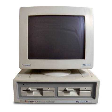
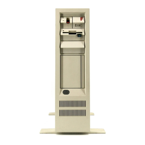
AMSTRAD PC1640 User manual

IBM
PC1640
PERSONAL COMPUTER
PC-MD
MONOCHROME DISPLAY
PC-CD
COLOUR DISPLAY
PC-ECD
ENHANCED COLOUR DISPLAY
SERVICE MANUAL

CONTENTS
Technical Specification
Safety Tests
FD-3 Maintenance
Flow Charts
Hard Disc Installation Instructions
Switch Settings
Understanding bad sectors on ahard disc
Notes
Keyboard Exploded Diagram
Keyboard Control PCB Layout
Keyboard Schematic Diagram
PC1640 Electrical Parts List
PC1 640/SD/DD/HD20 Cabinet Drawing &Parts List
PC1640/SD/DD/HD20 CPU P.C. Board
PC1 640/SD/DD/HD20 CPU P.C. Board (Bottom View)
PC1640/SD/DD/HD20 Chassis Schematic Diagram
PC1 640/SD/DD/HD20 Chassis Schematic Diagram
PC1640/SD/DD/HD20 Chassis Schematic Diagram
PC1 640/SD/DD/HD20 Chassis Schematic Diagram
PC-MD Electrical Parts List
PC-MD Cabinet &Parts List
PC/MD Main/CRT/Volume P.C. Board
PC/MD Chassis Schematic Diagram -Power Supply
PC-MD Chassis Schematic Diagram
PC-MD Alignment Instructions
PC-CD Electrical Parts List
PC-CD Alignment Instructions
PC/CD Chassis Schematic Diagram •
PC/CD Chassis Schematic Diagram
PC/CD Main P.C. Board
PC/ECD Cabinet &Parts List
PC-ECD Electrical Parts List
PC-ECD Alignment Instructions
PC-ECD RGB P.C. Board
PC/ECD CRT P.C. Board
PC-ECD Relay P.C. Board
PC/ECD Main P.C. Board
PC/ECD Chassis Schematic Diagram
PC/ECD Chassis Schematic Diagram -
PC/ECD Chassis Schematic Diagram
Monitor
Power Supply
Monitor
-TTL Decoder
Power Supply
Monitor
Page
2
2
3- 14
15- 17
18
19
20
21 &22
23
24
24&25
26
27
28
29
30
31
32
33
34
35
35
36
37
38
39
40
40
41
41
42
43
44
45
46
47
48
48
48
49
50
51
52
TECHNICAL SPECIFICATION
Internal Graphics Adaptor, fully compatible
640K system unit with all circuitry on asingle motherboard
8MHz 8086 processor
Three full-size compatible expansion slots (even with hard disc
option)
One or two 360K 5'A" floppy disks or one floppy with a20
Megabyte hard disk drive.
RS232 serial and parallel interface with standard connectors.
Loudspeaker with volume control.
Battery back-up real time clock and configuration RAM.
Socket for 8087 maths co-processor
Connector for light pen and/or joystick.
Full sized keyboard.
Numlock and Capslock.
Keyboard joystick port.
Two-button mouse with dedicated port on system unit.
Choice of one of three displays (paper-white mono, colour,
enhanced colour) with standard video connector.
ECD monitor has .31 mm pitch shadow mask.
CD monitor has .42mm pitch shadow mask.
Internal Graphics Adaptor provides:
Mono(MD):
80 column high resolution text with 9x14 dot characters.
EGA compatible Monochrome graphics 640 x350 lines.
Colour (CD):
(for use with CGA and 200-line EGA software)
40/80 column text with 8x8 dot characters in 16colours.
Medium resolution graphics 320 x200 lines in 4colours.
High resolution colour graphics 640 x200 lines in 2or 16col^
Enhanced Colour (ECD):
40/80 column text with 8x14 or 8x8dot characters in 16
colours.
High resolution colour graphics 640 x200 lines in 2or 16
colours.
Extra-high resolution graphics 640 x350 lines in 16 out of 64
colours.
oIum^
Dimensions (approx):
Monitors (Unboxed)
PC-MD
PC-CD
PC-ECD
System Unit
Gross Weights (approx):
Monitors
PC-MD
PC-CD
PC-ECD
System Unit
PC-SD
PC-DD
PC-HD
WIDTH
350mm
370mm
370mm
370mm
HEIGHT
315mm
320mm
320mm
135mm
(Boxed) 9.0Kg
13.5 Kg
13.5 Kg
DEPTH
300mm
360mm
360mm
384mm
(Unboxed)
8.0Kg
11.5Kg
11.5Kg
(Boxed) (Unboxed)
8.9Kg
10.5 Kg
11.0Kg
Keyboard (Boxed with
system unit)
5.0Kg
5. 8Kg
e^QKg
SAFETY TEST
All monitors are tested to the following specifications.
1.Flash Test: Test at 1.5kV RMS /3sec between the live and neutral poles of the mains lead and
all accessible metal points on the exterior of the set.
2. Insulation Resistance Test: Test at 1.5kV RMS /3sec between the live and neutral poles of the
mains lead and all accessible metal points on the exterior of the set to show aresistance greater
than 4Mohms.
3. Earth Continuity Test: The resistance of the mains lead shall not exceed 0.5ohms.
PLEASE NOTE: When any work is completed on this unit, correct safety tests must be carried out
to ensure continued electrical safety.
PLEASE NOTE: All parts shown with the part number prefix /'\ are Safety Items and must be
replaced with similar items having an identical safety specification.
All those items may be purchased direct from AMSTRAD pic.
AMSTRAD PLC
BRENTWOOD HOUSE, 169 KINGS ROAD, BRENTWOOD, ESSEX CM14 4EF.
TELEPHONE: 0277 230222. TELEGRAMS: AMSELEC BRENTWOOD. TELEX: 995417 AMSELE G.
In keeping with our policy of continually improving our service, and the technical quality of our products, we reserve the right to change component types,
manufacturers, sources of supply or technical specification at any time.

ittist
yv
NOTE
The flow charts are for information only and for warranty purposes any faulty drive mechanism must be returned to Amstrad
for replacement. Service Agents should not attempt to repair the mechanism.
Service Agents should note that the hard disc units are the most sophisticated mechanisms and should never be opened in
anormal environment. If any attempts are made to open the hard disc unit the guarantee is then invalidated and Amstrad
takes no responsibility to exchange the drive.
You should note further that there are two types of hard disc units in use i.e. Alps and Tandon. When ordering the
replacement units make sure that the Part No. is either 175037 for the Alps drive or 60001 for the Tandon drive. This
information applies only to the 20MB drives.
Amstrad reserves the right to ammend the circuit or change the components without prior warning.
Use RP4 diagnostics expansion card or diagnostic disc for fault findings.
FD3 MAINTENANCE
1. Introduction
This maintenance manual is for the maintanance FD3
1-1 General
The floppy disk Drive is ahigh precision equipment and requires the following Special Jigs, Tools, measuring
instruments and Adjustment when repairing or changing parts.
2. Special Jigs, Tools and Measuring Instruments
2-1 List of Special Jigs and Tools
CE diskette Dysan 224/2A
Blank diskette
Cleaning diskette
2-2 List of Measuring Instruments
Oscilloscope
Brian
Frequency Counter
2-3 CE Diskette (Alignment Diskette)
This Diskette is used for the following adjustments and checks.
R/W head radial position
R/W head azimuth
Index burst timing
3. Diagnosis Procedure
3-1 General
Hard errors are often caused by an incorrect procedure erroneous programing or damaged diskette, and soft
errors are often caused by dirty air or random electric noise. And other external factors are often considered to
be drive failure or incorrect adjustment. Check that errors are repeatedly produced with the first diskette and
that similar errors are also produced with other diskettes, unless obvious assembly trouble or damage are
found in visual inspection.
3-2 Soft Error Detection and Correction
Soft errors are generally caused by the following.
1) Dirty air between the R/W Head and Disk. Normally this dirt is cleaned out by the liner in the diskette.
2) Random electrical noise less than several microseconds.
3) Delicate track misalignment and writing timing misalignment, these are not detected during writing, and may
cause soft errors during reading.
4) Incorrect ground of the drive or host system power supply.
5) Incorrect spindle speed.
The following actions are required on the control side to recover the foregoing soft errors.
1) Reread the track ten times or until data recovered.
2) Access the head to an adjacent track if the error is not recovered by step (1) then return the head to the
previous track.
3) Repeat step (1).
4) Recalibrate the head then access the previous track and repeat step (1).
5) An error that cannot be recovered after taking these steps cannot be recovered.
3-3 Write Error
Operate READ-AFTER-WRITE if an error occurs during the write operation.
If the error cannot be recovered after operating READ-AFTER-WRITE more than four times, operate READ-
AFTER-WRITE on another track to determine whether the diskette or the drive is responsible for the error. If the
same error occurs on another track, change the diskette and repeat these steps. If the error still occurs, the
drive has some fault. If the error does not occur, the diskette is defective.
3-4 Read Error
Most errors are soft errors. Data can be recovered by following the recovery steps 3-2.
3-5 Seek Error
If seek error occurs, recalibrate the head then access target track once more.
If seek error occurs again, the drive has some faults.
Most seek errors are caused by stepping motor trouble or stepping motor drive circuit trouble.
3-6 Compatibility Error
In some cases, data written by one drive cannot be read by another drive.
This is due to the following reasons:
The check points are listed below.
1) Incorrect alignment —5-2
2) The head output is low —5-6
3) Motor speed irregularity —5-1
4) Check if the recommended sector format is set up.

3-7 List of Test Points (See Fig. 3-7)
Test Point Signal Name rTP 9-—-4-
r111r1
1
TP1 READ AMP OUT
+
TP2 READ AMP OUT
-
TP3 GND
TP4 STEP
TP5 READ DATA
TP6 INDEX
TP7 WRITE PROTECT
TP8 TRACK 00
TP9 GND
I
Fig. 3-7 Test Point Layout
4. Parts Exchange
4-1 Printed Circuit Board Exchange (See Fig. 4-1)
4-1-1 Printed Circuit Board Removal
a)
b)
c)
d)
e)
Remove the drive belt, stretched between the spindle pulley and the DC motor pulley by rotating the spindle
pulley as the direction shown in Fig. 4-1. Be careful not to touch the inner surface of the drive belt and the side of
the spindle pulley and DC motor pulley.
Disconnect the connectors. (LED, P.C.B., Track 00 sensor, DC Motor P.C.B., Stepping Motor, Head F.P.C.).
Unfasten four printed circuit board fixing screws.
Remove the printed circuit board.
Remove the insulating sheet.
Fig. 4-1 Printed Circuit Board Exchange
*
4-1-2 Printed Circuit Board Mounting and Adjustment
a) Install the insulating sheet.
b) Fix the printed circuit board with four screws.
c) Reconnect the disconnected connectors, (LED, P.C.B., Track 00 sensor, DC motor P.C.B., Stepping motor,
Head F.P.C.).
d) Place the drive belt over the DC motor pulley completely and only partially on the spindle pulley.
e) By rotating the spindle pulley, the rest of the belt will fit completely over.

4-2 DC Motor P.C.B. Removal (See Fig. 4-2)
4-2-1 DC Motor P.C.B. Removal
a) Disconnect the connectors (Printed Circuit Board, DC Motor)
b) Unfasten two DC motor P.C.B. fixing screws.
c) Lift the right edge of the DC motor P.C.B. and pull it up.
Be careful not to touch the spindle pulley with DC motor P.C.B.
4-2-2 DC Motor P.C.B. Mounting and Adjustment.
a) Install the DC motor P.C.B.
b) Fix the DC motor P.C.B. with two screws.
c) Reconnect the disconnected connectors. (Printed Circuit Board, DC Motor).
Fig. 4-2 DC Motor P.C.B. Removal
4-3 Lever Exchange (See Fig. 4-3)
4-3-1 Lever Removal
a) Set the lever horizontally.
b) Unfasten the fixed screw of the lever.
c) Pull the lever forward.
4-3-2 Lever Mounting
a) Place the wide part of the clamp cam on the hub side and check that the lever shaft hole can be seen from
above. (Hub open state).
b) Set the lever horizontally and insert from the front.
c) Secure the lever with ascrew.
Fig. 4-3 Lever Exchange

4-4 Bezel Exchange (See Fig. 4-4)
4-4-1 Bezel Removal
a) Remove the lever as described in 4-3-1.
b) Unfasten two bezel fixing screws.
c) Pull the bezel forward.
4-4-2 Bezel Mounting
a) Insert the bezel from the front.
b) Secure the bezel with two screws.
c) Mount the lever as described in 4-3-2.
Fig. 4-4 Bezel Exchange
4-5 LED Assembly Exchange (See Fig. 4-5)
4-5-1 LED Assembly Removal
a) Disconnect the connectors. (Index sensor, W/P sensor and Printed Circuit Board).
b) Unfasten the LED Assembly fixing screw.
c) Pull it back.
4-5-2 LED Assembly Mounting and Adjustment
a) Install the LED Assembly by inserting the LED into the LED insertion hole on the bezel.
b) Fix the LED Assembly with a screw.
c) Reconnect the disconnected conectors. (Index sensor, W/P sensor and Printed Circuit Board).
Fig. 4-5 LED Assy Exchange

4-6 Ejector Assembly Exchange (See Fig 4-6)
4-6-1 Ejector Assembly Removal
a) Set the lever vertical (Clamp state).
b) Unfasten three cover fixing screws.
c) Remove the cover.
d) Insert protection paper (High quality white paper approximately 10x30 mm between the top head and bottom
head to protect them.
e) Unfasten two ejector assembly fixing screws.
f) Lift the top head carefully, (approximately 2-3mm) then remove the ejector assembly.
4-6-2 Ejector Assembly Mounting and Adjustment.
a) Lift the top head and insert the ejector assembly under the head arm.
b) Place the ejector assembly as two half punched bosses fit into the holes of the lever frame then secure the
ejector assembly with two screws.
c) Remove the protect sheet between the top head and bottom head.
d) Fix the cover with one short screw and two long screws.
(Short screw for inner hole).
m
AMI
Fig. 4-6 Ejector Assembly Exchange
4-7 Lever Frame Assembly Exchange (See Fig. 4-7)
4-7-1 Lever Frame Assembly Removal
a) Remove the lever as described in 4-3-1
.
b) Remove the bezel as described in 4-4-1.
c) Remove the LED assembly as described in 4-5-1
.
d) Remove the ejector assembly as described in 4-6-1
.
e) Unfasten four lever frame fixing screws.
f) Lift the lever frame assembly slightly making sure that the top head is not raised, and remove the lever frame
assembly by sliding it to the left.
4-7-2 Lever Frame Assembly Mounting and Adjustment
a) Lift the top head slightly and slide the pad mounting arm of the lever frame assembly under the top head.
b) Secure the lever frame assembly with four screws.
c) Mount the ejector assembly as described in 4-6-2.
d) Mount the LED assembly as described in 4-5-2.
e) Mount the bezel as described in 4-4-2.
f) Mount the lever as described in 4-3-2.
g) Turn the lever slowly until it stops. By this operating, the hub assembly is placed in the best position for
clamping automatically.
h) Adjust the index burst time. (Refer to 5-5).

Fig. 4-7 Lever Frame Assy Exchange #
Head Assembly Removal
Remove the lever as described in 4-3-1
.
Remove the bezel as described in 4-4-1.
Remove the LED assembly as described 4-5-1.
Remove the ejector assembly as described in 4-6-1.
Remove the lever frame assembly as described in 4-7-1
.
Disconnect the connectors (Head F.P.C.)
Unfasten the screws fixing the guide shaft keeper Aand B, then remove keeper Aand B.
Hold the bottom head and lift the head assembly slightly then carefully remove by sliding to the right.
Remove the guide shaft from the head assembly in backward direction.
Head Assembly Mounting and Adjustment
Insert the guide shaft into head assembly and mount on the chassis so that the follower pin of the head
assembly fits into the screw of the screw shaft of the stepping motor assembly by sliding to the left.
Secure guide shaft keeper Aand Bwith two screws.
Reconnect the disconnected connectors (head F.P.C).
Mount the lever Frame assembly as described in 4-7-2.
Mount the ejector assembly as described in 4-6-2.
Mount the LED assembly as described in 4-5-2.
Mount the bezel as described in 4-4-2.
Mount the lever as described in 4-3-2.
Adjust the radial track alignment (5-2), index burst time (5-5), trackOO sensor timing (5-3), head azimuth (5-4),
resolution (5-7) and symmetry (5-8) after head mounting.
8
Fig. 4-8 Head Assy Exchange

4-9 Stepping Motor Assembly Exchange (See Fig. 4-9)
4-9-1 Stepping Motor Assembly Removal
a) Remove the lever as described in 4-3-1.
b) Remove the bezel as described in 4-4-1.
c) Remove the LED assembly as described in 4-5-1.
d) Remove the ejector assembly as described in 4-6-1.
e) Remove the lever frame assembly as described in 4-7-1.
f) Remove the head assembly as described in 4-8-1.
g) Disconnect the connector (stepping motor).
h) Unfasten two stepping motor fixing screws.
i) Remove the stepping motor assembly. Be careful not to touch the screw shaft of the stepping motor.
4-9-2 Stepping Motor Assembly Mounting and Adjustment
a) Install the stepping motor assembly in the chassis, and fix with two screws.
b) Reconnect the disconnected connector (stepping motor).
c) Mount the head assembly as described in 4-8-2.
d) Mount the lever frame assembly as described in 4-7-2.
e) Mount the ejector assembly as described in 4-6-2.
f) Mount the LED assembly as described in 4-5-2.
g) Mount the bezel as described in 4-4-2.
h) Mount the lever as described in 4-3-2.
i) Adjust the radial track alignment (5-2), index burst time (5-5), trackOO sensor timing (5-3), head azimuth (5-4),
resolution (5-7) and symmetry (5-8) after mounting.
*
«tk
Fig £-9 Stepping Motor Assy Exchange
4-1 DC Motor Assembly Exchange (See Fig. 4-1 0)
4-10-1 DC Motor Assembly Removal
a) Remove the drive belt as described in 4-1-1 a)
b) Disconnect the connector (DC Motor)
c) Unfasten two DC motor assembly fixing screws.
d) Remove the DC motor assembly.
4-10-2 DC Motor Assembly Mounting and Adjustment
a) Secure the DC Motor assembly with two screws.
b) Reconnect the disconnected connector (DC Motor).
c) Replace the drive belt as described in 4-1-2 d), e).
d) Adjust the spindle speed (5-1) after mounting.

Fig. 4-10 DC Motor Assy Exchange
4-1
1
TrackOO Sensor Assembly Exchange (See Fig. 4-1 1)
a) Unfasten three cover fixing screws.
b) Remove the cover.
c) Disconnect the connector (trackOO sensor).
d) Unfasten trackOO sensor assembly fixing screws
e) Remove the trackOO sensor assembly
4-1 1-2 TrackOO Sensor Assembly Mounting and Adjustment
a) Mount the trackOO sensor assembly with ascrew.
b) Reconnect the disconnected connector (trackOO sensor).
c) Fix the cover with one short screw and two long screws, (short screw for inner hole)
d) Adjust the trackOO sensor after mounting (refer to 5-3).
^
Fig. 4-11 TrackOO Sensor Assy Exchange
10

5. Adjustment and Check
5-1 Spindle Speed Adjustment (See Fig. 5-1)
a) Insert and clamp ablank diskette while DC motor is rotating.
b) Move the head to trackOO.
c) Connect the frequency counter to TP6
d) Check that counter shows 200±3ms.
e) If the counter value shows out of range, turn the variable resistor (VR1 )on DC motor board locates bottom of
drive. Spindle speed goes slower by turning to the left, faster to the right.
f) If the counter value shows out of range after taking method (e), exchange the drive belt and repeat from (d).
g) If the counter value still shows out of range after exchanging the drive belt, exchange the DC motor and/or DC
motor board.
VR1
Fig. 5-1 Spindle Speed Adjustment
5-2
a)
b)
c)
d)
Radial Track Adjustment (See Fig. 5-2)
Insert and clamp aCE diskette.
Move the head to track 16and check the cat's-eye waveform of the top and bottom heads.
Adjust as follows if one of the top or bottom head is not more than 75% in an amplitude ratio of two waveform.
Slightly loosen the fixed screws of the stepping motor assembly and move the stepping motor back or forward
to adjust the amplitude ratio. The amplitude of two wave forms should be nearly the same, then tighten the
stepping motor assembly fixing screw.
Check the cat's-eye waveform of top and bottom heads.
Repeat from (d) if adjustment fails.
Measuring Condition
Channel 1-TP1 (10mv/div)
Channel 2-TP2 (10mv/div), invert
Mode -ADD
Sweep -20ms/div
Stepping Motor Assy
-^ X100 75 'A
Fig. 5-2 Radial Track Adjustment 11

5-3 TrackOO Adjustment
a) Insert aCE diskette
b) Continuously seek between trackOO and track02 at the minimum access time between tracks of DFD222A
specifications.
c) Adjust trackOO sensor assembly so that the step signal and trackOO signal are on the timing as shown in Fig. 5-
3. The secure with the fixed screw.
Measuring condition
Channel 1-TP4 (0.2V/div)
Channel 2-TP8 (0.2V/div)
Mode -DUAL
Sweep -10ms/div TK02 TKOI TKOO TKOI TK02
Step signal ~LT uuU
TKOO signal
kb
<-*-> -*
rDirection r
The minimum access time between tracks a b
6ms/track 3ms max 8ms max •
Fig. 5-3 TrackOO Adjustment
5-4 Azimuth Check
a) Insert and clamp aCE diskette.
b) Move the heads to track 34 and check with third waveform set if azimuth waveforms of top and bottom heads
are as described in Fig. 5-4.
c) Exchange the head assembly if the azimuth of one of the top or bottom head is not as shown in Fig. 5-4.
Measuring condition
Channel 1-TP1 (10mv/div)
Channel 2-TP2 (10mv/div), invert
Mode -ADD
Sweep -1 ms/div
Trigger -TP6 *
1) When a>d (negative) 2) When a<d (positive)
bc
Shows Ominute
ab
a=b
cd
Shows misalignment by -18' Shows misalignment by +18'
12 Head azimuth =0±18'

5-5 Index Burst Time Adjustment
a) Insert and clamp aCE diskette.
b) Move the head to track 34 and check the index burst time of the top and bottom heads. Adjust if the timing of
one of the top or bottom head is not as shown in Fig. 5-5.
c) Move the index sensor assembly back or forward by slightly loosening the index sensor assembly fixing
screw to adjust the index burst time, then secure with the screw.
d) Check the index burst time of the top and bottom heads.
e) Repeat from (c) if adjustment fails.
Index
Measuring condition
Channel 1-TP1 (10mv/div)
Channel 2-TP2 (10mv/div), invert
Mode -ADD
Sweep -100 us/div
Trigger -Edge connector J2 -8, slope
Ifew Reading
Output Signal
Screw
Index Sensor '
/ui®iuBl-H i-jr®ufD
he
T=200 ±200 /is
qA
Fig. 5-5 Index Burst Time Adjustment
5-6 Lever Check
a) Insert and clamp ablank diskette.
b) Move the heads to track 39 and write 2F by the top and bottom heads.
c) Check that the average output levels of the top and bottom head is more than 270mV. Perform the following if
the output level is below the required standard.
d) Insert another blank diskette and reconfirm.
e) Check the spindle speed as described in 5-1.
f) Change the oscilloscope mode to the CHOP mode and check the TP1 andTP2 outputs. Exchange the printed
circuit board of one output is smaller than another one or missing, even though the probes are normal.
g) Exchange the head assembly if no problems are encountered in (d), (e).
Measuring condition
Channel 1-TP1 (10mv/div)
Channel 2-TP2 (10mv/div), invert
Mode -ADD
Sweep -20ms/div
Trigger -TP6
Head Reading Output Signal (TP1-TP2;
A=270mV min.
Fig. 5-6 Level Check 13

5-7 Resolution Check
a) Insert and clamp ablack diskette.
b) Move the heads to track 39, write 1Fand 2F by the top head and measure the average output level of each
frequency.
c) Write 1Fand 2F by the bottom head and measure the average output level of each frequency.
d) The resolution is higher than 55%, and calculation shall be made as follows:
Resolution =2F output (mV)/1 Foutput (mV) x100
e) Move the heads to trackOO, write 1Fand 2F by the top head and measure the average output level of each
frequency.
f) Write 1Fand 2F by the bottom head and measure the average output level of each frequency.
g) The resolution is lower than 95%.
Measuring condition
Channel 1-TP1 (10mv/div)
Channel 2-TP2 (10mv/div), invert
Mode -ADD
Sweep -20ms/div
Trigger -TP6
5-8 Symmetry Check.
a) Insert and clamp ablank diskette.
b) Move the heads to trackOO and write 1Fby the top and bottom heads.
c) Check the symmetry as described in Fig. 5-8.
d) Exchange the head assembly if the symmetry is out of the range as described in Fig. 5-8 on only one head
side.
e) Exchange the printed circuit board if symmetry is out of the range on both heads.
f) If the symmetry is still out of the range, exchange head assembly or printed circuit board that was not
exchanged on the previous step.
•4
TP5
(Read data) Trigger
-»i-U-
T=400"s or less
*,
Fig. 5-8 Symmetry Check
Measuring condition
Channel 1-TP1 (0.1V/div)
Channel 2-NC
Mode -CH1
Sweep -0.5 us/div
Trigger -INTERNAL, Slope =(+)
5-9 Write Protect Sensor Check
a) Load and unload ablank diskette which is not write protected, and check that write protect sensing is
definitely made using Brian.
b) If the write protect sensing does not work well, exchange lever frame assembly according to 4-7.
c) Repeat from (a).
5-10 Head Cleaning
a) If you tend to clean the heads, use the special diskette which is sold as "cleaing diskette". We would
recommend the wet type cleaning diskette that uses "cleaning liquid".
14

Trouble
3E
See error command
of FDC.
See this maintenance
maunal to other
mechanical troubles.
NO
YFS
MO
YES
->-
->- Change LED
Is write protect
signal received?
Medium may be
damaged. U—YES —
NO
Cannot
write
-YES >~
Does it write if
medium is changed?
Y
NO
\/
Is write
protect seal stuck
on medium?
NO
V
YES
Write protect sensor has
failed. Check write
protect circuit and its
periphery.
is head cord damaged
or disconnected?
V
NO
Remove seal
YES
Exchange head
Is write gate
correctly opened?
YES
NO Check circuit
check system
Is setting
appropriate?
YES
NO Drive NG
(stepping motor)
Check circuit 15

V
Is termination
resistor correctly
attached?
NO Mount
correctly
YES
1_
Is environment
condition appropriate?
YES
1_
NO ^> Set up environmental
condition appropriately
Are errors
caused after changing
to another medium?
NO Medium may
be faulty
YES
Is avery
large noise source
present?
YES Remove noise
source
NO
1
Is thefe
sufficient head
head pressure
NO MChange head
YES
A.
Are errors
caused on inner
circumference of
tracks?
NO
Is index
signal correctly sent?
.
•*
Y
\
ES
I
NO
Is azimuth
azimuth Tilting of guide shafts
due to shock, or heads
are defective
YES
Is seek
operation
normal?
NO -5* Check step motor and
driving mechanism
YES
Is time margin
of inner circumference
tracks sufficient?
YES
A*i
NO
YES
\y
Change the printed
circuit board. Change
the head if problem
is not solved.
Is power NO Check power
ripple noise
correctly fed?
Check data separator
on system side
YES
J±
Check circuit
(Read errors are caused)
16

FD-3 FLOWCHART
Are connectors
correctly plugged? NO Plug correctly
YES
Medium may
be faulty
Is short bar
setting correctly?
NO Set normally
YES
YES
YES
JiH
Is medium
rotating? NO
Does it read
if changed to
another medium7
«NO
A.
Is alignment
OK? -NO
Jil<L
Does cariage
operate properly7NO. Check step motor
and circuit head
driving mechanism
operating step
motor.
YES
Does read
waveform show
after adjustment?
YES Adjustment,
alignment
M^
Is power fed? NO- Check power
YES
1_
Does DC motor
operate?
(Apply 12V)
NO. Change DC motor
YES NO
Is spindle
speed OK? NO
V
Read circuit has
aproblem.
Exchange
MC3470AP.
Change printer
circuit board.
YES
Are cords
and wires correctly
connected7
NO. Correct
incorrect wiring.
YES Over-
speeding?
Is index signal
sent correctly? NO
V
I
YES
_y_
Is TRKOO OK7
YES
Check motor
control printed
circuit board. Is
servo cord
disconnected
from motor7
NO
V
NO
YES
1
Is motor start
time appropriate7V
NO
YES
Read circuit may
have problems.
Change MC3470AP.
Change printed
circuit board.
YES
iZ_
Operating
normally? YES
OK Is motor ON
signal sent? NO Check signal on
system side
Possibility of
or head cord
trouble.
YES
V
Is index sent7—NO
YES
±
Possibility of circuit
part faults. Adjust
centering motor-control
printed circuit board.
Adiust
Index sensor
is faulty
JL
Adjust
VAdjust Can it be
adjusted? -YES- OK
NO
Change motor Drive has problem
(Medium slip or
other reason). 17

HARD DISC INSTALLATION ON PC1640
PC1640 hard disc comes ready installed with the necessary software. That is discs 1to 4that are
supplied ready with the machine.
However in the case of adisc failure it may be necessary to reinstall the supplied software.
This is done in the following way:
1. Put disc one into drive A: and boot up the system.
2. Put disc four into drive A: and type CD\SUPPLEME and press return.
3. Type HDFORMAT and press return.
4. Answer YES to the screen prompt.
5. When HDFORMAT is completed remove disc four and replace with disc one.
6. Type CD\and press return.
7. Type FDISC and press return.
8. Press return every time you are asked aquestion.
9. With disc one still in drive A: type FORMAT C:/S and press return.
10. When formatting is finished replace disc one with disc four.
1 1
.
Type CD\SUPPLEME and press return.
12. Type CONFIG and press return.
»
After typing CONFIG the machine will proceed to copy the four system discs to the hard disc.
After copying each disc you will prompted to insert the next disc.
You do not need to know in which order to insert the discs because the machine will tell you which disc is
needed next.
The system is now installed and should be tested by rebooting the machine.
It should be noted that if the hard disc is ok but the software has been corrupted or deleted you can
reinstall the software without reformatting.
This is done by following steps 11and 12.
*\
18

IMPORTANT
PLEASE READ BEFORE SWITCHING ON
THE PC1 640 SYSTEM UNIT CAN BE USED WITH EITHER APC-MD MONOCHROME DISPLAY, APC-
CD COLOUR DISPLAY OR APC-ECD ENHANCED COLOUR DISPLAY. THERE IS A1POSITION DIP
SWITCH ATTHE BACK OF THE SYSTEM UNITTHAT MUST BE ADJUSTED FOR USE WITH EITHER OF
THE COLOUR DISPLAYS. PLEASE LOOK AT THE FOLLOWING CHART AND ADJUST THE DIP
SWITCHES ACCORDING TO THE DISPLAY YOU HAVE FOR SERVICE.
123DIP SWITCHES
45678910
PC-MD OFF OFF ON OFF ON ON ON OFF OFF OFF
PC-CD OFF OFF OFF ON ON ON ON OFF OFF OFF
PC-ECD OFF ON ON OFF OFF ON ON ON OFF OFF
DISPLAY SELECTOR SWITCH SETTINGS
The display selector switch settings determine how the IGA (Internal Graphics Adaptor) is configured
Jwhen the machine is powered on or reset. These switch settings can be overridden by software. In
^* particular by the DISPLAY command which is installed on all Hard Disc PCs and Disc 2of your system
discs. Many of the modes below have been given aname, unique to the Amstrad PC1 640, in order to
easily distinguish between them. These names are accepted by the DISPLAY command, which will
switch to the requested mode, or print an error message if it is not possible or advisable.
Mode Sw1 Sw2 Sw3 Sw4 Sw5 display Description
MDA or Hercules Diag (1)
EGA monochrome
CGA compatible 40 column
CGA compatible 80 column (2)
EGA compatible 40 column
CDA compatible 80 column
EGA 200 lines
EGA 350 lines (3)
MDTEXT off off on off on MD
MDMONO off off on off off MD
on off off on on CD
CDMONO off off off on on CD
on off off on off CD
CDCOLOR off off off on off CD
ECD200 on on on off off ECD
ECD350 off on on off off ECD
all modes: SW6 SW7 SW£
XXon -
off- PC ECD
PC MD or PC CD
SW9
off
SW10
off
(1) Recommended setting for PC MD
(2) Recommended setting for PC CD
(3) Recommended setting for PC ECD
x=don't care
19

UNDERSTANDING BAD SECTORS ON AHARD DISC
Most hard discs have anumber of manufacturing faults, this is completely normal.
These faulty areas are known as bad sectors.
During the formatting procedure of ahard disc these bad sectors are marked so that they are not used,
therefore they do not cause any problems.
There is allowance made for one bad sector in each megabyte of disc space. Therefore as one bad sector
equals 10240 bytes the total number of bytes allowed on a20 megabyte hard disc is 204800 bytes which
is 200k.
To see the amount of bad sectors on ahard disc type CHKDSK at the C> prompt or place your MS-DOS
disc in drive A: and type CHKDSK C:
It is sometimes suggested that by running HDFORMAT the number of bad sectors can be reduced. This is
not correct.
%
RP4/RP5-2 DIAGNOSTICS
The PC1 640 diagnostics card is RP5-2 as opposed to RP4 which was the PC1 51 2diagnostics.
RP5-2 is aplug in diagnostics card that can be fitted to any of the 1640 expansion slots.
It comes supplied with an IC clip which is placed over IC108.
Note that the pin on the clip with most wires attached connects to pin 10 of IC108.
Also supplied are two loopback connectors one each for serial and parallel ports.
There is also adisc supplied with RP5-2 which will check the VDU.
It should be noted that RP5-2 will perform on aPC1 51 2exactly as RP4 but RP4 will not run full tests on
PC1640.
The reason for this is that RP4 cannot check the 1640 ECD display.
When using RP5-2 on a1640 the VDU tests are not performed but are run from the supplied disc.
If using RP5-2 on a151 2the VDU tests are all performed as they were on RP4.
Note that there are no selection switches to choose between 151 2 or 1640 as it is automatically selected
by the card.
The 1640 VDU tests contain all those previously performed by RP4 but it also contains extra 1640
specific tests.
For those people who already have RP4 the necessary chips to upgrade to an RP5-2 are available.
Full instructions on the use of RP5-2 are included with the product.
4i
20
This manual suits for next models
3
Table of contents
Other AMSTRAD Desktop manuals

AMSTRAD
AMSTRAD CPC464 User manual

AMSTRAD
AMSTRAD CPC464 User manual

AMSTRAD
AMSTRAD PC1512 User manual

AMSTRAD
AMSTRAD MegaPC User manual

AMSTRAD
AMSTRAD CPC464 User manual

AMSTRAD
AMSTRAD CPC664 User manual

AMSTRAD
AMSTRAD 464 Plus User manual

AMSTRAD
AMSTRAD Notepad NC100 User manual

AMSTRAD
AMSTRAD PCW8256 User manual

AMSTRAD
AMSTRAD TS80 User manual