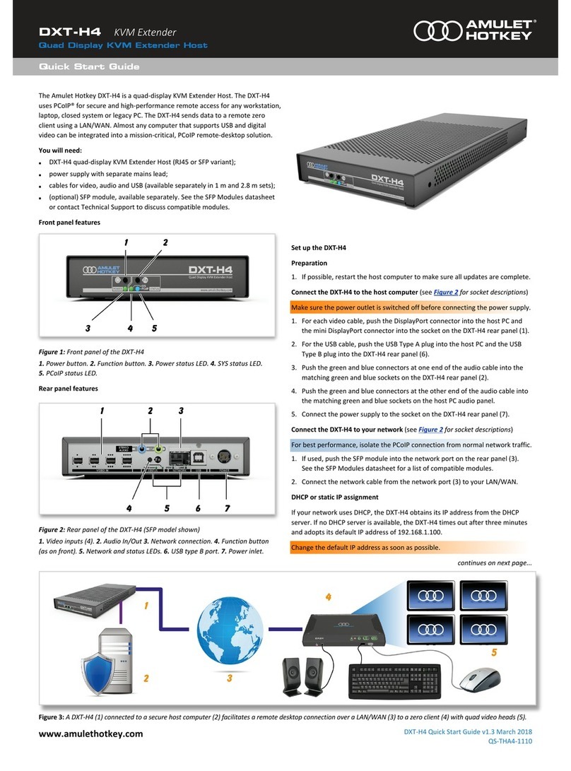
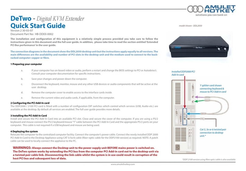
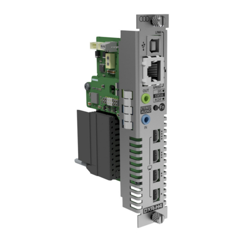
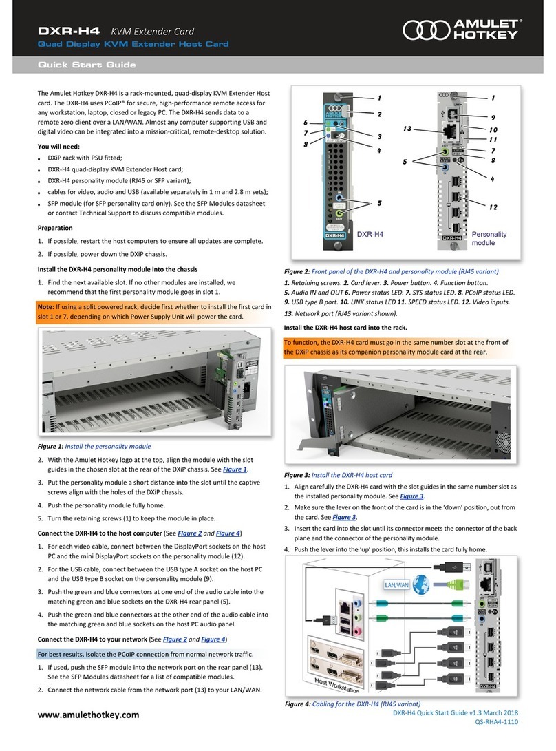
Amulet Hotkey DXR-H4 User manual

®
Quad display KVM ExtEndEr Host Card
User manUal
DXR-H4 and DXR-H4 SFP variant
HB-RHA4-1110
Revision 2.1 November 2020

Product Information
Page 2

CAUTION
To prevent damage to the DXR-H4:
• install in accordance with these instrucons;
• always turn o and unplug the host computer
before handling the unit;
• always use appropriate an-stac handling
procedures when handling the unit;
• only use aachments and accessories
approved by Amulet Hotkey;
• do not expose the unit to moisture;
• do not place objects lled with liquids on or
near the unit;
• clean the unit only with a dry cloth;
• refer all servicing to qualied personnel.
©2020 Amulet Hotkey Ltd. All rights reserved.
The informaon contained in this document represents the current view of Amulet Hotkey® as of the date of publicaon. Because Amulet Hotkey must respond to
changing market condions, it should not be interpreted to be a commitment on the part of Amulet Hotkey, and Amulet Hotkey cannot guarantee the accuracy of any
informaon presented aer the date of publicaon. Secons of this document are reproduced with the kind permission of Teradici®Corp. This document is for informa-
onal purposes only. Amulet Hotkey make no warranes, express, implied or statutory, as to the informaon in this document. Complying with all applicable copyright
laws is the responsibility of the user. Without liming the rights under copyright, no part of this document may be reproduced, stored in or introduced into a retrieval
system, or transmied in any form or by any means (electronic, mechanical, photocopying, recording, or otherwise), or for any purpose, without express wrien per-
mission from Amulet Hotkey. Amulet Hotkey may have patents, patent applicaons, trademarks, copyrights, or other intellectual property rights covering subject maer
in this document. Except as expressly provided in any wrien license agreement from Amulet Hotkey, the furnishing of this document does not give you any license to
these patents, trademarks, copyrights, or other intellectual property. Teradici, PC-over-IP, and PCoIP are registered trademarks of Teradici Corporaon. VMware and View
are registered trademarks of VMware Corp. Amulet Hotkey and ‘soluons you can bank on’ are trademarks of Amulet Hotkey Ltd. The names of actual companies and
products menoned herein may be the trademarks of their respecve owners.
Quad Display KVM Extender Host Card
Thank you
Thank you from everyone at Amulet Hotkey for purchasing this
product. Much me and energy has gone into making this the
best and most reliable soluon available. We are condent we
have provided a state-of-the-art unit that will provide you with
long and reliable service regardless of the applicaon.
To get the best from this product, follow this manual carefully.
Shipment and product inspecon
Your product was carefully packed prior to despatch to
guarantee safe transit. Make sure you thoroughly examine all
packaging and contents for signs of physical damage before use.
If any damage has occurred, nofy the shipping company and
your supplier immediately. Otherwise, claims for damage or
replacement may not be granted.
Retain the original packaging for use in the event that the
equipment has to be stored, shipped or returned for service.
If you choose to dispose of the packaging, please do so in an
environmentally friendly fashion.
Technical support
If you have further quesons , do not hesitate to contact
Amulet Hotkey technical support for expert assistance:
Compliance Noce
See the Legislaon Sheet LS-AHKL-0001 for details of current EU
and FCC compliance.
Cauon: !
This equipment is compliant with Class A of CISPR
32. In a residenal environment this equipment may cause radio
interference.
Cauon: !
The CE/EMC compliance is tested with video, USB and
audio cables that are no longer than 3 m long.
www.amulethotkey.com | Page 3
LASER SAFETY
The DXR-H4 SFP variant may be ed with SFP
network modules that contain Class 1 lasers. The
SFP module emits invisible radiaon which can
cause harm if installed or serviced incorrectly.
Follow the guidelines below:
Warning: Class 1 laser product.
Warning: Invisible laser radiaon can be
emied from the aperture of the SFP port
when no bre is connected. To avoid exposure
to laser radiaon, do not stare into open
apertures.
Warning: Only trained and qualied personnel
may install, replace, or service this equipment.
Product Information
Page 4
ContentsContents
1. Before you start ................................... 9
1.1 Rack mount chassis .................................. 9
1.2 Personality modules ................................ 9
1.3 SFP modules ............................................. 9
1.4 Cabling ..................................................... 9
1.5 USB devices .............................................. 9
1.6 Audio ...................................................... 10
1.6.1 Front and rear audio .......................................10
1.6.2 Connecng to DXZ4 zero client audio .............10
1.7 Cooling ................................................... 10
1.7.1 Blanking plates ...............................................10
1.8 IP and MAC addresses............................ 10
1.9 Other models ......................................... 10
1.10 Terminology ........................................... 10
2. Your DXR-H4 host card at a glance...... 11
2.1 Front panel features............................... 11
2.2 Personality module features .................. 12
2.3 Status LED descripons .......................... 13
2.3.1 Front panel status LEDs .................................. 13
2.3.2 Rear panel status LEDs ...................................13
2.3.3 Key .................................................................. 13
2.3.4 Power LED ...................................................... 13
2.3.5 SYS status LED .................................................14
2.3.6 PCoIP status LED ............................................. 14
2.3.7 SPEED status LED: ........................................... 14
2.3.8 LINK status LED ...............................................14
2.4 Buon operaon .................................... 15
2.4.1 Power ............................................................. 15
2.4.2 Fn ...................................................................15
2.4.3 Enable the Management Interface .................15
2.5 Warning alarm ....................................... 15
3. Set up the DXR-H4.............................. 17
3.1 Turn the power o ................................. 17
3.2 STEP 1: Prepare the PC, workstaon or
servers.................................................... 17
3.2.1 STEP 2: Install the personality module ...........17
3.3 STEP 3: Connect the personality module
to the host computer ............................ 18
3.4 STEP 4: Connect the DXR-H4 to the
network .................................................. 18
3.5 STEP 4: Install the DXR-H4 card into the
rack ........................................................ 19
3.6 STEP 5: Change the default IP address ... 19
3.7 STEP 6: Connect a zero client to the
DXR-H4 ................................................... 20
3.7.1 Connect to a DXR-H4 using SLP Discovery ......20
3.8 STEP 7: Change the default password .... 20
3.9 Setup complete ...................................... 20
3.10 How to power down the DXR-H4 ........... 20
3.11 Further reading ...................................... 20

Quad Display KVM Extender Host Card
www.amulethotkey.com | Page 5
5. Set up a PCoIP session........................ 25
5.1 Power up the zero client ........................ 25
5.2 Types of PCoIP session .......................... 25
5.2.1 Auto Detect ....................................................25
5.2.2 Connect directly to a specied host ..............25
5.2.3 Connect to a choice of hosts using SLP
Discovery ........................................................ 26
5.2.4 PCoIP Connecon Manager ............................26
5.2.5 PCoIP Connecon Manager + Auto-Logon .....26
5.2.6 Connect using VMware View .........................26
5.2.7 Connect with View Connecon Server and
Auto-Logon .....................................................26
5.2.8 Connect using a connecon broker ................27
5.3 Set an automac connecon ................. 27
5.4 Connect to a so client .......................... 28
5.5 Disconnect from a host PC or virtual
desktop .................................................. 28
5.6 Further informaon ............................... 28
4. Introducon to PCoIP......................... 21
4.1 What is PCoIP? ....................................... 21
4.1.1 Host rendering ................................................ 21
4.1.2 Mul-codec display processing ......................22
4.1.3 Dynamically adapts to network condions ....22
4.2 About PCoIP hosts .................................. 22
4.2.1 Host funcon ..................................................22
4.2.2 Host types ....................................................... 22
4.3 About PCoIP zero clients ........................ 22
4.3.1 Funconality ................................................... 22
4.3.2 Data handling .................................................22
4.4 Benets of PCoIP zero clients................. 22
4.4.1 Increased security ..........................................22
4.4.2 Low maintenance ...........................................23
4.4.3 Cost savings .................................................... 23
4.5 PCoIP management tools ....................... 23
4.5.1 PCoIP Management Console ..........................23
4.5.2 Administrave Web Interface (AWI) ...............24
4.5.3 On Screen Display (OSD) .................................24

Contents
Page 6
8. Addional informaon....................... 37
8.1 Fix temporal dithering issues ................. 37
8.1.1 Disable temporal dithering on MACs .............37
8.1.2 Disable temporal dithering on a Windows PC or
Workstaon .................................................... 37
8.2 Localcursor funcon and hotkey
disconnect .............................................. 37
8.2.1 Enable the localcursor funcon ......................37
8.2.2 Disable the localcursor funcon ..................... 37
8.2.3 Use the hotkey disconnect funcon ...............38
8.3 How to review Teradici so client logs on
a PC ........................................................ 38
8.4 How to collect so client logs on an Apple
Mac ........................................................ 38
8.4.1 Display log les with the macOS Console .......38
8.4.2 Display log les with a macOS terminal window
........................................................................38
8.5 How to reset the DXR-H4 at the DXiP rack
............................................................... 38
8.5.1 Factory reset ................................................... 38
8.5.2 Re-enable host driver funcon aer a factory
reset ...............................................................39
8.5.3 Forced reboot ................................................. 39
8.6 How to reset the DXR-H4 remotely........ 39
8.6.1 Restart the DXR-H4 remotely .........................39
8.6.2 Reset the Teradici processor remotely ...........39
8.6.3 Factory reset the DXR-H4 remotely ................40
8.7 How to put the DXR-H4 into standby ..... 40
8.7.1 Put the DXR-H4 into standby locally ............... 40
8.7.2 Put the DXR-H4 into standby remotely ..........40
8.8 How to remove the DXR-H4 from the DXiP
rack ........................................................ 41
8.9 Disable the Management Interface ....... 41
8.10 Addional funconality ......................... 41
9. Technical specicaons ...................... 43
9.10.1 Warranty ......................................................... 43
9.10.2 Technology .....................................................43
9.10.3 Environment ................................................... 44
6. Manage the network ......................... 29
6.1 Dual IP conguraon.............................. 29
6.2 Find the DXR-H4 MAC addresses ........... 29
6.3 Discover the IP addresses ...................... 29
6.3.1 Use the DHCP server to idenfy the IP
addresses ........................................................29
6.3.2 Use DOS command window to idenfy the IP
addresses ........................................................29
6.3.3 Use a TFTP window to idenfy the IP addresses
........................................................................30
6.4 How to change the IP address ............... 30
6.5 Consider network bandwidth
requirements ......................................... 30
6.5.1 Factors aecng bandwidth ...........................30
6.5.2 What happens when available bandwidth is
exceeded ........................................................30
6.6 Choose a connecon broker if required 31
6.6.1 Role of the connecon broker ........................ 31
6.6.2 Specify the connecon broker ........................31
6.6.3 Using the connecon broker ..........................31
7. Firmware updates .............................. 33
7.1 Connect to the correct IP address .......... 33
7.2 Manage the DXR-H4 ............................... 33
7.2.1 Teradici Administrave Web Interface (AWI) .33
7.2.2 Amulet Hotkey Management Interface (MI) .. 33
7.2.3 Enable the connecon to the Management
Interface .........................................................33
7.3 Login to the management interfaces ..... 33
7.3.1 To login with the AWI .....................................33
7.3.2 To login with the Amulet Hotkey Management
Interface .........................................................34
7.4 Check the DXR-H4 rmware .................. 35
7.4.1 Keep rmware up to date ...............................35
7.4.2 Check the Teradici rmware ...........................35
7.4.3 Check the Amulet Hotkey rmware versions . 35
7.5 Update the DXR-H4 rmware ................ 35
7.5.1 Update the Teradici rmware .........................35
7.5.2 Update the Amulet Hotkey rmware ............. 35

Quad Display KVM Extender Host Card
www.amulethotkey.com | Page 7
List of guresList of gures
Figure 1:Front panel features�������������������������������������������������������������������������������������������������������������������������� �11
Figure 2:Rear panel features (RJ45 model) ����������������������������������������������������������������������������������������������������� �12
Figure 3:Status LEDs on the front panel���������������������������������������������������������������������������������������������������������� �13
Figure 4:Status LEDs on the rear panel (SFP model shown) �����������������������������������������������������������������������������13
Figure 5:Install the personality module����������������������������������������������������������������������������������������������������������� �17
Figure 6:Cabling for the DXR-H4 (RJ45 variant shown) ����������������������������������������������������������������������������������� �18
Figure 7:Example SFP modules������������������������������������������������������������������������������������������������������������������������ �18
Figure 8:Install the DXR-H4 host card ������������������������������������������������������������������������������������������������������������� �19
Figure 9:�����������������������
Figure 10:Typical PCoIP set up ����������������������������������������������������������������������������������������������������������������������� �21
Figure 11:PCoIP Management Console home page ���������������������������������������������������������������������������������������� �23
Figure 12: �������������������������������������������������������������������������������������������������������� �24
Figure 13:OSD Connect screen ������������������������������������������������������������������������������������������������������������������������ �24
Figure 14:�������������������������������������������������������������������������������������������������������25
Figure 15:���������������������������������������������������������������������������������������������������������25
Figure 16:���������������������26
Figure 17: ����������������������������������������������������������������������������������������������������26
Figure 18: ����������������������������������������������������������������������������������27
Figure 19: �������������������������������������������������������������������������������������������������� �27
Figure 20:����������������������������������������������������������������������������������������������������������28
Figure 21:�������������������������������������������������������������������������������������������������������� �29
Figure 22: �����������������������������������������������������������������������������������29
Figure 23: ��������������������������������������������������������������������������������������������������������� �33
Figure 24: ���������������������������������������������������������������������������������������������������������������������������� �34

Contents
Page 8
List of tablesList of tables
Table 1:�������������������������������������������������������������������������������������13
Table 2: ��������������������������������������������������������������������������������������������13
Table 3: ����������������������������������������������������������������������������������������������������������������14
Table 4: ���������������������������������������������������������������������������������������������������14
Table 5:�������������������������������������������������������������������������������������������������������������14
Table 6: �����������������������������������������������������������������������������������������������14
Table 7: ��������������������������������������������������������������������������������������������������������������� �14
Table 8: ������������������������������������������������������������������������������������������������������������������ �14
Table 9: ����������������������������������������������������������������������������������������������������������������������
Table 10:Zero client management tools�����������������������������������������������������������������������������������������������������������23
Table 11:PCoIP bandwidth requirements��������������������������������������������������������������������������������������������������������
Table 12: ����������������������������������������������������������������������������������43
Table 13:�������������������������������������������������������������������������������������������������������������44
Figure 25:SSH client �����������������������������������������������������������������������������������������������������������������������������������������34
Figure 26:Management interface login �����������������������������������������������������������������������������������������������������������34
Figure 27:Management Interface screen ���������������������������������������������������������������������������������������������������������34
Figure 28: ��������������������������������������������������������������������������35
Figure 29:Firmware Upload window��������������������������������������������������������������������������������������������������������������� �35
Figure 30:Successful upload window ���������������������������������������������������������������������������������������������������������������35
Figure 31:Insert jumper into the reset port������������������������������������������������������������������������������������������������������38
Figure 32: �������������������������������������������������������������������������������������������������������������39
Figure 33:The Reset screen ������������������������������������������������������������������������������������������������������������������������������39

www.amulethotkey.com | Page 9
BEforE you start 1
1. Before you start
This manual is for the Amulet Hotkey DXR-H4 Quad Display KVM
Extender Host Card.
The Amulet Hotkey DXR-H4 is based on KVM-over-IP technology
using the industry standard PCoIP® protocol. It is an ideal host
soluon for remote desktop applicaons that require pixel
perfect video across mulple monitors.
Before you connect a host card to a PCoIP system, be aware of
the following informaon.
1.1 Rack mount chassis
The DXR-H4 Quad-Display KVM Extender Host Card is rack-
mounted in a specialised housing that takes the host card in the
front of the chassis and an associated personality module (see
1.2) in the rear of the chassis.
The chassis can hold a maximum of 12 DXR-H4 host cards and 12
personality modules.
The rack comes in two conguraons:
• standard: each Power Supply Unit (PSU) powers all slots (1
to 12), this gives the rack dual redundancy for the PSUs.
• split: PSU A supplies slots 1 to 6 and PSU B supplies slots
7 to 12. This is a security opon where any card can only
be fed from a single AC outlet and PSU. There is no dual
redundancy (contact Amulet Hotkey for split rack details)
1.2 Personality modules
The DXR-H4 has an accompanying personality module that ts
into the rear of the chassis. The personality module is available
in two versions:
RJ45: The standard personality module has a single RJ45
network port;
SFP: The personality module is also available with a single
network port that accepts either a ber or copper SFP module
(see 1.3 and Figure 2).
1.3 SFP modules
Amulet Hotkey can provide a range of suitable SFP modules;
including 1 Gbps and 100 Mbps ber SFP modules for single
or mul-mode ber, and copper SFP modules with RJ45
connectors. See the Amulet Hotkey SFP Modules Datasheet for
details of currently available modules.
Be aware that SFP modules have diering specicaons and that
the distances over which they can drive a signal can vary. This
especially applies to ber SFP modules.
Important!
The SFP variant only supports certain models of
SFP module. If in doubt, contact Technical Support for advice.
1.4 Cabling
You will need the following cables, available separately in short
(1 m) and long (2.8 m to 3 m) sets:
• video cable (for example Mini DisplayPort to DisplayPort);
• two stereo audio cables;
• USB cable (type A to type B).
Note: The Amulet Hotkey audio cables comprise two cables
each with a blue connector at one end and a green connector
at the other. The instrucons in this manual are specic for
this parcular cable set.
Cauon: !
The CE/EMC compliance is tested with video, USB and
audio cables with a maximum length of 3 m.
1.5 USB devices
The DXR-H4 supports a broad range of Human Interface (HID)
USB devices such as keyboards, mice and graphics tablets. There
is also planned support soon for bulk transfer USB devices such
as card readers and USB memory scks.
See the latest release notes for KVM Extender Switches on the
resources product page for details of what is supported.
Cauon: !
Isochronous devices such as web cams and USB audio
devices are not supported and will not work via remong.

Before you start
Page 10
1.8 IP and MAC addresses
Before you set up a host, make a note of these details:
• MAC and IP address of the PCoIP host;
• MAC and IP address of the zero client.
You will nd the MAC address informaon wrien on the
underside of the zero client and on the conguraon record/
serial number label of the host. You can also use the AWI (see
4.5.2) to nd the MAC addresses.
If your network uses DHCP, the host and zero client obtain
their IP addresses from the DHCP server. If no DHCP server is
available, the host and zero client me out aer approximately
three minutes and adopt the following default IP addresses:
• Zero client: 192.168.1.50;
• PCoIP Host: 192.168.1.100.
1.9 Other models
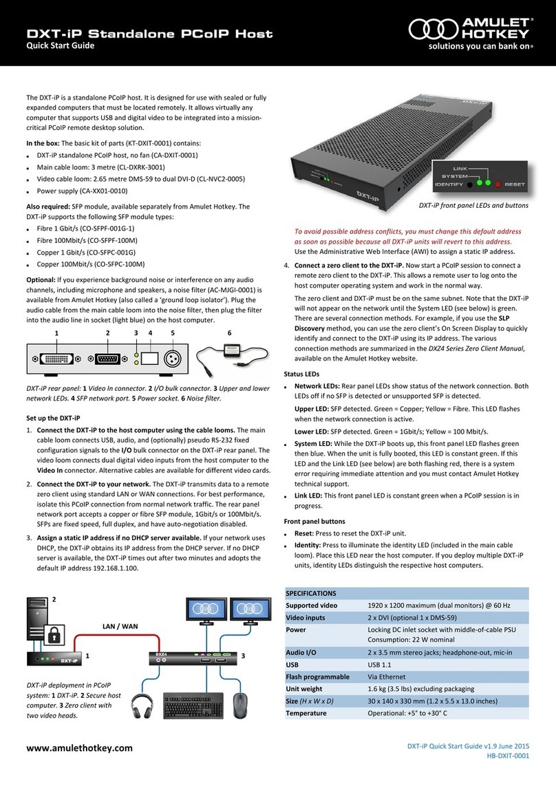
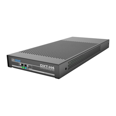
A ‘stand alone’ variant of this product, the DXT-H4 Quad Display
KVM Extender Host is also available. The DXT-H4 combines both
the card and personality module in a single enclosure and comes
with its own power supply.
1.10 Terminology
The general terms ‘KVM Extender’, ‘PCoIP host’ or ‘host’ are
used throughout this manual to describe all product variants.
1.6 Audio
1.6.1 Front and rear audio
On the DXR-H4, only the front or rear audio connecons can
be acve at one me. The rear connecons take precedence (if
there are connectors in both, or in neither).
Which port is acve depends on what port has connectors
plugged in at switch-on.
Cauon: !
Changing the connecon from front to rear or rear to
front while the unit is on will not change where the audio output
is coming from unl the unit is reset.
1.6.2 Connecng to DXZ4 zero client audio
Only connect a DXZ4 to the DXR-H4 using the phones out
socket on the DXZ4. The LINE OUT port has no funcon when
connecng to a DXR-H4.
1.7 Cooling
The unit is fan cooled. To ensure opmum venlaon and
performance of the unit, observe the following:
1. Make sure blanking plates are ed in all unused card slots.
2. Make sure there is a 1U space above and below the DXiP
rack.
For more informaon see the user
manual.
1.7.1 Blanking plates
The DXiP rack typically comes ed with blanking plates into all
unused slots at the front and back of the chassis. It is important
for EMC compliance and for cooling to make sure that these are
all ed. All slots must have either:
• a DXR-H4 host card;
• personality module;
• or blanking plate ed.

www.amulethotkey.com | Page 11
your dxr-H4
2. Your DXR-H4 host card at a glance
The DXR-H4 is a KVM Extender Host Card based on KVM-over-IP
technology, using the industry standard PCoIP® protocol. Each
host card supports up to four heads of video at the desktop and
partners with a person ality module for connecvity and network
opons.
DXR-H4 host cards have ports, buons and LEDs on the front
and rear panels. This secon gives you informaon to idenfy
the cards and their features.
The cards also have a useful feature to make it easy to cross
reference the front and rear panel. The DXR-H4 host card and
the personality module have a funcon to help idenfy the card
by ashing the front and rear panel ID LEDs simultaneously. This
is useful when connecng cables to the cards.
2.1 Front panel features
The front panel on the DXR-H4 has three LEDs and two buons.
See Figure 1 for the following descripon:
1. Retaining screw: Two screws, one at the top and one at the
boom hold the card in place.
2. Card lever: For removing the card easily from the rack.
3. Power buon: Takes the unit in and out of standby. Can also
reset the unit. See 8.7 and 8.5.3.
4. Funcon buon: Turns the ID mode on and o. Can also
enable the management interface. See 2.4.
5. Audio: Stereo microphone and audio sockets.
6. Power status LED: Displays the power state of the unit. See
2.3 for full LED descripons.
7. SYS status LED: In normal operaon, this LED shows network
acvity and connecon type. See 2.3 for LED descripons.
8. PCoIP status LED: Shows the PCoIP network status. See 2.3
for full LED descripons.
2
Figure 1: Front panel features

Your DXR-H4
Page 12
2.2 Personality module features
The panel on the DXR-H4 personality module has sockets, status
LEDs and a funcon buon.
See Figure 2 for the following descripon:
1. Retaining screw: Two screws, one at the top and one at the
boom hold the card in place.
2. USB port: A USB type B socket for USB trac to and from the
host workstaon or PC.
3. Network connecon: There are two models of the person-
ality module available with either an RJ45 or SFP network
socket. The SFP variant accepts a range of copper and ber
modules.
4. Network LEDs: SPEED and LINK network status LEDs. See 2.3
for full LED descripons.
5. Status LEDs: SYS and PCoIP status LEDs. See 2.3 for full LED
descripons.
6. Audio In/Out: There are two stereo 3.5 mm sockets, one
green and one blue, to connect the audio microphone and
speaker signals from the host workstaon or PC. These are
duplicated from the front panel.
7. Funcon buon: Same funcon as the buon on the front
panel. Turns the ID mode on and o. Can also enable the
management interface.
8. Video inputs: There are four video inputs to connect up to
four video sources with Mini DisplayPort connecons.
Figure 2: Rear panel features (RJ45 model)

Quad Display KVM Extender Host Card
www.amulethotkey.com | Page 13
2.3 Status LED descripons
The status LEDs on the front and rear panels show the status of
the unit and network connecon including:
• the connecon type and speed;
• the current network acvity;
• the status of the PCoIP connecon to a client;
• fault indicaons, power and standby status.
2.3.1 Front panel status LEDs
There are three LEDs on the front panel (see Figure 3):
• Power LED, see 2.3.4;
• SYS status LED, see 2.3.5;
• PCoIP status LED, see 2.3.6.
Figure 3: Status LEDs on the front panel
2.3.2 Rear panel status LEDs
There are four LEDs on the rear panel (see Figure 4):
• PCoIP status LED, see 2.3.6;
• SYS status LED, see 2.3.5;
• SPEED status LED, see 2.3.7;
• and the LINK status LED, see 2.3.8.
Figure 4: Status LEDs on the rear panel (SFP model shown)
2.3.3 Key
The tables in this secon use the following convenons:
• Color - LED is on steady;
• Flash - LED is on and o evenly;
• Blink - LED is on more than o;
• Wink - LED is o more than on.
2.3.4 Power LED
Tells you the power status of the DXR-H4.
1. Standard DXiP rack (see 1.1 on page 9).
When viewed from the front:
LED status Meaning
Blue Unit is powered by both PSUs
Magenta
DXR-H4 card is powered by PSU on le
(PSU on right has failed, is missing or card
internal protecon fuse is open)
Amber
DXR-H4 card is powered by PSU on right
(PSU on le has failed, is missing or card
internal protecon fuse is open)
Table 1:
2. Split DXiP rack (see 1.1 on page 9).
When viewed from the front:
LED status Meaning
Red DXR-H4 card is powered by PSU on le
Green DXR-H4 card is powered by PSU on right
Table 2:

Your DXR-H4
Page 14
2.3.6 PCoIP status LED
Displays the status of the PCoIP session.
1. When the card is in STANDBY:
LED status Meaning
O Unit is in standby
Table 5:
2. When the card is in ON:
LED status Meaning
Green ash
Synchronized with Teradici processor
‘heartbeat’. Processor is ready but not in an
acve session
Green Unit is in an acve PCoIP session
Red Teradici processor boot fault
Table 6:
2.3.7 SPEED status LED:
Displays the speed of the network connecon.
Status Meaning
O No network connecon
Amber 100 Mbit/s connecon
Green 1 Gbit/s connecon
Table 7:
2.3.8 LINK status LED
Displays the status of the network connecon.
1. LINK status LED
Status Meaning
O No network connecon
Green Network connecon; no trac
Green blink Network connecon full duplex; trac
detected
Amber blink Network connecon half duplex; trac
detected (PCoIP not working)
Table 8:
2.3.5 SYS status LED
Tells you the state of the system and the network link.
1. When the unit is in STANDBY:
LED status Meaning
Red Unit is in standby, no wake mode enabled
Amber Unit is in standby with Wake-on-LAN enabled
Amber ash
Amber/Blue ash
Unit is starng up
Table 3:
2. When the unit is ON:
LED status Meaning
Amber wink Unit is powering down
Amber/Red ash Unit has a fault. Contact Technical Support
Green ash Copper network connecon is detected (SFP
module or RJ45). No network link is established
Green Copper network connecon with link
established (SFP module or RJ45)
Cyan ash (fast) Fn buon press is enabling the network
Red/O/Green/
O/Blue/O
ash
Unit is in ID mode (this mode overrides all other
indicaons)
Color cycle Red/
Amber/Green/
Cyan/Blue/
Magenta/Pink
Unit is in programming mode
Red ash Unit has a fault. Contact Technical Support
For SFP Modules only:
Cyan ash (slow) No SFP module inserted
Blue ash SFP ber module detected; no network
connecon
Blue SFP ber module detected; connected to
network
Table 4:

Quad Display KVM Extender Host Card
www.amulethotkey.com | Page 15
2.4 Buon operaon
There are two buons on the front of the unit, the Power
buon and the Fn buon. The Fn buon is also repeated on the
personality module at the rear of the chassis.
2.4.1 Power
a). Press the buon to put the DXR-H4 in or out of standby.
b). A long press (more than four seconds) at any me will
reset the DXR-H4.
2.4.2 Fn
a). A long press (more than four seconds) of the front or rear
Fn buon puts the SYS LEDs into ID mode.
b). Press the front Fn buon on the unit during power up
or the reset cycle to enable the Management Interface
connecon. See 2.4.3.
2.4.3 Enable the Management Interface
In order to access the COM module for acvies such as
rmware updates, or when using a connecon broker, it is
necessary to enable the Management Interface (MI).
To do this using the buons on the unit:
When the unit is powered on:
1. Press and hold both the Fn and Power buons.
The LEDs turn o briey then ash ORANGE.
2. Release the Fn and Power buons at the same me.
3. Wait to hear an audible beep.
An audible beep indicates that the operaon is successful.
When the unit is powered o:
1. Press and hold the Fn buon.
2. Press the Power buon briey and release both buons at
the same me.
Note: To enable the MI permanently, you can do this with a
command from the MI command window. See Enable the
connecon to the Management Interface (on page 33).
2.5 Warning alarm
Under certain condions, such as failure of an internal power
rail on the DXR-H4 card, a warning buzzer may sound to indicate
that there is a problem, even though the card will aempt to
maintain the PCoIP link if this is possible.
The alarm can be paused by placing the card with the alarm
into ID mode (see 2.4.2). If the alarm condion persists when
the card is taken out of ID mode, the alarm will sound again. Do
not connue to use the card, invesgate the cause of the alarm.
Contact Amulet Hotkey Technical Support for assistance.

Your DXR-H4
Page 16

www.amulethotkey.com | Page 17
install tHE dxr-H4
3. Set up the DXR-H4.
This secon describes how to set up the DXR-H4.
For a descripon of the unit, see 2. Your DXR-H4 host card at a
glance.
The installaon requires that a DXiP chassis is already installed.
For informaon on how to do this, see the DXiP Quick Start
Guide, QS-DXIP-0001.
Note: This procedure outlines the install process for a single
host PC and DXR-H4 card and personality module. You can
repeat this process to install addional cards.
3.1 Turn the power o
Although the cards can be inserted whether the PSUs are
powered on or o, we recommend that where possible you
power the rack down before installing new cards.
3.2 STEP 1: Prepare the PC, workstaon or servers
Cauon: !
Switch-o the host PC before you install the DXR-H4.
1. If possible, restart the host computers to make sure any
previous updates are successfully completed.
3
3.2.1 STEP 2: Install the personality module
Important!
If using a split powered rack, decide rst whether
to install the rst card in slot 1 or 7, depending on which
Power Supply Unit will power the card.
1. Find the next available slot in the DXiP chassis. If no other
modules are installed, we recommend that the rst personality
module goes in slot 1.
2. With the Amulet Hotkey logo at the top, align the module
with the slot guides in the chosen slot at the rear of the DXiP
chassis. See Figure 5.
3. Put the personality module a short distance into the slot unl
the capve screws align with the holes of the DXiP chassis.
4. Push the personality module fully home.
5. Turn the retaining screws to keep the module in place.
Figure 5: Install the personality module

Install the DXR-H4
Page 18
3.3 STEP 3: Connect the personality module to the
host computer
Cauon: !
CE/EMC compliance is tested with video, USB and
audio cables with a maximum length of 3m.
Refer to Figure 6 for the following connecons:
1. For each video cable, connect between the DisplayPort
sockets on the host PC and the Mini DisplayPort sockets on the
personality module.
2. For the USB cable, push the USB type A plug into the host PC
and the USB type B plug into the personality module.
3. Connect the audio cables:
a). If using the Amulet Hotkey audio loom, push the green
and blue connectors at one end of the audio loom into
the matching green and blue sockets on the DXR-H4 rear
panel.
b). If using the Amulet Hotkey audio loom, push the green
and blue connectors at the other end of the audio loom
into the matching green and blue sockets on the PC audio
panel.
4. Turn the host computer ON.
3.4 STEP 4: Connect the DXR-H4 to the network
Cauon: !
For the best performance, isolate the PCoIP
connecon from normal network trac.
1. For the DXR-H4 SFP variant only, push the SFP module (see
Figure 7) into the network port on the personality module (see
(3) in Figure 2).
Note This socket accepts a copper or bre SFP module. The
module can be 1 Gbit/s or 100 Mbit/s. See the SFP modules
datasheet for more details of available modules.
Figure 7: Example SFP modules
2. Connect the network cable from the network port to your
LAN/WAN.
Figure 6: Cabling for the DXR-H4 (RJ45 variant shown)

Quad Display KVM Extender Host Card
www.amulethotkey.com | Page 19
3.5 STEP 4: Install the DXR-H4 card into the rack
Cauon: !
To funcon, the DXR-H4 card must go in the same
number slot at the front of the DXiP chassis as its companion
personality module card at the rear.
1. Align carefully the DXR-H4 card with the slot guides in the
same number slot as the installed personality module. See
Figure 8.
2. Make sure the lever on the front of the card is in the ‘down’
posion, out from the card. See Figure 8.
3. Insert the card into the slot unl its connector meets the
connector of the back plane and the connector of the person-
ality module.
4. Push the lever into the ‘up’ posion, this installs the card
fully home.
5. If the DXiP rack has been powered down, turn the power to
the rack back on.
Note: If you will install more cards into the rack, wait unl all
cards are installed before you turn the power back on.
3.6 STEP 5: Change the default IP address
Cauon: !
Change the default IP address as soon as possible.
If your network uses DHCP, the DXR-H4 obtains its IP address
from the DHCP server. If no DHCP server is available, the DXR-H4
mes out aer three minutes and adopts its default IP address
of 192.168.1.100.
All DXR-H4 cards will revert to the same default IP address, this
can cause conicts as the network grows. Use the Administrave
Web Interface (AWI) to assign a dierent stac IP address from
the default.
1. Enter the default IP address of the DXR-H4 into a browser
to access the AWI. See 7.3.1 To login with the AWI for more
informaon.
2. Enter the default password ahkdante and click Log In.
3. From the Conguraon menu select the Network opon.
4. Make sure the Enable DHCP opon is unchecked.
5. Enter the new fall-back default IP address into the IP Address
elds.
6. Make sure the Enable DHCP opon is checked.
Note: If the IP address has already been changed from the
default, you can discover the IP address using the methods in
6.3 Discover the IP addresses on page 29.
Figure 8: Install the DXR-H4 host card

Install the DXR-H4
Page 20
3.7 STEP 6: Connect a zero client to the DXR-H4
1. Install and power up a zero client.
If you are not sure how to do this, see the relevant Amulet
Hotkey user manual or Quick Start Guide for the zero client.
When the zero client is on, you are ready to establish a new
PCoIP session.
The zero client connects to the DXR-H4 via its network
connecon.
Note: We recommend reading 4. Introducon to PCoIP rst if
you are not already familiar with the concept of PCoIP.
3.7.1 Connect to a DXR-H4 using SLP Discovery
Important!
This is one method you can use to quickly
connect your zero client to a host. For a detailed descripon
of all connecon methods, see 5. Set up a PCoIP session.
If the zero clients and KVM extender hosts are on the same
subnet, you can use the Direct to Host + SLP session connecon
type to discover available PCoIP hosts on the subnet.
You must know the IP address (or MAC address) of the KVM
extender host that you want to connect to.
1. Select the Direct to Host + SLP Host Discovery session
connecon type from the drop down list.
Figure 9:
available PCoIP hosts discovered
2. Select the host you want and click OK.
If the zero client successfully connects to the host, the front
panel PCoIP status LED illuminates green to indicate an acve
session.
3. (Oponal) You can also set the Enable Auto-Reconnect in the
advanced sengs to remember the last connected PCoIP host.
Note: You must also congure a Direct from Client session
connecon type on the host.
3.8 STEP 7: Change the default password
1. For security, we recommend that you change the default
password for your DXR-H4 at the earliest possibility.
2. See 7.3 Login to the management interfaces on page 33
for how to access the management pages where you can change
the password.
Important!
You must enter a password before changing
the conguraon of host cards and zero clients. The factory
pre-set password for all Amulet Hotkey host cards and zero
clients is ahkdante.
3.9 Setup complete
Once the zero client successfully connects to the host, check for
the following indicaons to show normal operaon:
LED Status Descripon
Power GREEN Card is ON
SYS GREEN Copper network
connecon
SYS BLUE Fiber network
connecon
PCoIP GREEN / GREEN
ash Teradici processor OK
LINK GREEN / GREEN
ash
Network trac
indicaon
SPEED
GREEN
AMBER
1 Gbit network
available
100 Mbit network
available
Table 9:
Note: The LEDs do not indicate whether the status of the MI is
enabled or disabled. See 7.3.
3.10 How to power down the DXR-H4
To correctly shut down the unit, you must put the DXR-H4 into
standby:
• before you remove it from the DXiP rack, or;
• before you remove power to the rack.
See 8.8 for more details.
3.11 Further reading
If you wish to read further about network consideraons, refer
to 6. Manage the network.
For any conguraon or deployment issues such as temporal
dithering, refer to 7. Firmware updates or contact Technical
Support department (see contact details at the start of this
manual).
Other manuals for DXR-H4
2
This manual suits for next models
1
Table of contents
Other Amulet Hotkey Extender manuals

Amulet Hotkey
Amulet Hotkey DXT-iP User manual

Amulet Hotkey
Amulet Hotkey DXZC User manual

Amulet Hotkey
Amulet Hotkey DXT-H4 User manual

Amulet Hotkey
Amulet Hotkey DXT-H4 User manual

Amulet Hotkey
Amulet Hotkey DXT-H4 User manual

Amulet Hotkey
Amulet Hotkey DXR-H4 User manual

Amulet Hotkey
Amulet Hotkey DeTwo User manual

Amulet Hotkey
Amulet Hotkey CoreModule FX600 User manual

Amulet Hotkey
Amulet Hotkey DXR-H4 User manual