solutions you can bank on
®
®
www.amulethotkey.com
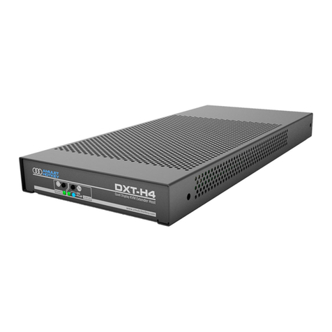
DXT-iP Standalone PCoIP Host
Quick Start Guide
DXT-iP Quick Start Guide v1.9 June 2015
HB-DXIT-0001
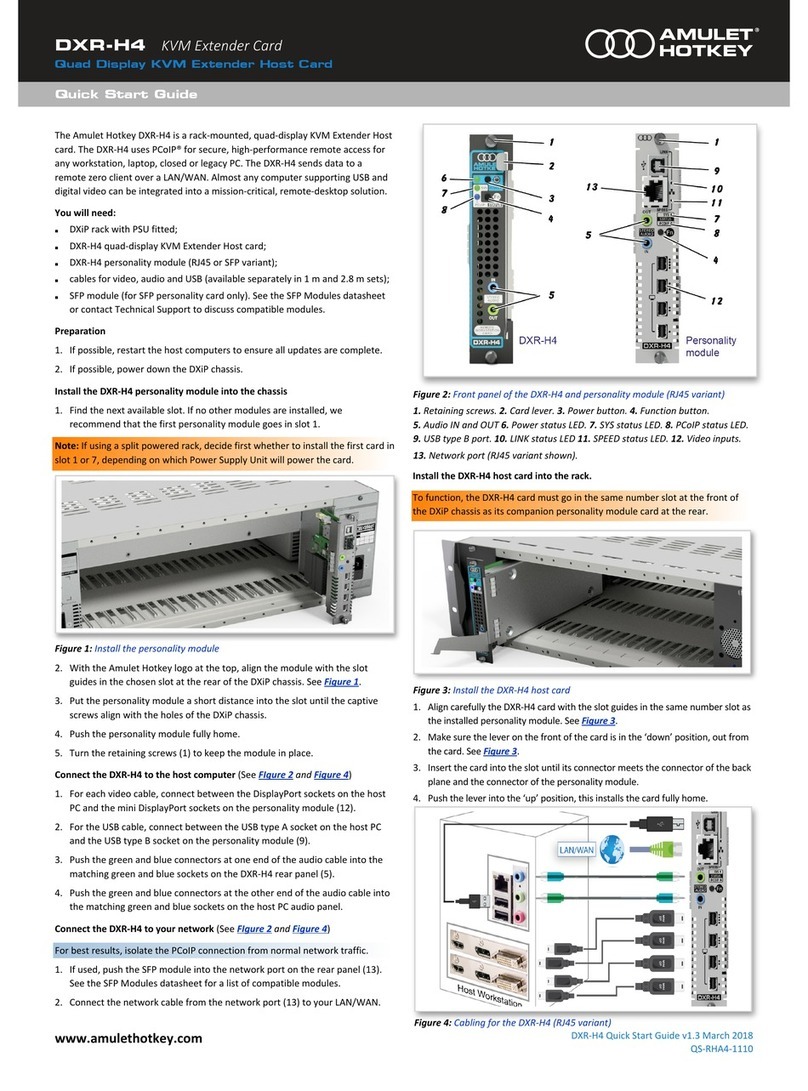
The DXT-iP is a standalone PCoIP host. It is designed for use with sealed or fully
expanded computers that must be located remotely. It allows virtually any
computer that supports USB and digital video to be integrated into a mission-
critical PCoIP remote desktop solution.
In the box: The basic kit of parts (KT-DXIT-0001) contains:
■DXT-iP standalone PCoIP host, no fan (CA-DXIT-0001)
■Main cable loom: 3 metre (CL-DXRK-3001)
■Video cable loom: 2.65 metre DMS-59 to dual DVI-D (CL-NVC2-0005)
■Power supply (CA-XX01-0010)
Also required: SFP module, available separately from Amulet Hotkey. The
DXT-iP supports the following SFP module types:
■Fibre 1 Gbit/s (CO-SFPF-001G-1)
■Fibre 100Mbit/s (CO-SFPF-100M)
■Copper 1 Gbit/s (CO-SFPC-001G)
■Copper 100Mbit/s (CO-SFPC-100M)
Optional: If you experience background noise or interference on any audio
channels, including microphone and speakers, a noise filter (AC-MJGI-0001) is
available from Amulet Hotkey (also called a ‘ground loop isolator’). Plug the
audio cable from the main cable loom into the noise filter, then plug the filter
into the audio line in socket (light blue) on the host computer.
To avoid possible address conflicts, you must change this default address
as soon as possible because all DXT-iP units will revert to this address.
Use the Administrative Web Interface (AWI) to assign a static IP address.
4. Connect a zero client to the DXT-iP. Now start a PCoIP session to connect a
remote zero client to the DXT-iP. This allows a remote user to log onto the
host computer operating system and work in the normal way.
The zero client and DXT-iP must be on the same subnet. Note that the DXT-iP
will not appear on the network until the System LED (see below) is green.
There are several connection methods. For example, if you use the SLP
Discovery method, you can use the zero client’s On Screen Display to quickly
identify and connect to the DXT-iP using its IP address. The various
connection methods are summarized in the DXZ4 Series Zero Client Manual,
available on the Amulet Hotkey website.
Status LEDs
■Network LEDs: Rear panel LEDs show status of the network connection. Both
LEDs off if no SFP is detected or unsupported SFP is detected.
Upper LED: SFP detected. Green = Copper; Yellow = Fibre. This LED flashes
when the network connection is active.
Lower LED: SFP detected. Green = 1Gbit/s; Yellow = 100 Mbit/s.
■System LED: While the DXT-iP boots up, this front panel LED flashes green
then blue. When the unit is fully booted, this LED is constant green. If this
LED and the Link LED (see below) are both flashing red, there is a system
error requiring immediate attention and you must contact Amulet Hotkey
technical support.
■Link LED: This front panel LED is constant green when a PCoIP session is in
progress.
Front panel buttons
■Reset: Press to reset the DXT-iP unit.
■Identity: Press to illuminate the identity LED (included in the main cable
loom). Place this LED near the host computer. If you deploy multiple DXT-iP
units, identity LEDs distinguish the respective host computers.
DXT-iP front panel LEDs and buttons
Set up the DXT-iP
1. Connect the DXT-iP to the host computer using the cable looms. The main
cable loom connects USB, audio, and (optionally) pseudo RS-232 fixed
configuration signals to the I/O bulk connector on the DXT-iP rear panel. The
video loom connects dual digital video inputs from the host computer to the
Video In connector. Alternative cables are available for different video cards.
2. Connect the DXT-iP to your network. The DXT-iP transmits data to a remote
zero client using standard LAN or WAN connections. For best performance,
isolate this PCoIP connection from normal network traffic. The rear panel
network port accepts a copper or fibre SFP module, 1Gbit/s or 100Mbit/s.
SFPs are fixed speed, full duplex, and have auto-negotiation disabled.
3. Assign a static IP address if no DHCP server available. If your network uses
DHCP, the DXT-iP obtains its IP address from the DHCP server. If no DHCP
server is available, the DXT-iP times out after two minutes and adopts the
default IP address 192.168.1.100.
SPECIFICATIONS
Supported video 1920 x 1200 maximum (dual monitors) @ 60 Hz
Video inputs 2 x DVI (optional 1 x DMS-59)
Power Locking DC inlet socket with middle-of-cable PSU
Consumption: 22 W nominal
Audio I/O 2 x 3.5 mm stereo jacks; headphone-out, mic-in
USB USB 1.1
Flash programmable Via Ethernet
Unit weight 1.6 kg (3.5 lbs) excluding packaging
Size (H x W x D) 30 x 140 x 330 mm (1.2 x 5.5 x 13.0 inches)
Temperature Operational: +5° to +30° C
DXT-iP rear panel: 1 Video In connector. 2I/O bulk connector. 3 Upper and lower
network LEDs. 4 SFP network port. 5Power socket. 6Noise filter.
1
1
2
3
DXT-iP deployment in PCoIP
system: 1 DXT-iP. 2Secure host
computer. 3 Zero client with
two video heads.
