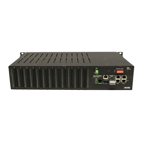
AMX AutoPatch Epica-128 User manual

Epica-128 & Epica-256
qESD Warning
qSafety Information & Notices
qWelcome
qInstruction Manual
qBoards & Specifications
qBCS Serial Control Protocol
June 2007


ESD Warning
To avoid ESD (Electrostatic Discharge) damage to sensitive components, make
sure you are properly grounded before touching any internal materials.
When working with any equipment manufactured with electronic devices,
proper ESD grounding procedures must be followed to ensure people, products,
and tools are as free of static charges as possible. Grounding straps, conductive
smocks, and conductive work mats are specifically designed for this purpose.
Anyone performing field maintenance on AMX AutoPatch equipment should use
an appropriate ESD field service kit, complete with at least a dissipative work
mat with a ground cord and a UL listed adjustable wrist strap with another
ground cord. These items should not be manufactured locally, since they are
generally composed of highly resistive conductive materials to safely drain static
charges, without increasing an electrocution risk in the event of an accident. ESD
protective equipment can be obtained from 3M™, Desco®, Richmond
Technology®, Plastic Systems®, and other such vendors.
Epica-128 & Epica-256 Instruction Manual Introduction i

Important Safety Information
and Instructions
When using and installing your AMX AutoPatch product, adhere to the following basic safety
precautions. For more information about operating, installing, or servicing your AMX AutoPatch
product, see your product documentation.
äRead and understand all instructions before using and installing AMX AutoPatch products.
äUse the correct voltage range for your AMX AutoPatch product.
äThere are no user serviceable parts inside an AMX AutoPatch product; service should only be
done by qualified personnel.
äIf you see smoke or smell a strange odor coming from your AMX AutoPatch product, turn it
off immediately and call technical support.
äFor products with multiple power supplies in each unit, make sure all power supplies are
turned on simultaneously.
äUse surge protectors and/or AC line conditioners when powering AMX AutoPatch products.
äOnly use a fuse(s) with the correct fuse rating in your enclosure.
äMake sure the power outlet is close to the product and easily accessible.
äMake sure the product is on or attached to a stable surface.
äTurn off equipment before linking pieces together, unless otherwise specified in that
product’s documentation.
äFor safety and signal integrity, use a grounded external power source and a grounded power
connector.
äTurn off and unplug an enclosure before adding or removing boards, unless otherwise
specified in that product’s documentation.
äTo avoid shock or potential ESD (Electrostatic Discharge) damage to equipment, make sure
you are properly grounded before touching components inside an AMX AutoPatch product.
Epica-128 & Epica-256 Instruction Manual Introduction ii
Safety

Information et directives
de sécurité importantes
Veuillez vous conformer aux directives de sécurité ci-dessous lorsque vous installez et utilisez
votre appareil AMX AutoPatch. Pour de plus amples renseignements au sujet de l’installation, du
fonctionnement ou de la réparation de votre appareil AMX AutoPatch, veuillez consulter la
documentation accompagnant l’appareil.
äLisez attentivement toutes les directives avant d’installer et d’utiliser les appareils AMX
AutoPatch.
äLe voltage doit être approprié à l’appareil AMX AutoPatch.
äLes appareils AMX AutoPatch ne contiennent aucune pièce réparable par l’usager; la
réparation ne doit être effectuée que par du personnel qualifié.
äSi de la fumée ou une odeur étrange se dégagent d’un appareil AMX AutoPatch, fermez-le
immédiatement et appelez le Service de soutien technique.
äVeillez à ce que tous les blocs d’alimentation des appareils dotés de blocs d’alimentation
multiples dans chaque unité soient allumés simultanément.
äServez-vous de protecteurs de surtension ou de conditionneurs de lignes à courant alternatif
lorsque vous mettez les appareils AMX AutoPatch sous tension.
äPlacez uniquement des fusibles de calibre exact dans les boîtiers.
äVeillez à ce que la prise de courant soit proche de l’appareil et facile d’accès.
äVeillez à ce que votre appareil AMX AutoPatch soit installé sur une surface stable ou qu’il y
soit fermement maintenu.
äFermez toutes les composantes de l’équipement avant de relier des pièces, à moins
d’indication contraire fournie dans la documentation de l’appareil.
äPar mesure de sécurité et pour la qualité des signaux, servez-vous d’une source d’alimentation
externe mise à la terre et d’un connect d’alimentation mis à la terre.
äFermez et débranchez le boîtier avant d’ajouter ou d’enlever des plaquettes, à moins
d’indication contraire fournie dans la documentation du appareil.
äPour éviter les chocs ou les dommages éventuels causés à l’équipement par une décharge
électrostatique, veillez à ce le dispositif oit bien relié à la terre avant de toucher les
composantes se trouvant à l’intérieur d’un appareil AMX AutoPatch.
iii Epica-128 & Epica-256 Instruction Manual Introduction
Safety

Notices
AMX©2007, all rights reserved. No part of this publication may be reproduced, stored in a
retrieval system, or transmitted, in any form or by any means, electronic, mechanical,
photocopying, recording, or otherwise, without the prior written permission of AMX. Copyright
protection claimed extends to AMX hardware and software and includes all forms and matters
copyrightable material and information now allowed by statutory or judicial law or herein after
granted, including without limitation, material generated from the software programs which are
displayed on the screen such as icons, screen display looks, etc. Reproduction or disassembly of
embodied computer programs or algorithms is expressly prohibited.
No patent liability is assumed with respect to the use of information contained herein.
While every precaution has been taken in the preparation of this publication, AMX assumes no
responsibility for error or omissions. No liability is assumed for damages resulting from the use of
the information contained herein. Further, this publication and features described herein are subject
to change without notice.
Further, this publication and features described herein are subject to change without notice. The
United States Federal Communications Commission has specified that the following notice be
brought to the attention of the users of this product.
Federal Communication Commission Radio Frequency Interference Statement:
“This equipment generates and uses radio frequency energy and if not installed and used properly,
that is, in strict accordance with the manufacturers instructions, may cause interference to radio
and television reception. It has been type-tested and found to comply with the limits for a Class B
computing device in accordance with the specifications in Subpart J of Part 15 of FCC Rules,
which are designed to provide reasonable protection against such interference in a residential
installation. However there is no guarantee that interference will not occur in a particular
installation. If this equipment causes interference to radio or television reception, which can be
determined by turning the equipment off and on, the user is encouraged to try to correct the
interference by one or more of the following measures:
äReorient the receiving antenna
äRelocate the matrix with respect to the receiver
äMove the matrix away from the receiver
äPlug the matrix into a different outlet so that computer and receiver are on different branch
circuits
Epica-128 & Epica-256 Instruction Manual Introduction iv
Notices

If necessary, the user should consult the dealer or an experienced radio/television technician for
additional suggestions. The user may find the booklet, How to Identify and Resolve Radio-TV
Interference Problems, prepared by the Federal Communications Commission to be helpful.”
This booklet is available from the U.S. Government Printing Office, Washington, D.C. 20402,
Stock N. 004-000-00345-4.
Use shielded cables. To comply with FCC Class B requirement, all external data interface cables
and adapters must be shielded.
Lithium Batteries Notice
Switzerland requires the following notice for products equipped with lithium batteries. This notice
is not applicable for all AMX equipment.
Upon shipment of the products to Switzerland, the requirements of the most up-to-date Swiss
Ordinance Annex 4.10 of SR 814.013 will be met by providing the necessary documents and
annual reports relative to the disposal of the batteries to the Swiss Authorities.
Trademarks
AMX®, AutoPatch®, Epica®, Ultra-Flat Response Certified™,X
NNet®, and XNConnect®are
trademarks of AMX.
Windows®, Windows 98®, Windows 2000®, Windows NT®, and Windows XP Professional®are
registered trademarks of Microsoft Corporation.
HyperTerminalÓis a copyright product of Hilgraeve, Inc.
3M™, Desco®, Richmond Technology®, and Plastic Systems®are registered trademarks.
Neuron®and LonTalk®are registered trademarks of Echelon.
TosLink®is a registered trademark of the Toshiba Corporation.
Ethernet®is a registered trademark of the Xerox Corporation.
Other products mentioned herein may be the trademarks of their respective owners.
Notices
v Epica-128 & Epica-256 Instruction Manual Introduction
Notices

Epica-128 & Epica-256
Applicability Notice
Enclosures/Boards
The information in this manual applies to the following Epica-256 and Epica-128
enclosure models and boards. Each board fills one slot and has 16 connectors.
Epica-256 Enclosures & Boards (25 RU)
Boards
Enclosure
Sales #Signal Type Input Output
FG1028-00 Standard Video
& Mono Audio
FG1028-482 Standard Video
FG1028-491 Hi-Z Sync
FG1028-410 Standard Audio
FG1028-431 Standard Audio DGC
FG1028-485 Standard Video
FG1028-494 Hi-Z Sync
FG1028-413 Standard Audio
FG1028-434 Standard Audio DGC
FG1028-03 Ultra-Wideband Video
& Stereo Audio
FG1028-473 Ultra-Wideband Video
FG1028-491 Hi-Z Sync
FG1028-410 Standard Audio
FG1028-431 Standard Audio DGC
FG1028-476 Ultra-Wideband Video
FG1028-494 Hi-Z Sync
FG1028-413 Standard Audio
FG1028-434 Standard Audio DGC
FG1028-06 Standard Video
& Stereo Audio
FG1028-482 Standard Video
FG1028-491 Hi-Z Sync
FG1028-410 Standard Audio
FG1028-431 Standard Audio DGC
FG1028-485 Standard Video
FG1028-494 Hi-Z Sync
FG1028-413 Standard Audio
FG1028-434 Standard Audio DGC
FG1028-28 Mono Audio FG1028-410 Standard Audio
FG1028-431 Standard Audio DGC
FG1028-413 Standard Audio
FG1028-434 Standard Audio DGC
FG1028-37 Stereo Audio FG1028-410 Standard Audio
FG1028-431 Standard Audio DGC
FG1028-413 Standard Audio
FG1028-434 Standard Audio DGC
FG1028-49 Stereo & Mono Audio FG1028-410 Standard Audio
FG1028-431 Standard Audio DGC
FG1028-413 Standard Audio
FG1028-434 Standard Audio DGC
FG1028-61 Ultra-Wideband Video FG1028-473 Ultra-Wideband Video
FG1028-491 Hi-Z Sync
FG1028-476 Ultra-Wideband Video
FG1028-494 Hi-Z Sync
FG1028-64 Standard Video FG1028-482 Standard Video
FG1028-491 Hi-Z Sync
FG1028-485 Standard Video
FG1028-494 Hi-Z Sync
FG1028-67 Ultra-Wideband FG1028-473 Ultra-Wideband Video
FG1028-491 Hi-Z Sync
FG1028-476 Ultra-Wideband Video
FG1028-494 Hi-Z Sync
FG1028-70 Standard Video FG1028-482 Standard Video
FG1028-491 Hi-Z Sync
FG1028-485 Standard Video
FG1028-494 Hi-Z Sync
FG1028-73 Ultra-Wideband
& Standard Video
FG1028-473 Ultra-Wideband Video
FG1028-482 Standard Video
FG1028-491 Hi-Z Sync
FG1028-476 Ultra-Wideband Video
FG1028-485 Standard Video
FG1028-494 Hi-Z Sync
FG1028-76 Ultra-Wideband Video
& Mono Audio
FG1028-473 Ultra-Wideband Video
FG1028-491 Hi-Z Sync
FG1028-410 Standard Audio
FG1028-431 Standard Audio DGC
FG1028-476 Ultra-Wideband Video
FG1028-494 Hi-Z Sync
FG1028-413 Standard Audio
FG1028-434 Standard Audio DGC
Epica-128 & Epica-256 Instruction Manual Introduction vi
Applicability Notice

Epica-256 Enclosures & Boards (cont.)
Boards
Enclosure
Sales # Signal Type Input Output
FG1028-79 Standard Video
& Mono Audio
FG1028-482 Standard Video
FG1028-491 Hi-Z Sync
FG1028-410 Standard Audio
FG1028-431 Standard Audio DGC
FG1028-485 Standard Video
FG1028-494 Hi-Z Sync
FG1028-413 Standard Audio
FG1028-434 Standard Audio DGC
FG1028-82 Ultra-Wideband Video FG1028-473 Ultra-Wideband Video
FG1028-491 Hi-Z Sync
FG1028-476 Ultra-Wideband Video
FG1028-494 Hi-Z Sync
FG1028-85 Ultra-Wideband
& Standard Video
FG1028-473 Ultra-Wideband Video
FG1028-482 Standard Video
FG1028-491 Hi-Z Sync
FG1028-476 Ultra-Wideband Video
FG1028-485 Standard Video
FG1028-494 Hi-Z Sync
FG1028-88 Ultra-Wideband
& Standard Video
FG1028-473 Ultra-Wideband Video
FG1028-482 Standard Video
FG1028-491 Hi-Z Sync
FG1028-476 Ultra-Wideband Video
FG1028-485 Standard Video
FG1028-494 Hi-Z Sync
FG1028-91 Standard Video FG1028-482 Standard Video
FG1028-491 Hi-Z Sync
FG1028-485 Standard Video
FG1028-494 Hi-Z Sync
FG1028-94 Ultra-Wideband
& Mono Audio
FG1028-473 Ultra-Wideband Video
FG1028-491 Hi-Z Sync
FG1028-410 Standard Audio
FG1028-431 Standard Audio DGC
FG1028-476 Ultra-Wideband Video
FG1028-494 Hi-Z Sync
FG1028-413 Standard Audio
FG1028-434 Standard Audio DGC
FG1028-97
Ultra-Wideband
& Standard Video
& Mono Audio
FG1028-473 Ultra-Wideband Video
FG1028-482 Standard Video
FG1028-491 Hi-Z Sync
FG1028-410 Standard Audio
FG1028-431 Standard Audio DGC
FG1028-476 Ultra-Wideband Video
FG1028-485 Standard Video
FG1028-494 Hi-Z Sync
FG1028-413 Standard Audio
FG1028-434 Standard Audio DGC
Epica-128 Enclosures & Boards (16 RU)
Boards
Enclosure
Sales# Signal Type Input Output
FG1028-09 Ultra-Wideband Video FG1028-497 Ultra-Wideband Video
FG1028-515 Hi-Z Sync
FG1028-500 Ultra-Wideband Video
FG1028-518 Hi-Z Sync
FG1028-12 Standard Video FG1028-506 Standard Video
FG1028-515 Hi-Z Sync
FG1028-509 Standard Video
FG1028-518 Hi-Z Sync
FG1028-13 Mono Audio FG1028-440 Standard Audio
FG1028-461 Standard Audio DGC
FG1028-443 Standard Audio
FG1028-464 Standard Audio DGC
FG1028-15 Ultra-Wideband Video FG1028-497 Ultra-Wideband Video
FG1028-515 Hi-Z Sync
FG1028-500 Ultra-Wideband Video
FG1028-518 Hi-Z Sync
FG1028-18 Ultra-Wideband
& Standard Video
FG1028-497 Ultra-Wideband Video
FG1028-506 Standard Video
FG1028-515 Hi-Z Sync
FG1028-500 Ultra-Wideband Video
FG1028-509 Standard Video
FG1028-518 Hi-Z Sync
FG1028-21 Standard Video FG1028-506 Standard Video
FG1028-515 Hi-Z Sync
FG1028-509 Standard Video
FG1028-518 Hi-Z Sync
FG1028-22 Stereo Audio FG1028-440 Standard Audio
FG1028-461 Standard Audio DGC
FG1028-443 Standard Audio
FG1028-464 Standard Audio DGC
FG1028-24 Ultra-Wideband Video
& Mono Audio
FG1028-497 Ultra-Wideband Video
FG1028-515 Hi-Z Sync
FG1028-440 Standard Audio
FG1028-461 Standard Audio DGC
FG1028-500 Ultra-Wideband Video
FG1028-518 Hi-Z Sync
FG1028-443 Standard Audio
FG1028-464 Standard Audio DGC
FG1028-27 Standard Video
& Mono Audio
FG1028-506 Standard Video
FG1028-515 Hi-Z Sync
FG1028-440 Standard Audio
FG1028-461 Standard Audio DGC
FG1028-509 Standard Video
FG1028-518 Hi-Z Sync
FG1028-443 Standard Audio
FG1028-464 Standard Audio DGC
vii Epica-128 & Epica-256 Instruction Manual Introduction
Applicability Notice
Welcome
Welcome to the Epica-128 & Epica-256 Instruction Manual. This manual
contains complete information for the Epica-128 and Epica-256 Distribution
Matrices.
This manual is organized into the following three sections:
Installation & Setup – Designed to provide the installation technician with
quick, easy-to-follow instructions for installing an Epica Distribution Matrix and
preparing it for operation.
Boards & Specifications – Contains a chapter on each available board type.
BCS Serial Control Protocol – Created for programmers who want to design
their own control programs using BCS (Basic Control Structure) protocol.
The Installation & Setup and BCS Serial Control Protocol sections each have
their own Contents. “See page” and “see chapter” references are for the section
containing them, unless otherwise specified.
Included in the document packet in the shipping box you will find:
Quick Start Guide – One sheet covering the basics for installation.
Connector Guide – The Connector Guide is a diagram of the rear of the
enclosure that shows where the signal cables attach to the input and output
connectors, as well as the virtual matrix (level) designations. The system was
programmed at the factory to operate only as indicated on the sheet.
AMX AutoPatch Software & Documentation CD – This CD includes the
system’s configuration file and other AMX AutoPatch software. The CD also
includes the XNNet Communication Library for advanced programmers who
want to design their own control programs. This interface library supports C,
Java, and Visual Basic and has examples of the XNNet protocol in use.
Complete documentation (including the warranty and glossary) for all AMX
AutoPatch products can be found on the AMX AutoPatch Software &
Documentation CD or at www.amx.com.
Epica-128 & Epica-256 Instruction Manual Introduction viii
Welcome

Product Notes
An Epica Distribution Matrix can stand alone or be linked as part of a larger system,
including any other AMX AutoPatch products that are XNNet compatible. The
Epica is available in a variety of input to output configuration sizes and can contain
an assortment of I/O boards in a single enclosure.
Note: Because the Epica-128 and Epica-256 Distribution Matrices are available in
various board configurations, the illustrations in this manual may differ from the
model(s) you purchased.
Epica enclosures fit in a broad range of audio/video environments and are
controllable from a variety of sources (see page xi).
Epica-256 (25 RU) – each enclosure holds a maximum of 16 input and 16 output
boards, accommodating connector configurations up to a maximum of 256x256, as
well as subsets (for example 32x192 or 176x160).
Epica-128 (16 RU) – enclosure holds a maximum of 8 input and 8 output boards,
accommodating connector configurations up to a maximum of 128x128, as well as
subsets (for example 64x80 or 112x96).
Epica Features
qUltra-Flat Response Certified™(bandpass curve measured at a tight +/-3 dB)
qLimited Lifetime Warranty (see warranty at www.amx.com or on the CD)
q24-hour technical support
qSystem self-diagnostics
qCombine multiple video and/or audio signal types in various I/O sizes in the
same enclosure or in the same system via linked enclosures
qVirtual matrix programming levels allow multiple enclosures to route signals as
a single system or one enclosure to route different sets of signals as multiple
independent systems
qSwitch any input to any or all outputs in any combination and disconnect any
or all outputs
qBreakaway to route audio, video, or audio-follow-video
qGroupings
qMacros, global presets, and local presets
qUltra-wideband (300 MHz) video bandwidth in any routing state, including
fully-loaded
Welcome
x Epica-128 & Epica-256 Instruction Manual Introduction
Welcome

Epica Features (continued)
qVertical interval synchronization of video signals (optional expansion board)
qStandard RS-232 / RS-422 control port
qBoard upgrade potential (hot-swappable, featuring tool-free extraction)
qRemote control available with or without digital volume control
qDual-redundant (hot-swappable) power supply (RPS)
q32-bit processor with Ethernet (for linking enclosures), LonTalk®, and
RS-232 / RS-422
qHigh bandwidth-linearity and low crosstalk
qLinks for status display devices
Control Features
Epica systems support the following protocols: BCS* (Basic Control Structure)
and XNNet.
Several control options are available for Epica systems. Multiple control methods
can be used on the same system.
qNetLinx®or Duet compatible devices
qRemote control panels and single bus controllers
qAPControl 3.0 software (free with all systems)
qAPWeb (TCP/IP control via an external module)
qSupports AMX AutoPatch’s simple BCS serial control protocol
qSupports third-party controllers, such as Crestron
* BCS is sent as ASCII characters through the RS-232 / RS-422 port.
Features and specifications described in this publication are subject to change
without notice.
Epica-128 & Epica-256 Instruction Manual Introduction x
Product Notes
Welcome

Icon Legend
ESD Warning: The icon to the left indicates text regarding potential danger
associated with the discharge of static electricity from an outside source (such as
human hands) into an integrated circuit, often resulting in damage to the circuit.
Warning: The icon to the left indicates text that cautions readers against actions
or conditions that could cause potential injury to themselves.
Caution: The icon to the left indicates text that cautions readers against actions
that could cause potential injury to the product or the possibility of serious
inconvenience.
Start of Procedure: The icon to the left indicates the start of a procedure.
Procedures are usually numbered, unless only one step.
xi Epica-128 & Epica-256 Instruction Manual Introduction
Welcome
Welcome


Contents
Chapter 1 - Introducing the Epica-128 & Epica-256
Unpacking the Epica ......................................................1-1
Unpacking Tips.......................................................1-2
Front of the Enclosure ....................................................1-2
Rear of the Enclosure.....................................................1-3
Configuration & Control ..................................................1-7
Configuration Information .............................................1-7
Control Options ......................................................1-7
Chapter 2 - Placing the Enclosure
Applicability Notice ...................................................2-1
General Specifications ................................................2-1
Site Recommendations ...................................................2-2
Environment .........................................................2-2
Chassis Accessibility..................................................2-2
Power...............................................................2-2
General Hazard Precautions ..........................................2-2
Installation...............................................................2-4
Installation Procedure ................................................2-4
Rack Installation .....................................................2-6
Chapter 3 - Linking Enclosures
Direct Linking Epica ......................................................3-2
Linking Epica Using a Media Converter .....................................3-4
Chapter 4 - Attaching External Controllers
Control Options ......................................................4-1
Connecting Serial Controllers..............................................4-2
PC Requirements for APControl 3.0 ...................................4-2
PC Requirements for BCS.............................................4-2
Connecting Serial Controllers to DB-9 ..................................4-3
Attaching External XNNet Controllers.......................................4-6
Communication Cable Requirements...................................4-6
Communication Protocols.................................................4-7
BCS.................................................................4-7
XNNet...............................................................4-7
Epica-128 & Epica-256 Installation & Setup

Chapter 5 - Attaching Inputs & Outputs
Video Connectors ....................................................5-2
Audio Connectors ....................................................5-2
Chapter 6 - Applying Power & Startup
Applying Power ..........................................................6-1
Power-Up Sequence ..................................................6-1
Indicator LEDs .......................................................6-2
Powering Down ......................................................6-2
Serial Control Device Startup..............................................6-3
NetLinx®or Duet Compatible Devices................................6-3
APControl ..........................................................6-3
APWeb .............................................................6-3
HyperTerminal .......................................................6-3
Redundant Power Supply (RPS)............................................6-4
Chapter 7 - Executing a Test Switch
Executing a Test Switch...................................................7-2
NetLinx®or Duet Compatible Devices...................................7-2
APControl 3.0 or APWeb .............................................7-2
Remote Control Panels ...............................................7-2
BCS Commands .....................................................7-2
Troubleshooting......................................................7-3
Technical Support ........................................................7-3
Chapter 8 - Managing Configuration Files
Installing XNConnect ......................................................8-2
System Requirements ................................................8-2
Opening a Configuration File ...............................................8-3
Discovering a System.....................................................8-4
Navigating the Interface ..................................................8-5
Modifying a Configuration File..............................................8-6
Modifying Source & Destination Channel Names ........................8-6
Creating Local Presets ...............................................8-7
Loading a Configuration File ...............................................8-9
Chapter 9 - Adding or Replacing Boards
Adding or Replacing Boards ...............................................9-1
Updating the System Configuration ........................................9-3
Appendix A - Enabling Vertical Interval Sync
Termination Load Jumper (J1) ........................................A-2
Removing & Installing a VI Sync Board..................................A-2
Attaching Cables .....................................................A-3
Verifying System Recognition of the VI Sync Board.......................A-4
Assigning the VI Sync Board to a Virtual Matrix..........................A-5
Contents
Epica-128 & Epica-256 Installation & Setup

Appendix B - Advanced Configuration: Modifying Virtual Matrices
Virtual Channels & Virtual Matrices ....................................B-2
Joining Virtual Matrices...................................................B-2
Creating Virtual Matrix Breakaways ........................................B-3
Creating a New Virtual Matrix .........................................B-5
Grouping Pattern Examples ...............................................B-9
Spanning Grouping Pattern ...........................................B-9
Sequential Grouping Pattern .........................................B-10
Epica-128 & Epica-256 Installation & Setup

Introducing
the Epica-128 & Epica-256
1.1 Unpacking the Epica
Each Epica-128 and Epica-256 enclosure is shipped on a pallet in a box. The
invoice is sent separately.
Each box contains the following items:
qEnclosure on pallet
qRemote control panel* (1 per system)
q3 Power cords
qLink cables (included with multi-enclosure systems)
qOther enclosure products, as needed
The document packet in the first box includes:
qPacking list
qAutoPatch Epica-128 & Epica-256 Quick Start Guide
qAMX AutoPatch Software & Documentation CD
qAutoPatch Epica-128 & Epica-256 Connector Guide
For orders comprising multiple enclosures, each enclosure is shipped in a
separate box. The shipping boxes are marked as “Box __ of __,” where the first
blank is the box number and the second blank is the total number of boxes in the
shipment.
* A video-only Epica system will ship with a CP-10 control panel. Epica systems
with audio will have a CP-20A control panel.
Epica-128 & Epica-256 Installation & Setup 1-1
Introduction

Unpacking Tips
qBefore fully unpacking the enclosure(s), examine the shipping box(es) for
any signs of damage. If a box is partially crushed or any sides have been
broken open, notify the shipping agency immediately and contact your
AMX Representative (see the warranty at www.amx.com or on the CD).
qOnce unpacking is complete, closely check the physical condition of the
enclosure.
qKeep the enclosure on the pallet for easy maneuverability with a pallet jack
or fork lift until the enclosure is installed.
qCollect all documentation and envelopes.
Note: Please save the original shipping container and packing materials. AMX
is not responsible for damage caused by insufficient packing during return
shipment to the factory. Shipping boxes are available; contact your
AMX Representative for details.
1.2 Front of the Enclosure
Enclosures, which are the structural basis of an Epica Distribution Matrix, are
custom built for each installation. Epica enclosures are controlled using control
software or an external controller (see page 1-7). The LEDs indicate status for
power, redundant power supplies (RPS), and communication activity (see
page 6-2).
1-2 Epica-128 & Epica-256 Installation & Setup
Introducing the Epica-128 & Epica-256
Introduction
Figure 1: Front view of an Epica-128 enclosure and its LEDs

1.3 Rear of the Enclosure
The enclosure’s appearance, as viewed from the rear, will vary depending on the
number and types of I/O boards present (which is also the main determinate of
the weight).
Rear View Components
äInput and output boards (some slots may be empty, depending on the
configuration)
Epica-128: 8 input boards max., 8 output boards max.
Epica-256: 16 input boards max., 16 output boards max.
äThree expansion/control slots (may be empty or contain boards for vertical
interval sync, etc.)
äCPU/Control board
äThree power supplies with fans and the power specifications
äSerial number
Epica-128 & Epica-256 Installation & Setup 1-3
Rear of the Enclosure
Introduction
Figure 2: Rear view of an Epica-128 enclosure
Serial number
Power supplies
Input boards
Output boards
Expansion slots
CPU/Control board
Other manuals for AutoPatch Epica-128
1
This manual suits for next models
1
Table of contents
Other AMX Network Hardware manuals

AMX
AMX AXC-EM User manual

AMX
AMX AXC-IR/S Guide

AMX
AMX NXA-AVB/ETHERNET User manual

AMX
AMX AXB-PSC Guide

AMX
AMX NetLinx NXC Series Parts list manual

AMX
AMX Mio Modero DMS User manual

AMX
AMX NXA-AVB/ETHERNET User manual

AMX
AMX Heavy Duty DC Module RDM-HDC Assembly instructions

AMX
AMX NetLinx NetModules NXS-NMS User manual

AMX
AMX AXC-EM User manual