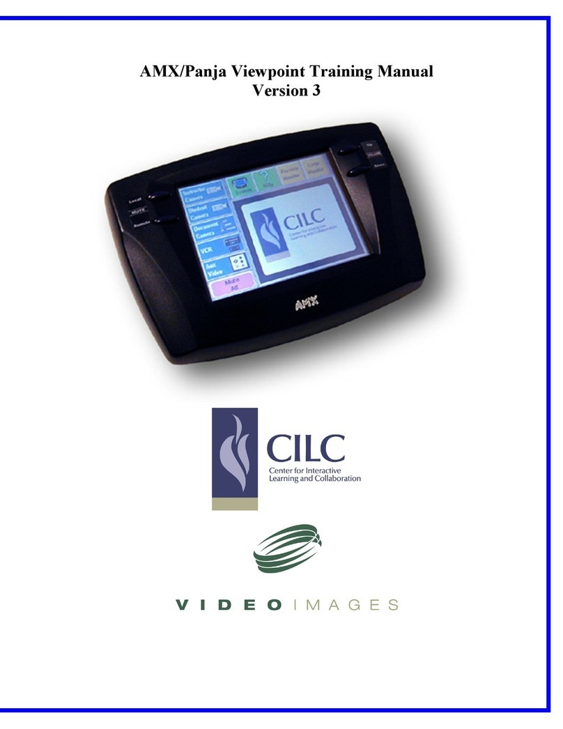
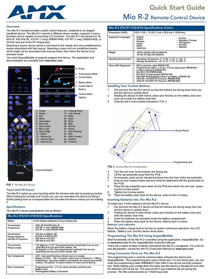
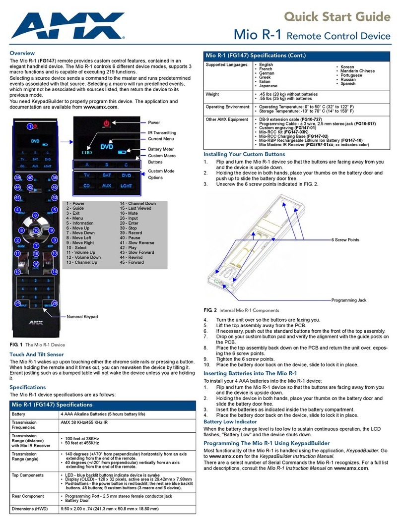
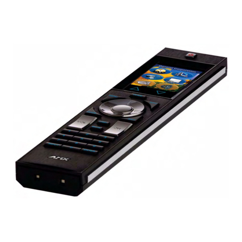
AMX AXP-CCV User manual

&DPHUD &RQWURO 6\VWHPV
$;30&&92$;00&&9 &RORU 9LGHR &DPHUD &HQWHUV
,QVWUXFWLRQ 0DQXDO

Limited Warranty and Disclaimer
AMX Corporation warrants its products to be free from defects in material and
workmanship under normal use for a period of three years from date of purchase
from AMX, with the following exceptions. Electroluminescent and LCD control
panels are warranted for a period of three years, except for the display and touch
overlay components which are warranted for a period of one year. Disk drive
mechanisms, pan/tilt heads, power supplies, modifications, MX Series products,
and KC Series products are warranted for a period of one year. Unless otherwise
specified, OEM and custom products are covered for a period of one year. AMX
software products are warranted for a period of 90 days. Batteries and incandescent
lamps are not covered.
This warranty extends to products purchased directly from AMX or an authorized
AMX dealer. Consumers should inquire from selling dealer as to the nature and
extent of the dealer’s warranty, if any.
AMX is not liable for any damages caused by its products or for the failure of its
products to perform, including any lost profits, lost savings, incidental damages, or
consequential damages. AMX is not liable for any claim made by a third party or
made by you for a third party.
This limitation of liability applies whether damages are sought, or a claim is made,
under this warranty or as a tort claim (including negligence and strict product
liability), a contract claim, or any other claim. This limitation of liability cannot be
waived or amended by any person. This limitation of liability will be effective even
if AMX or an authorized representative of AMX has been advised of the possibility
of any such damages. This limitation of liability, however, will not apply to claims
for personal injury.
Some states do not allow a limitation of how long an implied warranty lasts. Some
states do not allow the limitation or exclusion of incidental or consequential
damages for consumer products. In such states, the limitation or exclusion of the
Limited Warranty may not apply to you. This Limited Warranty gives you specific
legal rights. You may also have other rights that may vary from state to state. You
are advised to consult applicable state laws for full determination of your rights.
EXCEPT AS EXPRESSLY SET FORTH IN THIS WARRANTY, AMX MAKES NO
OTHER WARRANTIES, EXPRESSED OR IMPLIED, INCLUDING ANY IMPLIED
WARRANTIES OF MERCHANTABILITY OR FITNESS FOR A PARTICULAR
PURPOSE. AMX EXPRESSLY DISCLAIMS ALL WARRANTIES NOT STATED IN
THIS LIMITED WARRANTY. ANY IMPLIED WARRANTIES THAT MAY BE
IMPOSED BY LAW ARE LIMITED TO THE TERMS OF THIS LIMITED
WARRANTY.
AXP-CCV/AXM-CCV Color Video Camera Centers Table of Contents i
Table of Contents
Introduction ............................................................................ 1
Overview 1
Features 2
Application 3
What’s in this Manual 3
What’s New 4
Pre-Installation ....................................................................... 5
Overview 5
Setting the AXlink Device Numbers 5
Setting the Touch Panel device number 6
Verifying AXP-AI8 I/O DIP Switch Settings 9
Installation............................................................................ 11
Overview 11
Installing the AXP-CCV 11
Installing the AXM-CCV 12
Wiring the AXP-CCV and AXM-CCV 13
Preparing captive wires 14
Wiring guidelines 14
Using AXP-CCV mini-XLR connector for
AXlink data and power 15
Using AXP-CCV mini-XLR connector for
AXlink and an external 12 VDC power supply 15
Using AXM-CCV AXlink connector for
data and power 16
Using AXM-CCV AXlink connector for
data and an external 12 VDC power supply 17
Using a BNC video cable to provide video input 17
AXCESS Programming......................................................... 19
Overview 19
AXCESS software 19
Hardware Configuration 20
Channel Assignments 20
Levels 21

ii Table of Contents AXP-CCV/AXM-CCV Color Video Camera Centers
Mini-Color Touch Panel Pages 22
Specifications....................................................................... 27
Overview 27
Technical Support ................................................................ 29
Overview 29

AXP-CCV/AXM-CCV Color Video Camera Centers Introduction 1
Introduction
Overview
Connected to an AMX Control System via AXlink, the AXP-CCV (Figure 1) and
AXM-CCV (Figure 2) Color Video Camera Centers provide integrated,
programmable control of pan/tilt heads and lenses, VCRs, video codecs, video
switchers, monitors, and other equipment. Both of the camera centers combine
traditional dual-axis proportional-speed joystick camera controls with a Color Video
Mini-Touch Panel to give you graphic touch control and on-screen video monitoring
(with video input for NTSC/PAL). The touch panel’s icons and pushbuttons allow
you to select up to 6 cameras with up to 24 presets per camera. Optional software
provides 18 cameras and 8 preset controls.
AXlink supports up to 255 devices networked on a wire, running up to 3,000 feet
from the control system. In addition, AMX solutions are available for extending
operation over videoconferencing data ports, computer networks, Internet, and
other long-distance connections.
Figure 1
AXP-CCV Color Video
Camera Center (table-top
configuration)
Figure 2
AXM-CCV Color Video
Camera Center (rack-mount
configuration)

2Introduction AXP-CCV/AXM-CCV Color Video Camera Centers
Features
The AXP-CCV and AXM-CCV features include:
• Integrated AMX Color Video Mini-Touch Panel(s)
• Video input for NTSC/PAL monitoring on a 5-inch (127 mm) color active-
matrix LCD screen
• Two proportional x-y joysticks
• Two single-turn potentiometers (POTS)
• 22 programmable pushbuttons equipped with LED for feedback
• Engraved overlay with pushbutton functions and groupings
• Compatibility with all AXCESS Control Systems
• Tabletop mounting (AXP-CCV) or rack mounting (AXM-CCV)
For information about creating Touch Panel pages, refer to the Color Active-Matrix
Mini-LCD Touch Panel Instruction Manual.

AXP-CCV/AXM-CCV Color Video Camera Centers Introduction 3
Application
Figure 3shows a sample AXP-CCV system application.
AXP-CCV (rear view)
AXB-CAM (rear view)
AXB-EM232
(rear view)
4.2 amp, 12 VDC
power supply
Lens
Camera and controller
AXlink cable
6.3 amp, 12 VDC
Power supply
Stealth 1
AXB-F117
AXlink cable
Mini-XLR connector
BNC video cable
What’s in this Manual
This manual contains the following sections:
• Pre-Installation Settings Shows how to set the AXlink device numbers in
the AXP-CCV and AXM-CCV.
• Installation Describes the installation and wiring of the AXP-CCV and
AXM-CCV.
Figure 3
Sample AXP-CCV system
application

4Introduction AXP-CCV/AXM-CCV Color Video Camera Centers
• AXCESS Programming Lists AXCESS commands used by the AXP-CCV
and AXM-CCV program.
• Specifications Shows or lists AXP-CCV and AXM-CCV specifications.
• Technical Support Lists the telephone numbers to call for AMX technical
support.
What’s New
All new information, features, and operations added since the previous release of
this manual are identified with vertical margin bars:
• Revised the information in the Setting the Touch Panel device number section.
• Added information and drawings to the Wiring the AXP-CCV and AXM-CCV
and Specifications sections.

AXP-CCV/AXM-CCV Color Video Camera Centers Pre-Installation 5
Pre-Installation
Overview
This section describes how to set the AXlink device DIP switch, and the AXP-AI8
I/O DIP switch settings in the AXP-CCV and AXM-CCV.
Setting the AXlink Device Numbers
The AXlink device number range is 1 - 255. To set the AXP-CCV and AXM-CCV
AXlink device numbers:
1. Remove the Phillips-head screws from the rear panel.
2. Gently rotate the rear panel backward until you can lay it down flat exposing
the AXP-AI8. Locate the AXlink device DIP switch on the AXP-AI8 circuit card
(Figure 4).
AXlink device DIP
switch
Note
You must use unique AXlink
device numbers for the AXP-
AI8 and MCV to be re-
cognized by the AXCESS
Control System.
Figure 4
AXP-AI8 circuit card’s AXlink
device DIP switch location

6Pre-Installation AXP-CCV/AXM-CCV Color Video Camera Centers
3. Set the AXlink device number on the AXP-AI8 by setting DIP switch positions
1 - 8. The total value of all ON (up) positions on the DIP switch (Figure 5) sets
the device number. The AXlink DIP switch example shown in Figure 5is set to
129 (AXP-AI8 factory default).
1
2
3
4
5
6
7
8
ON
Position 1 2 3 4 5 6 7 8
Value 1 2 4 8 16 32 64 128
4. Once completed, place the rear panel back on, replace the screws, and gently
tighten the panel back into place.
Setting the Touch Panel device number
The device number identifies the Mini-Touch Panel within the AXCESS Control
System. Devices connected to the control system must be assigned unique AXlink
device numbers. Do not use duplicate device numbers to avoid communication
problems between the Mini-Touch Panel and control system. To set the device
number:
1. Ensure that a mini-XLR cable (for the AXP-CCV) or an AXlink cable (for the
AXM-CCV) is connected to the rear from the control system. It is this system
that is connected to a 12 VDC power supply. Once the CCV is receiving power,
the MAIN page (Figure 6) appears.
Figure 5
AXlink Device DIP switch
example and position values
Note
The device number takes
effect only on power-up. (This
occurs on the AXP-AI8 only).

AXP-CCV/AXM-CCV Color Video Camera Centers Pre-Installation 7
2. Press the SETUP button and the ADJUST ATTRIBUTES page (Figure 7)
appears. To access the CCV’s setup information, press PROTECTED SETUP.
Figure 6
MAIN page
Figure 7
ADJUST ATTRIBUTES page

8Pre-Installation AXP-CCV/AXM-CCV Color Video Camera Centers
3. After pressing PROTECTED SETUP, a setup screen (Figure 8) appears.
4. Press SET DEVICE to open the device number keypad of the CCV (Figure 9) and
enter a unique AXlink device number; the range is 1 through 255.
• CLEAR Clears the keypad number.
Figure 8
Setup screen
Figure 9
Device number keypad

AXP-CCV/AXM-CCV Color Video Camera Centers Pre-Installation 9
• ENTER Sets the device number, closes the keypad, and returns to the
Protected Setup page.
Verifying AXP-AI8 I/O DIP Switch Settings
The AXP-AI8 contains an eight-position DIP switch that is factory-set with positions
1 - 6 OFF (up) to enable joystick and speed control operation. Verify that the DIP
switch settings on the AXP-CCV and AXM-CCV match the settings shown in Figure
10. Refer to Setting the AXlink Device Numbers instructions to access the AXP-AI8
board.
I/O DIP switch
20-pin Berg header ribbon
cable connector
1 2 3 4 5 6 7 8
ON
Figure 10
AXP-AI8 circuit card’s I/O DIP
switch location
Note
For proper operation of the
CCV, the DIP switch must be
set as shown.

10 Pre-Installation AXP-CCV/AXM-CCV Color Video Camera Centers

AXP-CCV/AXM-CCV Color Video Camera Centers Installation 11
Installation
Overview
This section describes the wiring and installation of the AXP-CCV and AXM-CCV
Camera Centers. Since the AXP-CCV is a table-top configuration (Figure 11), it can
be mounted on any flat surface, whereas the AXM-CCV can be mounted within most
racks.
Installing the AXP-CCV
Front view and dimensions
15.50
(393.70 mm)
Side view and dimensions
7.25
(184.15 mm)
Figure 11
AXP-CCV Color Video
Camera Center (table-top
front/side view and
dimensions)

12 Installation AXP-CCV/AXM-CCV Color Video Camera Centers
To install the AXP-CCV:
1. Connect a BNC (male) video cable from the rear video connector to the video
source.
2. Position the AXP-CCV on a level surface.
3. Connect the AXP-CCV to the AXCESS system, using the 4-pin mini-XLR
connector, that is wired to an AXB-EM232 (powered by a 12 VDC power
supply). The mini-XLR (male) cable (Figure 16) is connected from the rear of the
AXB-EM232 to the rear of the AXP-CCV. Figure 17 shows another wiring option
that has an auxiliary power supply wired directly into the mini-XLR cable.
4. Connect a BNC video cable from the rear video connector to the video source.
Installing the AXM-CCV
You can mount the AXM-CCV into most types of electronic equipment racks. Figure
12 shows the front view of the AXM-CCV.
5.22
(132.60 mm)
19.00
(482.60 mm)
Front View and dimensions
Note
For more information, see the
Wiring guidelines subsection.
Figure 12
AXM-CCV Color Video
Camera Center (rack-mount
front/side view and
dimensions)

AXP-CCV/AXM-CCV Color Video Camera Centers Installation 13
To install the AXM-CCV:
1. Connect the 4-pin AXlink (male) connector to the rear of the panel using the
configuration in the Using AXM-CCV AXlink connector subsections.
2. Connect a BNC (male) video cable from the rear video connector to the video
source.
3. Insert the AXM-CCV into the equipment rack.
4. Line up the top left and bottom-right screw holes and start the #10-32 screws.
5. Then, start the bottom-left and top-right screws.
6. Then, tighten all the screws.
Wiring the AXP-CCV and AXM-CCV
The AXP-CCV and AXM-CCV communicate with the AXCESS Control System via
AXlink. The AXP-CCV contains a mini-XLR (female) connector on the rear panel for
AXlink communication and a BNC (female) video connection for video input as
shown in Figure 13.
Mini-XLR (female)
connector
BNC (female)
Video connector
The AXM-CCV contains a 4-pin AXlink (female) connector for AXlink
communication and a BNC (female) video connection for video input as shown in
Figure 14.
Figure 13
AXP-CCV rear panel mini-XLR
connector

14 Installation AXP-CCV/AXM-CCV Color Video Camera Centers
AXlink (female) connector site
BNC (female) video connector
Preparing captive wires
You will need a wire stripper, soldering iron, and flat-blade screwdriver to prepare
and connect the captive wires.
1. Strip 0.25 inch of wire insulation off all wires and apply a light coat of solder to
the ends using a soldering iron.
2. Insert each wire into the appropriate opening on the connector according to the
wiring diagrams and connector types described in this section.
3. Turn the flat-blade screws clockwise to secure the wire in the connector.
Wiring guidelines
The AXP-CCV and AXM-CCV require 12 VDC power to operate properly. The
AXCESS Control System supplies power via the AXlink cable or external auxiliary
12 VDC power supply. The maximum wiring distance between the control system
and camera centers is determined by power consumption, supplied voltage, and the
wire gauge used for the cable. Figure 15 lists wire sizes and the maximum lengths
allowable between the camera centers and control system. The maximum wiring
lengths for using AXlink power are based on a minimum of 13.5 VDC available at
the control system’s power supply.
Figure 14
AXM-CCV rear panel AXlink
connector (top view)
Caution
Do not connect power to the
camera center until the wiring
is complete. If you are using a
12 VDC power supply, apply
power to the panel only after
installation is complete.
Caution
Do not over-torque the screw.
Doing so can bend the seating
pin and damage the connector.

AXP-CCV/AXM-CCV Color Video Camera Centers Installation 15
Wiring guidelines
Wire Size Maximum Wiring
Length
18 AWG 142 feet
20 AWG 90 feet
22 AWG 56 feet
24 AWG 35 feet
If you install the camera centers farther away from the control system than
recommended in Figure 15, connect an external 12 VDC power supply to camera
centers according to the wiring diagrams described in this section.
Using AXP-CCV mini-XLR connector for AXlink data and power
Connect the control system’s AXlink connector to the mini-XLR connector (male) on
the rear panel of the AXP-CCV for data and 12 VDC power as shown in Figure 16.
1
2
3
4
Control system
GND -
2
1
PWR +
AXM
AXP
3
4
1 - GND -
3 - AXP
2 - AXM
4 - PWR +
4-pin mini-XLR connector
(external view)
Using AXP-CCV mini-XLR connector for AXlink and an external 12 VDC
power supply
Connect the control system’s AXlink connector to the mini-XLR connector and
external 12 VDC power supply to the rear panel of the AXP-CCV as shown in
Figure 17.
Figure 15
Wiring guidelines
Figure 16
Mini-XLR connector-to-control
system wiring diagram

16 Installation AXP-CCV/AXM-CCV Color Video Camera Centers
PWR +
Control system
1
2
3
4
GND -
12 VDC power supply
GND -
2
1
PWR +
AXM
AXP
3
4
1 - GND -
3 - AXP
2 - AXM
4 - PWR +
4-pin mini-XLR connector
(external view)
Using AXM-CCV AXlink connector for data and power
Connect the control system’s AXlink connector to the AXlink connector (male) on
the rear panel of the AXM-CCV, for data and 12 VDC power as shown in Figure 18.
PWR+
AXM
AXP
GND -
AXlink connector
Control system
PWR
AXM
AXP
GND
Figure 17
Mini-XLR connector to external
12 VDC power supply, and
control system wiring diagram
Caution
If you are using power from
AXlink, disconnect the wiring
from the control system before
wiring the AXM-CCV.
Figure 18
AXlink wiring diagram
Other manuals for AXP-CCV
1
This manual suits for next models
3
Table of contents
Other AMX Remote Control manuals

AMX
AMX MX-MM MobileMouse User manual

AMX
AMX Mio Modero Device Family Parts list manual

AMX
AMX UDM-RC05 User manual

AMX
AMX Mio Modero R-1 Parts list manual

AMX
AMX Mio Modero R-4 User manual

AMX
AMX MIO R-4 User manual

AMX
AMX NXA-AVB/RGB Guide

AMX
AMX Panja Viewpoint V3 Installation guide

AMX
AMX Mio Modero R-4 Parts list manual

AMX
AMX Mio R-2 Parts list manual