Installation Guide
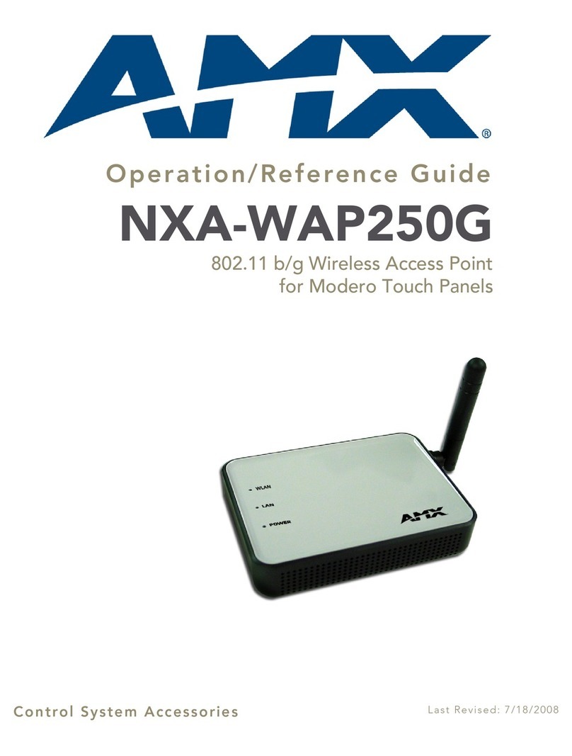
NXA-WAP250G 802.11b/g Wireless Access Point
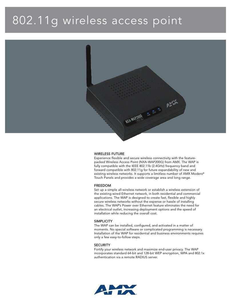
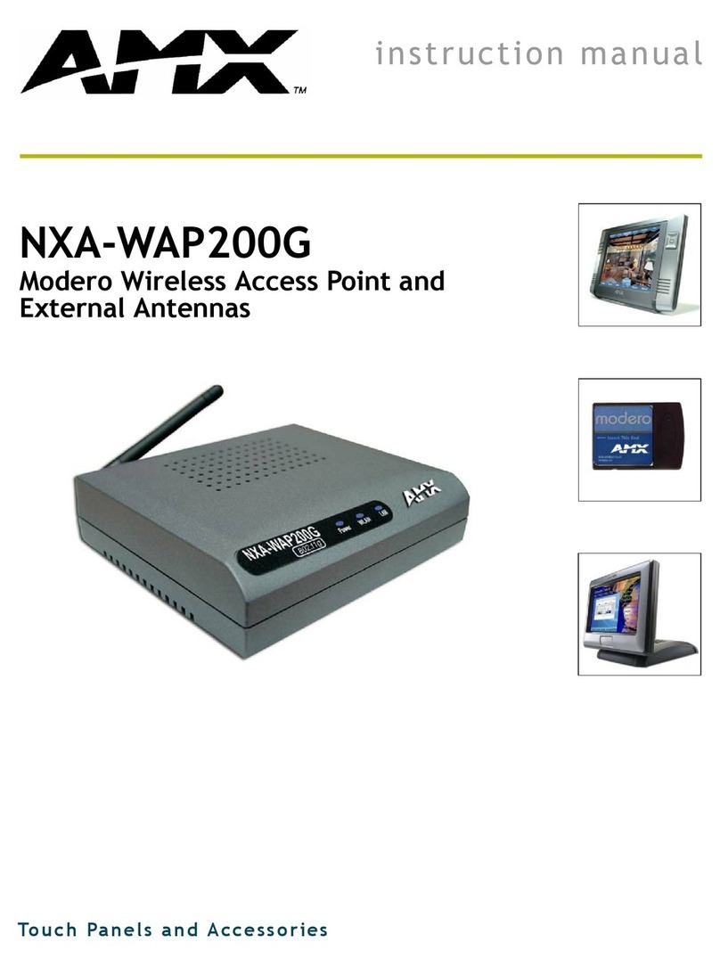
The NXA-WAP250G 802.11b/g Wireless Access Point (FG2255-50) provides both
high performance and increased security to support all of AMX's G4 Modero wireless
touch panels. The NXA-WAP250G (FIG. 1) provides convenient WLAN access for
office/home computers with connection speeds of up to 54Mbps. This Wi-Fi certified
WAP incorporates wireless encryption standards such as enterprise-grade WPA2,
WPA, 802.1x, and 64-bit/128-bit WEP encryption.
Additional Documentation
For more detailed installation, configuration and operating instructions including
troubleshooting wireless connectivity issues, refer to the NXA-WAP250G
Operation/Reference Guide (available online at www.amx.com).
Specifications
Power Connector
The access point does not have a power switch. It is powered on when connected to
the AC power adapter, and the power adapter is connected to a power source. The
power adapter automatically adjusts to any voltage between 100-240 volts at 50 or 60
Hz. No voltage range settings are required.
Ethernet Port
The access point has one 10BASE-T/100BASE-TX RJ-45 port that can be attached
directly to 10BASE-T/100BASE-TX LAN segments. These segments must conform to
the IEEE 802.3-2005 specifications.
This port supports automatic MDI/MDI-X operation, so you can use straight-through
cables for all network connections to PCs, switches, or hubs.
Reset Button
The Reset button is used to restart the access point or restore the factory default
configuration. If you hold down the button for less than 10 seconds, the access point
will perform a hardware reset. If you hold down the button for 10 seconds or more, any
configuration changes you may have made are removed, and the factory default
configuration is restored to the access point.
Hardware Installation
To install the Access Point, follow these steps:
1. Select a Site – Choose a proper place for the access point. For optimum
performance, consider these points:
• Mount the access point as high as possible above any obstructions in the
coverage area. Avoid mounting next to or near building support columns or other
obstructions.
• Mount away from any signal absorbing or reflecting structures (such as those
containing metal).
• Avoid radio interference by mounting away from other 802.11b or g wireless
devices.
2. Mount the Access Point – The access point is designed to be mounted on any
horizontal surface, such as a desktop, or on a wall. The access point can be
mounted on a wall by marking the position of the mounting screws (included) on
the wall so they line up with the two mounting slots on the bottom of the access
point. Set the screws into the wall, leaving about 3 mm (0.12 in.) clearance from
the wall. Then slide the access point down onto the screws.
3. Connect the Power Cord – Connect the power adapter to the access point, and
plug the power adapter into an AC power outlet.
CAUTION - Use ONLY the power adapter supplied with the access point. Otherwise,
the product may be damaged.
4. Observe the Indicator LEDs – When you power on the access point verify that
the POWER LED turns on and that the other LED indicators start functioning as
described under ”LED Indicators”.
5. Connect the Ethernet Cable – The access point can be connected to any 10 or
100 Mbps Ethernet network device, such as a hub or a switch. Connect your
network to the RJ-45 port on the back panel using category 3, 4, or 5 UTP
Ethernet cable. When the access point and the connected device are powered
on, the LAN LED should turn on indicating a valid network connection. If the LAN
LED fails to turn on, refer to Troubleshooting in the NXA-WAP250G
Operation/Reference Guide.
Note: The RJ-45 port on the access point supports automatic MDI/MDI-X operation,
so you can use straight-through cables for all network connections to PCs, switches,
or hubs.
Access Point Configuration
The access point can be configured by connecting a PC to its Ethernet port and
accessing the web interface. The default IP address of the access point is
192.168.1.240, with login user name “Admin” and default password “1988”.
For more information, refer to the Management Guide.
Twisted-Pair Cable Assignments
For 10/100BASE-TX connections, a twisted-pair cable must have two pairs of wires.
Each wire pair is identified by two different colors. For example, one wire might be
green and the other, green with white stripes. Also, an RJ-45 connector must be
attached to both ends of the cable.
CAUTION - Each wire pair must be attached to the RJ-45 connectors in a specific
orientation.
CAUTION - DO NOT plug a phone jack connector into the RJ-45 port. Use only
twisted-pair cables with RJ-45 connectors that conform with FCC standards.
The following figure illustrates how the pins on the RJ-45 connector are numbered. Be
sure to hold the connectors in the same orientation when attaching the wires to the
pins.
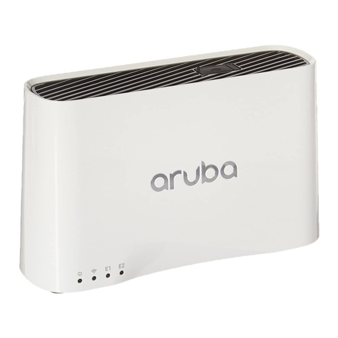
FIG. 1 NXA-WAP250G Wireless Access Point
NXA-WAP250G (FG2255-50) Specifications
Maximum Channels • FCC/IC: 1-11
• ETSI: 1-13
• MKK: 1-13
Maximum Clients 32 per VAP interface
Data Rate • 802.11g: 6, 9, 12, 18, 24, 36, 48, 54 Mbps per channel
• 802.11b: 1, 2, 5.5, 11 Mbps per channel
Modulation Type • 802.11g: CCK, BPSK, QPSK, OFDM
• 802.11b: CCK, BPSK, QPSK
Network Configuration Infrastructure
Operating Frequency • 2.4 ~ 2.4835 GHz (US, Canada, ETSI)
• 2.4 ~ 2.483 GHz (Japan)
Wireless Output Power • 802.11b: 18 dBm (typical)
• 802.11g: 17 dBm @ 6 Mbps, 14dBm @ 54 Mbps
Wireless Receive Sensitivity • 802.11b: -90 dBm @ 1 Mbps, -84 dBm @ 11 Mbps
• 802.11g: -86 dBm @ 6 Mbps, -68 dBm @ 54 Mbps
AC Power Adapter • Input: 100-240 VAC, 50-60 Hz
• Output: 5 VDC, 2 A
Unit Power Supply • DC Input: 5 VDC, 2 A maximum
• Power Consumption: 6.5 W maximum
LED Indicators • POWER (Power),
• LAN (Ethernet Link/Activity),
• WLAN (Wireless Link/Activity)
Network Management Web-browser
Temperature • Operating: 0 to 50 °C (32 to 122 °F)
• Storage: -20 to 70 °C (32 to 158 °F)
Humidity 15% to 95% (non-condensing)
Compliances • FCC Part 15B Class B
• EN 55022 Class B
• EN 55024
• EN61000-3-2
• EN61000-3-3
Standards • IEEE 802.3-2005 10BASE-T, 100BASE-TX
• IEEE 802.11b, g
• Wi-Fi 11b/g, WPA, WPA2, WMM
Radio Signal Certification • FCC Part 15C 15.247, 15.207 (2.4 GHz)
• EN 300-328
• EN 301 489-1
• EN 301 489-17
• ARIB STD-T66
• IC RSS-210
Safety • EN 60950-1
• IEC 60950-1 (CB)
Included Accessories: • AC power adapter set (includes 4 plug snaps)
• Category 5 (CAT5) network cable
• NXA-WAP250G Installation Guide
• WallMount/Surface mounting installation kit (including
two screws)
WLAN LED
LAN LED
POWER LED
Refer to the “LED Indicators”
section for details
FIG. 2 RJ-45 connector pinouts
