ANALOX ACG+ User manual

Analox Limited
15 Ellerbeck Court, Stokesley Business Park,
North Yorkshire, TS9 5PT, UK
UK/RoW T: +44 (0)1642 711400 F: +44 (0)1642 713900
US T: (714) 891-4478
W: www.analox.net E: info@analox.net
Copyright © 2014 Analox Ltd. All Rights Reserved.
ACG+
User Manual
Commercial in Confidence
The ACG+ must be returned to Analox in its
original storage and transit case.
Failure to do so may result in damage which
will be chargeable.


ACG+
User Manual Int. Approved
Document ref: P0149-801-09 January 2018 Page 1of 96
Copyright © 2014 Analox Ltd. All Rights Reserved.
Commercial in Confidence
List of contents
1Contents checklist......................................................................................................... 3
1.1 Standard contents................................................................................................................. 3
1.2 Optional accessories.............................................................................................................. 3
2Safety information ........................................................................................................ 4
2.1 Capabilities to test gases against the EN 12021:2014 standard .................................................. 4
2.2 Electrochemical sensors (oxygen and carbon monoxide) ............................................................ 4
2.3 PID lamp cleaning kit ............................................................................................................ 5
2.4 Inlet pressure & flow ............................................................................................................. 5
3Introduction ................................................................................................................. 6
3.1 ACG+ overview .................................................................................................................... 6
4Installation details ........................................................................................................ 7
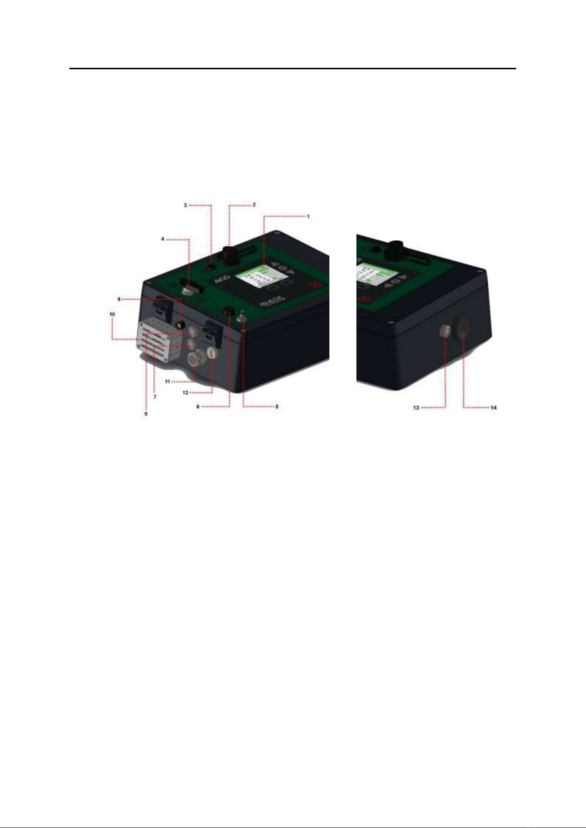
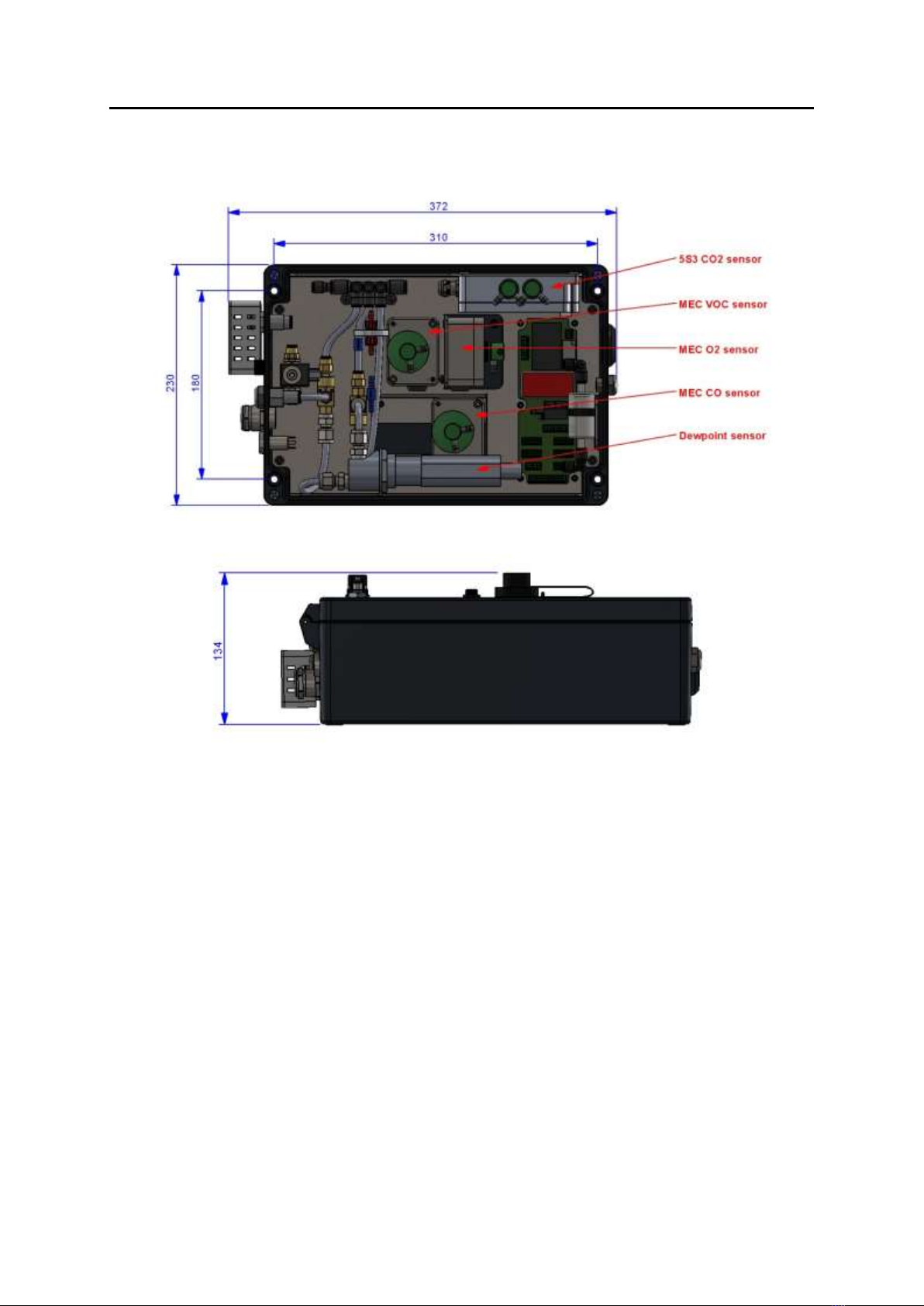
4.1 Mechanical overview ............................................................................................................. 7
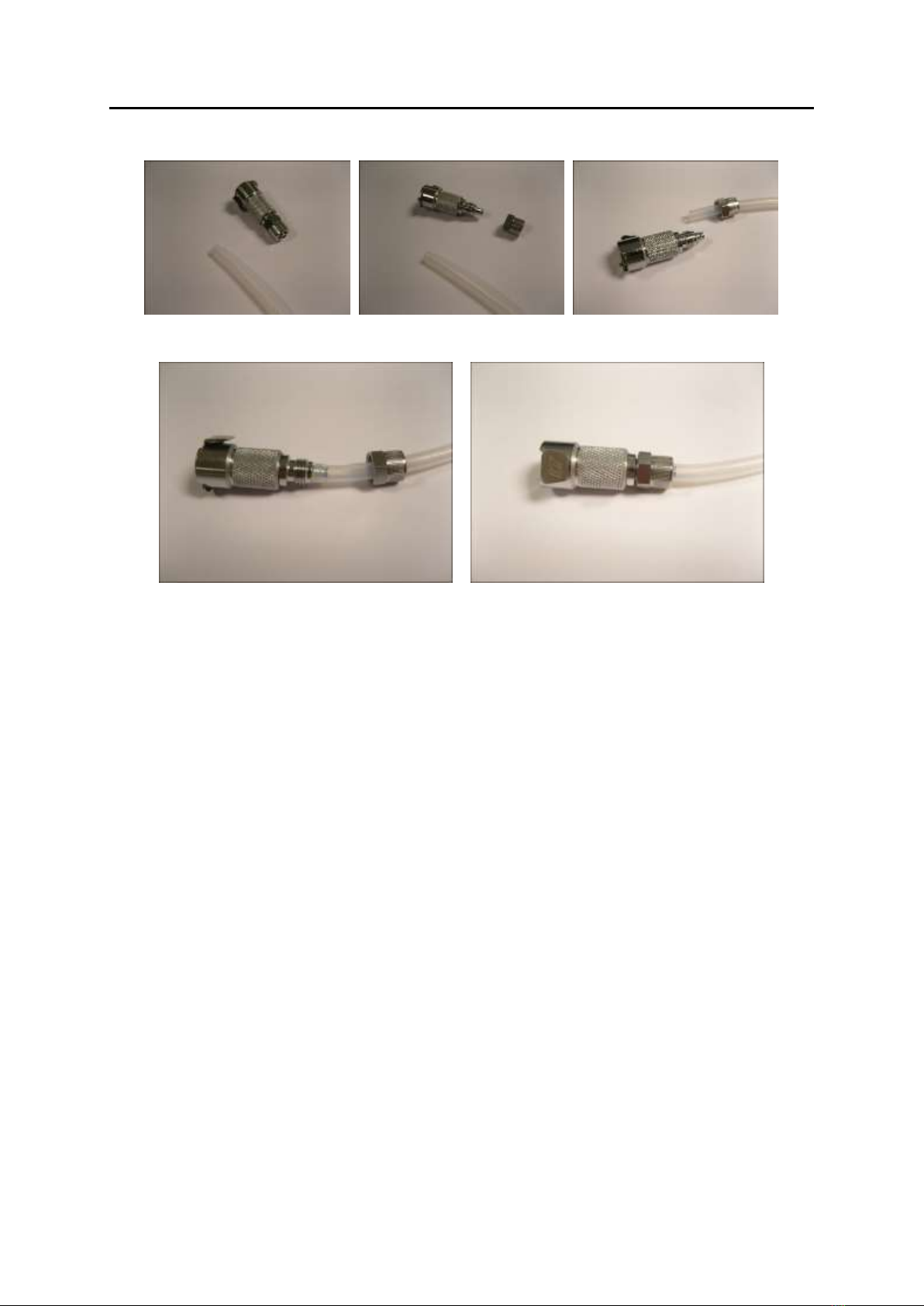
4.2 Gas sample connection (Both fixed and portable versions) ......................................................... 7
4.3 Installation (Portable)............................................................................................................ 9
4.4 Installation (Fixed)...............................................................................................................11
4.5 Safety interlock relay (ACG+ Fixed) .......................................................................................13
4.6 Safety interlock override key-switch (ACG+ Fixed)...................................................................14
4.7 Switched 24V DC outputs (ACG+ Fixed) .................................................................................15
5Operating instructions ................................................................................................. 16
5.1 Start-up..............................................................................................................................16
5.2 Controls..............................................................................................................................17
5.3 Inlet/purge valve .................................................................................................................18
5.4 Display ...............................................................................................................................18
5.5 Menu..................................................................................................................................19
5.6 Adjusting the backlight .........................................................................................................20
5.7 Power sub-menu..................................................................................................................20
5.8 System flow ........................................................................................................................21
5.9 Sensor readings...................................................................................................................22
5.10 Alarms................................................................................................................................24
5.11 Calibration adjustment .........................................................................................................27
5.12 Viewing device information....................................................................................................32
5.13 Viewing sensor information ...................................................................................................32
5.14 Data-logging .......................................................................................................................33
5.15 Sensor replacement reminder................................................................................................35
5.16 Timed sample draw ..............................................................................................................37
5.17 Setting the date and time .....................................................................................................39
6Configuration ............................................................................................................. 40
6.1 Software installation.............................................................................................................40
6.2 Making a connection.............................................................................................................55
6.3 Changing options .................................................................................................................56
6.4 Downloading data-logs .........................................................................................................57
6.5 Setting the time...................................................................................................................57
7Networking ................................................................................................................ 59
7.1 Overview ............................................................................................................................59
7.2 Connection..........................................................................................................................59
7.3 Transmission method ...........................................................................................................59
7.4 Setting the ACG Static IP Address ..........................................................................................60
7.5 Retrieving Data using TCP/IP Requests ...................................................................................61
7.6 Retrieving Data using UDP ....................................................................................................61
7.7 Datagram Structure .............................................................................................................62
8Troubleshooting.......................................................................................................... 68
8.1 System faults ......................................................................................................................68
9Recommended spares and accessories .......................................................................... 72
10 Maintenance requirements ....................................................................................... 74
10.1 Sensor & filter replacement ...................................................................................................74
10.2 Filter replacement................................................................................................................82
10.3 Service requirements ...........................................................................................................83
11 Specifications ......................................................................................................... 91
11.1 Instrument specification .......................................................................................................91
11.2 Sensor specification .............................................................................................................91
12 Declaration of conformity......................................................................................... 93

ACG+
User Manual Int. Approved
Document ref: P0149-801-09 January 2018 Page 2of 96
Copyright © 2014 Analox Ltd. All Rights Reserved.
Commercial in Confidence
List of tables
Table 1 Electrochemical sensor first aid procedures........................................................................ 4
Table 2 Connector J17 pin assignments.......................................................................................12
Table 3 Connector J3 pin assignments ........................................................................................12
Table 4 Relay and 24V output operation under fault and alarm conditions ........................................14
Table 5 Sensor status icons.......................................................................................................22
Table 6 Scaled hysteresis values ................................................................................................25
Table 7 Recommended calibration gas concentrations ...................................................................27
Table 8 Data-log formatting example..........................................................................................33
Table 9 List of system faults and possible solutions.......................................................................69
Table 10 List of sensor faults and possible solutions......................................................................70
Table 11 List of spares .............................................................................................................72
Table 12 List of accessories.......................................................................................................73
Table 13 Maintenance schedule of ACG+ components ...................................................................74
Table 14 Service schedule of ACG+ components ..........................................................................83

ACG+
User Manual Int. Approved
Document ref: P0149-801-09 January 2018 Page 3of 96
Copyright © 2014 Analox Ltd. All Rights Reserved.
Commercial in Confidence
1Contents checklist
1.1 Standard contents
1.1.1 Below is a list of standard contents which will be supplied to the customer
a) ACG+ unit (Including transport case)
b) USB lead
c) 0.1l/m restrictor kit (For sampling using Oil mist colorimetric tubes)
d) A printed copy of the user manual (A4 booklet)
e) Software CD
f) Test certificate
1.2 Optional accessories
1.2.1 Below is a partial list of optional accessories which could be supplied to the customer
depending on the order. The full spares & accessories list can be found on page 72.
a) Li-Ion rechargeable battery pack kit (Includes battery mounting case & charger)
b) NiMH rechargeable battery pack kit (Includes battery mounting case & charger)
c) External PSU (If not using rechargeable battery pack option, connection via front panel)
d) External PSU (For fixed installation using cable gland direct to interface PCB)
e) External beacon (For fixed units only)
f) Pressure regulator (2 stage)
g) Humidifier (For when the ACG+ is in constant use)
h) Mounting kit to install on either a solid wall or instrument panel (For fixed units only)
i) Gland and Override Keyswitch kit (For fixed units only)
The humidifier (g) should be installed if the ACG+ is going to be continuously connected for over 12 hours
to the compressed gas source with no exposure to ambient air. The humidifier is required to pull moisture
from the ambient air to re-hydrate the electrochemical cells within the ACG+. If dry gas is constantly
being passed over the sensors they will dry out and stop performing correctly.

ACG+
User Manual Int. Approved
Document ref: P0149-801-09 January 2018 Page 4of 96
Copyright © 2014 Analox Ltd. All Rights Reserved.
Commercial in Confidence
2Safety information
WARNING: Read the safety information fully before using the Analox ACG+.
2.1 Capabilities to test gases against the EN 12021:2014 standard
The ACG+ is partially capable to test gases against EN 12021:2014.
The ACG+ can test the following gas types from the standard:
•Breathing air
•Oxygen compatible air
•Nitrogen depleted air
2.2 Electrochemical sensors (oxygen and carbon monoxide)
Electrochemical sensors contain toxic compounds. Under normal conditions the sensor will be safely
sealed. To prevent leakage, the unit must not be exposed to temperatures outside the specified range, or
be exposed to organic vapours, which may cause physical damage to the body of the sensor. The unit
must not be stored in areas containing organic solvents or in flammable liquid stores.
When the life of the sensor has expired or it is leaking or otherwise damaged it must be disposed of safely
in accordance with local regulations.
The carbon monoxide cell contains an acidic electrolyte (sulphuric acid) whilst the oxygen cell contains
caustic electrolyte (potassium hydroxide). In the event of an accident, use the following first aid
procedures.
Table 1 Electrochemical sensor first aid procedures
Body
Part
Effect
First Aid Procedures
Skin
Contact could result in a chemical burn.
Persons with pre-existing skin
disorders may be more susceptible to
the effects of the substance.
Immediately flush the skin thoroughly
with water for at least 15 minutes.
Remove contaminated clothing and
wash before re-use.
Obtain medical advice if continued
irritation.
Ingestion
Corrosive. May cause sore throat,
abdominal pain, nausea, and severe
burns of the mouth, throat, and
stomach, and may be fatal.
If swallowed DO NOT INDUCE
VOMITING.
Wash out mouth thoroughly with water
and give plenty of water to drink.
Obtain medical advice immediately
Eye
Persons with pre-existing eye problems
may be more susceptible to the effects
of the substance.
Corrosive. May cause redness, pain,
blurred vision, and eye burns.
Contact can result in the permanent
loss of sight.
Irrigate thoroughly with water for at
least 15 minutes.
Obtain medical advice immediately.

ACG+
User Manual Int. Approved
Document ref: P0149-801-09 January 2018 Page 5of 96
Copyright © 2014 Analox Ltd. All Rights Reserved.
Commercial in Confidence
Body
Part
Effect
First Aid Procedures
Inhalation
Persons with pre-existing impaired
respiratory function may be more
susceptible to the effects of the
substance.
Inhalation is not an expected hazard
unless heated to high temperatures.
Mist or vapour inhalation can cause
irritation to the nose, throat, and upper
respiratory tract.
Remove to fresh air.
Rest and keep warm.
Obtain medical advice if applicable.
Should leakage of any electrolyte occur as a result of misuse, incorrect operation, manufacturing error,
physical damage, etc. then wear protective gloves when cleaning any spills. Should electrolyte contact
skin then the affected area should be washed thoroughly with copious water and medical advice sought if
there has been any contact with the eyes or mouth. If connected to any electrical equipment, the sensor
should be immediately removed.
2.3 PID lamp cleaning kit
The PID lamp cleaning kit (9300-1022) contains a vial of cleaning compound which contains alumina (CAS
Number 1344-28-1) as a very fine powder.
Hazard identification: May cause irritation of respiratory tract and eyes
Storage: Keep container closed to prevent water absorption and contamination
Handling:
•Do not breathe in the powder, avoid contact with skin, eyes and clothing
•Wear suitable protective clothing
•Follow industrial hygiene practices, wash face and hands thoroughly with soap and water after
use and before eating, drinking, smoking or applying cosmetics
•The powder carries a TVL (TWA) limit of 10mg/m3
2.4 Inlet pressure & flow
The system maximum inlet pressure is 10 bar gauge (145 psig). Ensure that appropriate pressure
reduction measures have been taken when connecting the sample inlet. Pressure relief is fitted to the unit
such that damage from over pressurisation is minimised but units may still be damaged.

ACG+
User Manual Int. Approved
Document ref: P0149-801-09 January 2018 Page 6of 96
Copyright © 2014 Analox Ltd. All Rights Reserved.
Commercial in Confidence
3Introduction
The ACG+ is a multi sensor gas analyser, specifically designed for the analysis of contaminants in
compressed breathing air. The ACG+ can be used as a portable instrument for use between compressors
on site or can be permanently connected to a compressor outlet, enabling you to continually verify the
quality of your breathing air. This delivers a much greater degree of system safety than a 3 or 6 month
spot check. The unit will provide continuous ‘on line’ monitoring of O2, CO2, CO, volatile organic compounds
(VOC) and water vapour in compressed breathing air lines.
3.1 ACG+ overview
Figure 1 - ACG+ overview
1) Display
2) USB port for data-download, with waterproof cap
3) Power connection (Via either optional rechargeable battery pack or external mains adaptor)
4) Gas inlet/purge valve
5) Gas inlet/calibration port
6) Sample support port
7) Exhaust
8) Exhaust
9) Breather
10) Humidifier (Optional)
11) M16 cable gland (Optional)
12) Override keyswitch (Optional)
13) Exhaust
14) Blow out blanking plug

ACG+
User Manual Int. Approved
Document ref: P0149-801-09 January 2018 Page 7of 96
Copyright © 2014 Analox Ltd. All Rights Reserved.
Commercial in Confidence
4Installation details
4.1 Mechanical overview
Figure 2 - ACG+ mechanical overview
4.2 Gas sample connection (Both fixed and portable versions)
•The sample gas inlet to the ACG+ must be at a regulated pressure in the range of 5 to 10 bar
gauge (72.5 to 145psig), taken directly from a sample line from a compressor, after all filtering
and regulation, which is supplying the bottles, air banks or breathing masks.
•The ACG+ is supplied with a 2m length of 6mmOD x 3mmID PTFE tubing which the
inlet/calibration adaptor should be connected to. Longer pipes can be used but purge times and
response times will be longer.
•It is recommended that a 2-stage regulator is used to maintain the sample gas inlet pressure
within operating limits.
•The ACG+ provides a Linktech panel mount coupling for the connection of the sample gas line or
calibration gas and also a Linktech inline socket (Which accepts up to ¼” OD tubing) for connection
to the ACG+ panel mount coupling.
•Before fitting the pipe-work the PTFE tubing should be fitted to the rear of the supplied Linktech
inline socket.
•The ID at one end of the PTFE tubing will require stretching slightly to fit over the rear of the
Linktech inline socket.

ACG+
User Manual Int. Approved
Document ref: P0149-801-09 January 2018 Page 8of 96
Copyright © 2014 Analox Ltd. All Rights Reserved.
Commercial in Confidence
•Remove the nut from the rear of the Linktech inline socket and place over the supplied length of
PTFE tubing.
•Fit the 6mmOD x 3mmID tubing over the end of the Linktech inline socket by slightly stretching
the inner of the tube so that it fits over the rear of the adaptor and secure in place with the nut.
•At the free end of the PTFE tubing, a compression nut should be fitted to connect to the regulated
pressure source.

ACG+
User Manual Int. Approved
Document ref: P0149-801-09 January 2018 Page 9of 96
Copyright © 2014 Analox Ltd. All Rights Reserved.
Commercial in Confidence
4.3 Installation (Portable)
The ACG+ Portable can be powered by either the optional rechargeable battery pack (Li-Ion or NiMH
variants) or an external PSU. Both options connect to the front panel power connector located next to the
USB port.
Gas connection should be made as per section 4.2
Figure 3 Typical ACG+ Portable installation
4.3.1 ACG+ power (Portable or fixed)
Power should be applied using either the optional rechargeable battery pack or the optional external PSU.
Connection should be made through the 3 way panel mount socket on the front panel located next to the
USB connector.
Battery Connected
Battery Connection

ACG+
User Manual Int. Approved
Document ref: P0149-801-09 January 2018 Page 10 of 96
Copyright © 2014 Analox Ltd. All Rights Reserved.
Commercial in Confidence
4.3.2 Charging the optional rechargeable battery pack
To charge the optional rechargeable battery pack the charger supplied with the battery pack kit MUST be
used as these are set to supply the correct power to the battery during charge.
Note: Using any other charger will invalidate your warranty.
•Connect the charger connector to the battery connection lead coming from the battery case (This
will only fit one way) and secure using the bayonet nut on the battery cable.
•Plug the charger into a mains supply, the charger will do a battery check prior to charging (For a
NiMH charger the LED will be yellow)
•If any faults are found the NiMH charger LED will flash orange/green, the Li-Ion chargers red LED
will extinguish.
•If all is okay the charger will then start to charge the battery (For NiMH chargers the LED will be
orange and for Li-Ion chargers the LED will be red).
•Once the charge is complete, the charger will go into trickle mode until disconnected (For a NiMH
charger the LED will go green, for Li-Ion chargers the red LED will extinguish).
•Once complete, disconnect the charger, the battery is then ready for connection to the ACG+.
NiMH Charger
Li-Ion Charger
External PSU Connection
External PSU Connected

ACG+
User Manual Int. Approved
Document ref: P0149-801-09 January 2018 Page 11 of 96
Copyright © 2014 Analox Ltd. All Rights Reserved.
Commercial in Confidence
4.4 Installation (Fixed)
4.4.1 Mounting details (ACG+ Fixed)
The ACG+ can be mounted as a fixed unit onto a wall or vertical flat surface using the enclosure mounting
holes. The minimum area required and the mounting centres for installing the ACG+ are shown in Figure
2.
Gas connection should be made as per section 4.2
Below shows a diagram of a typical fixed system setup.
Figure 4 Typical ACG+ Fixed installation
An optional mounting kit to install on either a solid wall or instrument panel can be purchased.
ACG+ mounting kit contents:
•4 x Socket head cap screw, M6x60mm.
•4 x M6 full nut, A4 SS.
•4 x M6 washer, A4 SS.
•4 x Multi wall fixing, M5 x 50mm (rubber insert and M5x50mm slotted screw).
4.4.2 Solid wall mounting (ACG+ Fixed)
•Mark on the wall the mounting hole drill positions and drill 10mm holes.
•Remove the M5x50mm screw from the rubber insert and fit the rubber inserts into the drilled
holes.
•Open the ACG+ lid and offer up the unit to the mounting surface.
•Place an M5x50mm slotted screw in each of the 4 enclosure mounting positions and screw in to
the previously fitted rubber inserts.
4.4.3 Panel mounting (ACG+ Fixed)
•Mark on the panel the mounting hole drill positions and drill 6.5mm holes.
•Open the ACG+ lid and offer up the unit to the mounting surface.
•Place a socket head cap screw in each of the 4 enclosure mounting positions and through the
drilled holes in the mounting panel.
•Fit an M6 washer over each of the screw thread at the back of the mounting panel.
•Fit an M6 full nut to the screw thread at the back of the mounting panel and fully tighten
(alternatively, the screws could be fitted into M6 tapped holes with the M6 nuts not required).

ACG+
User Manual Int. Approved
Document ref: P0149-801-09 January 2018 Page 12 of 96
Copyright © 2014 Analox Ltd. All Rights Reserved.
Commercial in Confidence
4.4.4 Electrical connection
The user terminals are located at J3 and J17 on the chassis PCB of the ACG+ as shown in Figure 5.
Figure 5 - Connector locations
Table 2 Connector J17 pin assignments
Connector J17 pin assignments
Terminal No.
Function
Details
1
ACG+ power (+ve)
9 to 36V DC, 24W max
2
ACG+ power (-ve)
3
Interlock relay contacts –
normally-open (1)
Volt-free relay contacts. 8A @ 24V max.
Relay contacts are normally open in
power off conditions. This pair of
contacts will be closed circuit under
nominal conditions and open circuit in
fault or alarm conditions (see section
4.5).
4
Interlock relay contacts –
normally-open (2)
5
Interlock relay contacts –
normally-closed (1)
Volt-free relay contacts. 8A @ 24V max.
Relay contacts are normally closed in
power off conditions. This pair of
contacts will be open circuit under
nominal conditions and closed circuit in
fault or alarm conditions (see section
4.5).
6
Interlock relay contacts –
normally-closed (2)
Table 3 Connector J3 pin assignments
Connector J3 pin assignments
Terminal No.
Function
Details
1
Solenoid drive (+ve)
Not for user connection
2
Solenoid drive (-ve)
3
Reserved
Not for user connection
4
Reserved

ACG+
User Manual Int. Approved
Document ref: P0149-801-09 January 2018 Page 13 of 96
Copyright © 2014 Analox Ltd. All Rights Reserved.
Commercial in Confidence
5
+24Vdc
Max total load of 500mA is available
between the 3 switched outputs
6
Output 1 –switched to 0V
7
Output 2 –switched to 0V
8
Output 3 –switched to 0V
Note: Max cross-sectional area for the terminals is 1.5mm2
4.4.5 ACG+ power (Fixed)
The ACG+ requires a power supply of 15 to 36V DC and will consume 20 Watts maximum. It is
recommended that power should be supplied using a screened, twisted pair cable, with the cable screen
clamped by the EMC cable gland, this should then be terminated to J17 pins 1 & 2 as shown.
4.5 Safety interlock relay (ACG+ Fixed)
The ACG+ has a double pole change-over relay that can be used to control external equipment in the
event of an alarm or fault condition.
Two sets of volt-free relay contacts are provided; a normally-open pair which are held closed under ideal
conditions, failing safe to their open state when a non-ideal state is identified and a normally-closed pair
which are held open under ideal conditions. Figure 6 shows the operational state of the relay under various
system conditions.
A typical use of the interlock relay might be to use the normally-open pair to cut power to a compressor
or to close a filling valve on an alarm, fault condition, or in the case of power loss. Alternatively, the
normally-closed pair can be used to activate external, self-powered alarm equipment such as a beacon.
Table 4 shows a typical example of the relay used in a system

ACG+
User Manual Int. Approved
Document ref: P0149-801-09 January 2018 Page 14 of 96
Copyright © 2014 Analox Ltd. All Rights Reserved.
Commercial in Confidence
Figure 6 Typical interlock relay wiring
4.6 Safety interlock override key-switch (ACG+ Fixed)
If an ACG+’s safety interlock relay (If fitted) is attached to external equipment, there may be
circumstances where it is not desirable for the ACG+ to disable the equipment attached under alarm or
fault conditions. The ACG+ provides an optional override key-switch, mounted on the left side of the unit.
With the key-switch set to ‘Normal’, the external equipment will be switched in the event of an alarm or
fault conditions. If the key-switch is set to the ‘Override’ position then the external equipment will not be
affected by alarm and fault conditions. Table 4 shows how the key-switch affects the various system
outputs.
Note: The safety interlock override key-switch only applies to equipment connected to the normally-open
pair of contacts (J17, pins 3 & 4).
Table 4 Relay and 24V output operation under fault and alarm conditions
System condition
Key-
switch
state
Interlock
relay
(normally-
open pair)
Interlock
relay
(normally-
closed pair)
Switched
24V
output 1
Switched
24V
output 2
Switched
24V
output 3
ACG+ power off
Normal
Open circuit
Closed circuit
Off
Off
Off
Override
Closed circuit
Ideal conditions (no
alarm or fault)
Normal or
override
Closed circuit
Open circuit
Off
Off
Off
Inlet alarm only (flow
or inlet pressure
alarm)
Normal or
override
Closed circuit
Open circuit
On
On
On
Sensor alarm active
Normal
Open circuit
Closed circuit
On
On
On
Override
Closed circuit
System or sensor
fault active
Normal
Open circuit
Closed circuit
On
On
On
Override
Closed circuit

ACG+
User Manual Int. Approved
Document ref: P0149-801-09 January 2018 Page 15 of 96
Copyright © 2014 Analox Ltd. All Rights Reserved.
Commercial in Confidence
4.7 Switched 24V DC outputs (ACG+ Fixed)
The ACG+ has 3 switched 24Vdc outputs that provide power to external equipment is the event of an
alarm condition or system fault. These can be used to power directly equipment such as, for example, a
beacon, an audible alarm, or to energise a relay. They can also be used as an input signal to an external
control system. Table 4 shows how the switched 24V outputs operate under various system conditions.
Figure 7 shows a typical example of the switched 24V DC outputs used in a system.
Figure 7 - Typical use of switched 24V outputs

ACG+
User Manual Int. Approved
Document ref: P0149-801-09 January 2018 Page 16 of 96
Copyright © 2014 Analox Ltd. All Rights Reserved.
Commercial in Confidence
5Operating instructions
5.1 Start-up
An ACG+ will automatically start up when power is supplied to it. Initially, the ACG+ will display a splash
screen as shown in Figure 8 which will be displayed for a few seconds after which the display will go blank
for up to 15 seconds. The ACG+ will then show the main display as described in section 5.4.1
Upon start-up, attached sensors may require a short time to warm up as described in section 5.9.3
Note: If any equipment used with the ACG+ is connected into the safety interlock relay (section 4.5),
then depending on the connection scheme, it may be necessary to switch the safety interlock key-switch
to the override position during start-up and until the sensors have stabilised on a steady gas flow. This
prevents any disruption to attached equipment during start-up due to any alarms (for example, a high
alarm due to atmospheric air present in internal plumbing).
Figure 8 - Start-up splash screen

ACG+
User Manual Int. Approved
Document ref: P0149-801-09 January 2018 Page 17 of 96
Copyright © 2014 Analox Ltd. All Rights Reserved.
Commercial in Confidence
5.2 Controls
Figure 9 shows the elements of the ACG+ front panel.
Figure 9 - ACG+ front panel
1) Display
2) Sample/Calibration gas inlet
3) Gas outlet for timed sample support (section 5.16)
4) Gas inlet/purge valve
5) External power connection (Either by rechargeable battery pack or external PSU)
6) USB port
7) Up button
8) OK button
9) Down button
10) Mute button
11) Context sensitive buttons (function depends on current context)

ACG+
User Manual Int. Approved
Document ref: P0149-801-09 January 2018 Page 18 of 96
Copyright © 2014 Analox Ltd. All Rights Reserved.
Commercial in Confidence
5.3 Inlet/purge valve
5.3.1 Use of the inlet/purge valve
The inlet/purge valve is used to control the flow of gas into the ACG+. It has two functions, firstly to turn
the flow of gas through the sensors on and off, and secondly to vent the inlet, to purge any stale gas in
the line.
Analox recommend that the purge system is used whenever a new pipe connection is made to the ACG+,
if the inlet line has been open to atmosphere or it has been exposed to damp gas. The following
instructions apply when using the supplied 2m PTFE pipe. If shorter or longer lengths of pipework are
used, the purge period should be adjusted accordingly, depending on the total pipe length. Only stainless
steel or PTFE/FEP pipework should be used to connect to the ACG+.
Starting with the valve in the “off” position, apply pressure to the inlet (Between 5 and 10 bar gauge)
using the supplied Linktech inlet/calibration connector.
Once pressure is applied, the valve should be turned to “Purge” and left for 2 minutes (Using the supplied
2m PTFE pipe) so that the pipework prior to the ACG+ can be purged of any stale, damp gas, and any
moisture on the pipe walls can be dried out.
Once the purge has completed, the valve can then be turned to the “On”position to allow the sensors to
start analysing the gas sample. This process will ensure the ACG+ sensors can stabilise as quickly as
possible to the gas you wish to measure.
5.4 Display
5.4.1 Main display screen
Under normal operation the ACG+ will display its main display screen. Figure 10 explains the elements of
the main screen.
Figure 10 - Main display overview
1. System status indicator
2. Live sensor readings
a. Sensor status icon
b. Sensor reading
c. Sensor type and display units
d. Sensor bar indicator
3. System information bar
4. Left context menu button (used to access menu in the case shown)
5. Right context menu button (used to access the system information page in the case shown).
5.4.2 System status indicator
The system status indicator shows the current status of the ACG+ system. If any alarm condition has been
identified then the system status indicator will turn red and display the word ‘Alarm’. If any system fault
Other manuals for ACG+
2
Table of contents
Other ANALOX Measuring Instrument manuals

ANALOX
ANALOX ACG+ Programming manual

ANALOX
ANALOX EII CO User manual

ANALOX
ANALOX ACG+ User manual

ANALOX
ANALOX ADM Aspida User manual

ANALOX
ANALOX Sub Aspida User manual

ANALOX
ANALOX Sub Mk III F User manual

ANALOX
ANALOX 1371 MK2 User manual

ANALOX
ANALOX ATA Pro User manual

ANALOX
ANALOX O2EII Pro User manual

ANALOX
ANALOX Ax60+ Multi-Gas User manual
Popular Measuring Instrument manuals by other brands

Palstar
Palstar PM2000AM Technical manual

ADS
ADS Intrinsically-Safe TRITON+ Installation, operation and maintenance manual

Stanley
Stanley CL2i user manual

Thorne & Derrick
Thorne & Derrick Rotronic HygroClip HC2-Ix25 quick start guide

Kroeplin
Kroeplin C0 Series user manual

Data Translation
Data Translation DT9812 Series user manual