manuals.online logo
Brands
  1. Home
  2. •
  3. Brands
  4. •
  5. ANALOX
  6. •
  7. Measuring Instrument
  8. •
  9. ANALOX ADM Aspida User manual

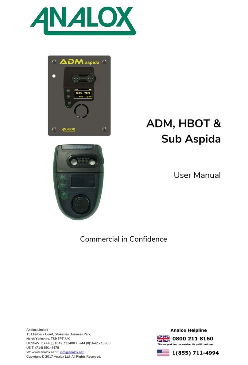
ANALOX ADM Aspida User manual

Oxygen sensor installation
Remove the top 4 screws from the device using a cross-head screwdriver as
shown. Retain the screws along with the sealing washers.
Gently remove the sensor cap as shown.
WARNING:
DO NOT TOUCH THE INSIDE OF THE
(INSTRUMENT OTHER THAN AS NOTED IN
THESE INSTRUCTIONS) WITHOUT
APPROPRIATE ANTI-STATIC PRECAUTIONS.
Remove the new sensor from its packaging. Oxygen sensors are supplied in
sealed bags. Before the bag is opened check that the sensor has not leaked.
If it has, then please refer to the safety information in the user manual.
Insert the sensor into the extraction tool, aligning the pins with the alignment
rib.
Align the extraction tool rib with the Aspida case alignment mark as shown.
Push the tool and sensor gently downwards into the case until the sensor
locates firmly within its socket.
Hold the top ring of the extraction tool gently, without squeezing the grip and
lift the tool vertically upwards to remove the extraction tool whilst leaving the
new sensor in place. (A gentle twisting of the tool may help to separate the tool
from the sensor).
Replace the sensor cap ensuring that the oxygen cell is centrally sited in the gas
port with the white gasket visible around the whole of the gas port. If
misaligned, remove the sensor cap, and adjust the oxygen cell position using
the extraction tool. Then refit the cap and recheck the alignment.
Holding the sensor cap in position, turn the unit over and fit the 4 crosshead
screws (including washers) into the rear of the case as shown.
WARNING
:
ANY NEW SENSOR FITTED TO A DEVICE
WILL TAKE TIME TO SETTLE TO A
STABLE READING. FOR THIS REASON,
ONCE THE SENSOR HAS BEEN FITTED,
THE DEVICE SHOULD BE LEFT UN-
POWERED FOR AT LEAST 2 HOURS
BEFORE ATTEMPTING TO POWER-UP
AND CALIBRATE.
Power the device and allow the sensor(s) to warm up. The new oxygen sensor
will require calibration and may be showing a fault due to an over-range
reading (this is possible for a new sensor).
NOTE:
THE OXYGEN SENSOR MAY REQUIRE
FURTHER FRESH AIR CALIBRATIONS AS THE
SENSOR CONTINUES TO SETTLE. THE
OXYGEN READING SHOULD BE CHECKED
FREQUENTLY IN FRESH AIR DURING THE
FIRST FEW HOURS OF OPERATION WITH A
NEW OXYGEN SENSOR.
To ensure the sensor replacement reminder ( icon) occurs at the correct time
for the new sensor, the reminder should be reset using the Aspida configuration
software. See the Aspida software configuration manual for instructions.
Aligned
Misaligned
ADM Aspida
Quick Start Guide
UK & RoW contact details:
15 Ellerbeck Court, Stokesley Business Park,
North Yorkshire, TS9 5PT, UK
T: +44 (0)1642 711400 F: +44 (0)1642 713900
W: www.analoxsensortechnology.com
E: i[email protected]
US contact details:
15121 Graham Street #B106,
Huntington Beach, California, 92649
T: (714) 891 4478 F: (714) 891 4479
W: www.analoxsensortechnology.com
E: ussales@analox.biz
Copyright © 2012 Analox Ltd. All Rights Reserved.
Optional Faceplate Installation Dimensions
Step 3. Switching the ADM Aspida On & Off
Safety Information
WARNING:
IF ENABLED, THE ADM ASPIDA USES
HIGH VOLUME WARNING ALARMS OF
UP TO 110DB (MANUALLY ACTIVATED
BY HOLDING THE BUTTON). TO
AVOID INJURY, MINIMISE EXPOSURE TO
THE SOUNDER.
WHERE FITTED, THE ELECTROCHEMICAL
OXYGEN SENSOR CONTAINS TOXIC
COMPOUNDS. TAKE CARE AND AVOID
CONTACT IF THIS IS DAMAGED.
CONSULT THE USER MANUAL FOR
FURTHER SAFETY INFORMATION.
Step 1. Fitting the ADM Aspida (with optional faceplate)
The Main Display
Package Contents Checklist
Step 2. Providing Power to the ADM Aspida
Disposal
WEEE statement
According to WEEE regulation this electronic product
cannot be placed in household waste bins. Please check
local regulations for information on the disposal of
electronic products in your area.
Analox will provide a disposal service if this is beneficial
to the customer. Analox are registered for the disposal of
WEEE in the UK through the Environment Agency (2013
Registration number WEE/KE0043SY).
Document Ref: P0132-800-05
•Analox ADM Aspida
•Oxygen sensor (Not shown)
•Oxygen sensor insertion/extraction
tool (Not shown)
•Universal charger power supply
•Calibration adapter (single or dual
including + 300mm of tubing)
•Test Certificate
•Quick Start Guide
•Optional faceplate assembly (as
applicable)
•Panel cut-out should be made as per the detail above.
•The cage nuts (available as part of the optional fixing kit –PN. P0132-
602) should be placed through the four holes and secured using the Pozi
Pan screws from the fixing kit, once tightened remove the screws.
•Connect the jack plug from the supplied PSU to the rear of the
instrument.
•Fit the flow adaptor and feed the pipe through the hole in the front
panel.
•Connect the free end of the pipework to the supply gas line using a
suitable 6mmOD pneumatic connector.
•Align the ADM Aspida mounting holes with the cage nuts in the panel
and secure with the supplied Pozi Pan screws.
WARNING:
THE ANALOX ADM ASPIDA SHOULD
ONLY USE NIMH BATTERIES –PN.
P0132-603. CONSULT THE USER
MANUAL FOR ADDITIONAL BATTERY
CHARGING SAFETY INFORMATION.
•With the mains charger disconnected from the wall outlet, insert the
power jack into the socket on the rear of the ADM Aspida prior to
instrument panel installation.
•Insert the mains charger into the wall outlet.
•Switch on the mains outlet.
•A full charge of the battery backup will complete within 4.5 hours.
NOTE:
ADM ASPIDA BATTERIES WILL
CHARGE WITH THE DEVICE BOTH
SWITCHED ON OR OFF.
To switch the ADM Aspida on, press the button.
NOTE:
ON START-UP, THE SENSORS HAVE A
SHORT WARM-UP PERIOD. LIVE GAS
VALUES ARE NOT DISPLAYED UNTIL
THE SENSORS HAVE COMPLETED THEIR
WARM-UP. FOR OXYGEN, THE WARM-
UP TAKES 15 SECONDS. FOR CARBON
DIOXIDE, THE WARM-UP TAKES 30
SECONDS. SENSOR WARM-UP WILL BE
SHOWN ON THE DISPLAY.
To switch off the device, from the main display press and hold the button
until the screen goes blank then release the button.
To return to the main display press and release the button as required to
exit the menus
1. Man-down detection enabled
icon (not used by ADM)
2. Clock
3. Measured gas types (dual
sensor)
4. Measured gas values (dual
sensor)
5. Measured gas units (dual
sensor)
6. Quiet mode enabled icon
7. Pressure (mbar –see manual)
8. Battery status icon
9. Measured gas type (single
sensor)
10. Measured gas value (single
sensor)
11. Measured gas units (single
sensor)
Consult the user manual for information on alarm, calibration and service
indicator icons which are also shown in the units area.
Service and Support
If you require technical or service support, please visit:
https://www.analoxsensortechnology.com/tech-and-
service-support.html
Scan the QR code to
visit the Analox ADM
Aspida web page
Single
Dual
Oxygen sensor installation
NOTE:
FOR OXYGEN SENSOR INSTALLATION,
SEE THE REVERSE SIDE OF THIS QUICK
START GUIDE
Other manuals for ADM Aspida

1

Other ANALOX Measuring Instrument manuals

ANALOX ACG+ User manual

ANALOX

ANALOX ACG+ User manual

ANALOX O2EII Pro User manual

ANALOX

ANALOX O2EII Pro User manual

ANALOX ACG+ User manual

ANALOX

ANALOX ACG+ User manual

ANALOX 1371 MK2 User manual

ANALOX

ANALOX 1371 MK2 User manual

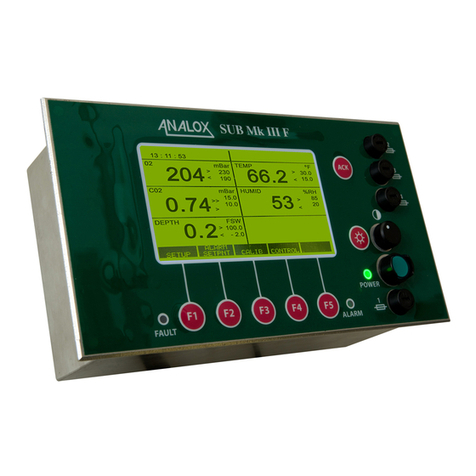
ANALOX Sub Aspida User manual

ANALOX

ANALOX Sub Aspida User manual

ANALOX Ax60+ Multi-Gas User manual

ANALOX

ANALOX Ax60+ Multi-Gas User manual

ANALOX Sub Mk III F User manual

ANALOX

ANALOX Sub Mk III F User manual

ANALOX ATA Pro User manual

ANALOX

ANALOX ATA Pro User manual

ANALOX EII CO User manual

ANALOX

ANALOX EII CO User manual

ANALOX ACG+ Programming manual

ANALOX

ANALOX ACG+ Programming manual

Popular Measuring Instrument manuals by other brands

Siemens SITRANS F M MAGFLO operating manual

Siemens

Siemens SITRANS F M MAGFLO operating manual

Stanley CL2i user manual

Stanley

Stanley CL2i user manual

PulseTech 390PT operating instructions

PulseTech

PulseTech 390PT operating instructions

Ossenberg INFRAGAS-109 Operation and maintenance manual

Ossenberg

Ossenberg INFRAGAS-109 Operation and maintenance manual

AST A250C PL user manual

AST

AST A250C PL user manual

Endress+Hauser Proline Prosonic Flow 93 Function manual

Endress+Hauser

Endress+Hauser Proline Prosonic Flow 93 Function manual

gefran 650 L Installation and instruction manual

gefran

gefran 650 L Installation and instruction manual

AEMC MN306 user manual

AEMC

AEMC MN306 user manual

TIMEDOX Silver Plus quick start guide

TIMEDOX

TIMEDOX Silver Plus quick start guide

AmpliVox 170 Operation manual

AmpliVox

AmpliVox 170 Operation manual

Tektronix VM700T Programmer's manual

Tektronix

Tektronix VM700T Programmer's manual

HT HT9019 user manual

HT

HT HT9019 user manual

Huma-i White HI-100 user manual

Huma-i

Huma-i White HI-100 user manual

Keysight PNA-X N5244A Service guide

Keysight

Keysight PNA-X N5244A Service guide

Bruker CTX manual

Bruker

Bruker CTX manual

Ludlum Measurements 3003 user manual

Ludlum Measurements

Ludlum Measurements 3003 user manual

Omntec FuelCheck Installation & operating manual

Omntec

Omntec FuelCheck Installation & operating manual

LaMotte 1705-EU manual

LaMotte

LaMotte 1705-EU manual

manuals.online logo
manuals.online logoBrands
  • About & Mission
  • Contact us
  • Privacy Policy
  • Terms and Conditions

Copyright 2025 Manuals.Online. All Rights Reserved.