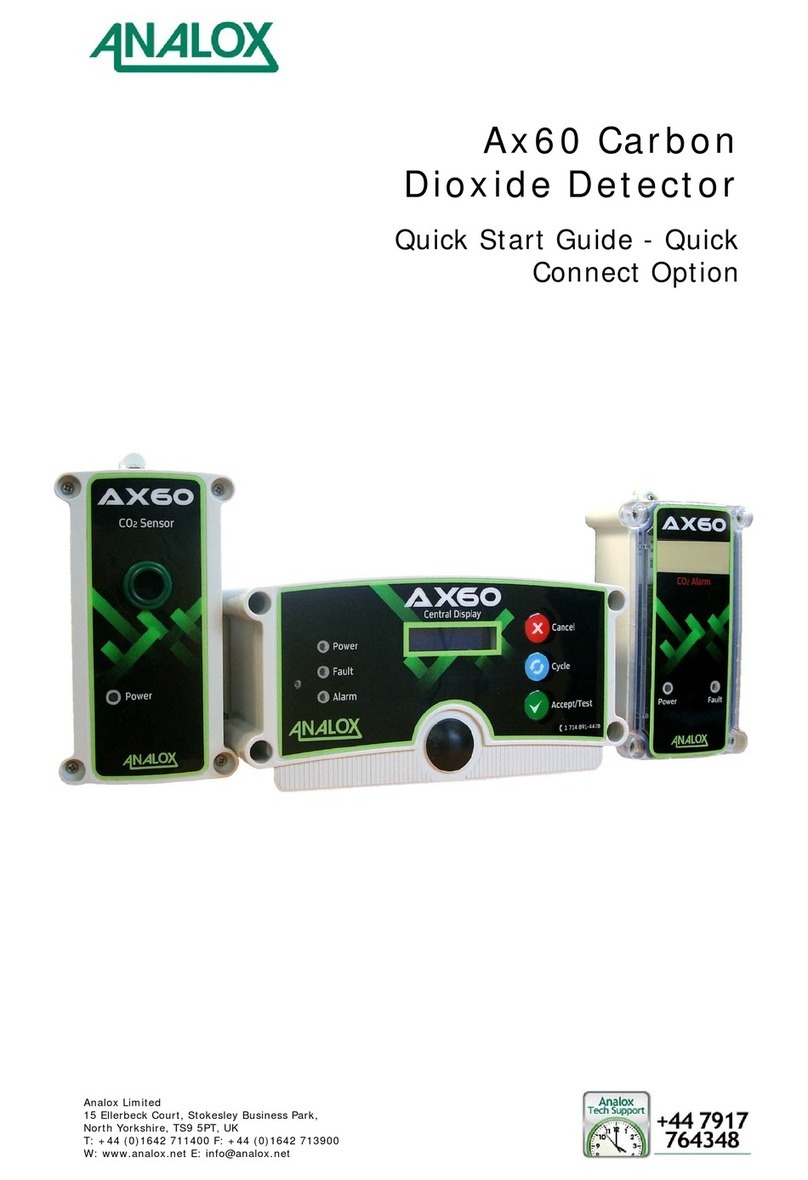
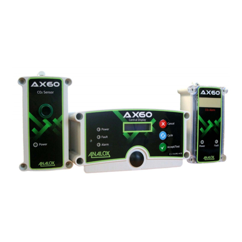
ANALOX A50 User manual


A50 Carbon Dioxide Detector
User Manual Int. Approved
Document ref: P0204-8000-03 July 2021 Page 3 of 27
Commercial in Confidence
List of Contents
1. Safety Notes....................................................................................................................4
2. Packaging Contents Check............................................................................................4
3. About the A50 ................................................................................................................5
4. A50 Accessories ..............................................................................................................6
5. Effects of carbon dioxide...............................................................................................7
6. Installation ......................................................................................................................8
6.1. How to fit an A50..................................................................................................................................................... 8
6.2. Remote Alarm Repeaters....................................................................................................................................12
6.2.1. To connect a “Hard Wired” Remote Alarm Repeater ...............................................................................................12
6.2.2. To connect a “Quick Connect” Remote Alarm Repeater.........................................................................................13
6.3. Cleaning.....................................................................................................................................................................13
7. Operation ......................................................................................................................14
7.1. Operation at Altitude ...........................................................................................................................................14
8. Alarm Indications .........................................................................................................15
8.1. Standard Unit ..........................................................................................................................................................15
8.2. TWA (Time Weighted Average) .......................................................................................................................15
8.3. Lamp and Alarm Test ...........................................................................................................................................15
8.3.1. Summary of Status Indicator Lamps................................................................................................................................16
9. Instrument Calibration & Test ....................................................................................17
9.1. Zero calibration adjustment..............................................................................................................................17
9.2. Alarm Test.................................................................................................................................................................19
9.3. Adjusting the Alarm Setpoints .........................................................................................................................20
9.3.1. Adjusting Alarm Setpoints...................................................................................................................................................20
10. Menu Navigation Flow Chart......................................................................................21
11. Technical Specifications...............................................................................................22
12. Disposal.........................................................................................................................23
13. Product variants ...........................................................................................................24
13.1. Part Number Matrix..............................................................................................................................................24
14. Warranty Information..................................................................................................25
15. Declaration of Conformity ..........................................................................................26
16. UK Declaration of Conformity ....................................................................................27

A50 Carbon Dioxide Detector
User Manual Int. Approved
Document ref: P0204-8000-03 July 2021 Page 4 of 27
Commercial in Confidence
1. Safety Notes
Every gas monitor installation should be risk assessed. The correct location of monitor(s) must
consider the potential sources of gas leaks and the location of expected human occupation in the
area. Where large areas must be monitored, it is often advised that no single monitor should cover a
volume in excess of 80m3. The installation of more monitors should be considered where an area is
complex in shape, filled with obstacles, has a lack ventilation or air circulation, or if there are dead
zones where gas can collect.
a) The A50 must be installed according to these instructions which should be read entirely
before commencing installation.
b) For your convenience the Remote Alarm Repeater cable is pre-wired to the A50 sensor unit.
c) The system MUST NOT be switched on until all connections have been correctly made.
d) We do not recommend you access the main unit. Potentially lethal voltages exist within the
A50. It should only be opened by a Qualified Technician and must be isolated from the
electrical supply before opening.
e) A proof test should be carried out at least 30 minutes after installation or relocation of the
unit, and then at least every 18 months.
2. Packaging Contents Check
The following items are enclosed:
a) A50 main unit with power lead and 8 metres of interconnecting cable for connection to the
Remote Alarm Repeater
b) A50 quick start guide or user manual
c) Test certificate
d) Wall plugs and screws for wall mounting
e) Remote Alarm Repeater
f) Warning label

A50 Carbon Dioxide Detector
User Manual Int. Approved
Document ref: P0204-8000-03 July 2021 Page 5 of 27
Commercial in Confidence
3. About the A50
The A50 is designed to detect the presence of carbon dioxide in ambient air for the protection of
people in confined spaces. The A50 provides audible and visual indication of potentially dangerous
levels of carbon dioxide in the air surrounding the instrument. The instrument uses an infrared
detector system, together with state of the art technology. It is housed in an IP65 splash proof
enclosure, and is designed to provide long, trouble free service, with minimum maintenance. The
Remote Alarm Repeater mimics the status indicators on the A50 unit. It also provides a push-button
which operates in the same manner as the Mode button on the A50.
If you have more than one entrance to your cellar or store room you may need more than one
Remote Alarm Repeater. Up to three repeaters can be daisy chained (one repeater linked to another)
covering up to three entrance doors.
Optional items fitted to, or supplied with the unit may include the following (as shown in the
photographs on Page 6):
a) Splash guard
b) Extra Remote Alarm Repeaters
c) Calibration gasses

A50 Carbon Dioxide Detector
User Manual Int. Approved
Document ref: P0204-8000-03 July 2021 Page 6 of 27
Commercial in Confidence
4. A50 Accessories
NOTE:
* -ITEMS A & B ARE CONSIDERED AS ACCESSORIES FOR SAFETY
OPERATION OF THE EQUIPMENT, ONLY ANALOX SUPPLIED
ACCESSORIES TO BE USED.
A*
B*
C

A50 Carbon Dioxide Detector
User Manual Int. Approved
Document ref: P0204-8000-03 July 2021 Page 7 of 27
Commercial in Confidence
5. Effects of carbon dioxide
1.000 ppm
(0,1%)
5.000 ppm
(0,5%)
10.000 ppm
(1%)
15.000 ppm
(1,5%)
20.000 ppm
(2%)
30.000 ppm
(3 %)
40.000-
50.000 ppm
(4-5%)
50.000-
100.000 ppm
(5-10%)
100.000-
1.000.000 ppm
(10-100 %)
For a more detailed outline of the dangers of CO2, please visit our website
www.analoxgroup.com

A50 Carbon Dioxide Detector
User Manual Int. Approved
Document ref: P0204-8000-03 July 2021 Page 8 of 27
Commercial in Confidence
6. Installation
6.1. How to fit an A50
CAUTION:
CARBON DIOXIDE GAS (CO2) IS HEAVIER THAN AIR AND
SHOULD BE MONITORED FROM A LOW HEIGHT. YOU
SHOULD THEREFORE INSTALL THE CO2SENSOR AT A
HEIGHT OF 12–18" (305–457MM) ABOVE THE FLOOR LEVEL.
NOTE:
FOR OPTIMAL PERFORMANCE, IF THERE IS A LARGE
VARIANCE BETWEEN WHERE UNITS ARE STORED AND
WHERE THEY ARE INSTALLED, IT IS RECOMMENDED THAT
UP TO 2 HOURS IS ALLOWED AFTER INSTALLATION BEFORE
APPLYING POWER. THIS IS TO ALLOW FOR TEMPERATURE
STABILIZATION IN THE UNIT WHICH IS IMPORTANT FOR
DEVICE ACCURACY.
1] The Remote Alarm Repeater should be located at eye level and attached to the outside
or immediately inside the access door. Remote

A50 Carbon Dioxide Detector
User Manual Int. Approved
Document ref: P0204-8000-03 July 2021 Page 9 of 27
Commercial in Confidence
2] Attach the main unit to the wall 305-457mm from the floor as close to the valves and
manifolds as possible.
3] A drilling template is included with this booklet.

A50 Carbon Dioxide Detector
User Manual Int. Approved
Document ref: P0204-8000-03 July 2021 Page 10 of 27
Commercial in Confidence
4] The A50 should be mounted onto a wall using the mounting lugs on the unit. Wall plugs
and screws are provided for this purpose. It is not necessary to dismantle the A50 main
unit in any way prior to installation.
5] An 8 metre 8 core cable is pre-wired to the A50. Run the Remote Alarm Repeater cable
to the outlet door, safely securing the cable with cable clips then wire up to the Alarm
Repeater.
Mains input
Repeater output

A50 Carbon Dioxide Detector
User Manual Int. Approved
Document ref: P0204-8000-03 July 2021 Page 11 of 27
Commercial in Confidence
6] If the power supply for the A50 is not positioned so that it is close to the equipment and
in easy reach of the operator, a local means of double pole isolation must be provided.
Isolation can be achieved either by means of a non-locking plug or a double pole switch
of suitable rating.
7] A label must be placed by the local disconnection point for the A50 stating: "REMOVE
PLUG TO DISCONNECT A50"
8] Alarm Repeater connection can be achieved as per section 6.2
NOTE:
FIT THE SUPPLIED WARNING SIGN NEXT TO THE REPEATER
Repeater connections (Hard wired shown)

A50 Carbon Dioxide Detector
User Manual Int. Approved
Document ref: P0204-8000-03 July 2021 Page 12 of 27
Commercial in Confidence
6.2. Remote Alarm Repeaters
6.2.1. To connect a “Hard Wired”Remote Alarm Repeater
1] Disconnect the power supply from the A50.
2] Open the Remote Alarm Repeater unit by removing the 4 screws in the front of the case
and carefully pulling the case apart. The connecting wires from the A50 pass through
one of the cable glands on the Remote Alarm Repeater.
3] Terminate the wires in
accordance with Table 1:
4] Replace the lid of the Remote
Alarm Repeater, insert and
tighten the 4 screws, and mount
it in the desired position using
the supplied wall plugs and
screws.
5] Restore power to the A50. Press
the Mode button on the Remote
Alarm Repeater once, and
ensure that the four indicators
flash.
REPEATER CABLE COLOURS
Type 2 (Cat 5)
Repeater
Term
8
7
6
5
4
3
2
1
Table 1 Repeater wiring

A50 Carbon Dioxide Detector
User Manual Int. Approved
Document ref: P0204-8000-03 July 2021 Page 13 of 27
Commercial in Confidence
6.2.2. To connect a “Quick Connect” Remote Alarm Repeater
1] Disconnect the power supply from the A50.
2] Insert the connector on the end of the wire into either socket on the bottom of the
Remote Alarm Repeater.
3] Restore power to the A50. Press the Mode button on the Remote Alarm Repeater once,
and ensure that the four indicators flash.
NOTE:
IN THE PRESENCE OF A GENUINE ALARM, THIS TEST
FEATURE IS DISABLED.
6.3. Cleaning
CAUTION:
DO NOT ATTEMPT TO CLEAN THE A50 WITH HIGH
PRESSURE EQUIPMENT OR DIRECT WATER SPRAY
All parts of the A50 may be cleaned with a soft cloth, moistened with water.

A50 Carbon Dioxide Detector
User Manual Int. Approved
Document ref: P0204-8000-03 July 2021 Page 14 of 27
Commercial in Confidence
7. Operation
When mains power is first applied to the A50, it requires a period of approximately 40 seconds to
stabilise. During this period, the OK and Fault status indicators will be turned on. The OK status
indicator will flash briefly every few seconds, indicating normal operation and after the initial
stabilising period has expired, the Fault status indicator will turn off. The A50 will then be in its normal
operating condition. During normal operation, the OK status indicator will flash on and off, thus
indicating that the system is operating correctly. The OK status indicator on any Remote Alarm
Repeaters will also flash on and off.
7.1. Operation at Altitude
The toxic effects of carbon dioxide are dependent on the partial pressure, or the quantity of gas
molecules, not the percentage in the atmosphere; therefore at altitudes above 900 metres (3000 feet)
alarms will operate below the factory calibration point. Please refer to the A50 CO2Monitor –Use at
high altitude document for details of suitable alarm set points and calibration procedures at altitude.

A50 Carbon Dioxide Detector
User Manual Int. Approved
Document ref: P0204-8000-03 July 2021 Page 15 of 27
Commercial in Confidence
8. Alarm Indications
8.1. Standard Unit
If the A50 detects a carbon dioxide concentration which exceeds the first alarm level, the red Alarm 1
status indicator will begin to flash and the Horn will sound.
If the measured concentration of carbon dioxide continues to rise above the second alarm level, then
the Alarm 2 status indicator will also begin to flash and the pace of the Horn will increase. This
condition will be repeated on any Remote Alarm Repeaters. The alarms are self-cancelling when the
carbon dioxide level falls below the alarm limits.
NOTE:
FOR LATCHED SYSTEMS, ALARMS WILL CONTINUE TO SOUND
AFTER THE GAS CONCENTRATION HAS FALLEN BELOW THE
ALARM SET POINT UNTIL THE MODE BUTTON IS PRESSED
Alarm 1
Alarm 2
8.2. TWA (Time Weighted Average)
The A50 continuously monitors for elevated carbon dioxide concentrations above ambient, but below
the first alarm. If the average carbon dioxide concentration over an 8 hour period is in excess of
5000ppm, the A50 will indicate a TWA alarm by slowly flashing the OK and Alarm 1 status indicators.
NOTE:
HIGHER CONCENTRATIONS WILL ACTIVATE THE TWA ALARM
QUICKER.
A TWA alarm will only clear when the average carbon dioxide concentration over an 8 hour period
falls to below 5000ppm. The TWA alarm is self-cancelling when the average carbon dioxide level falls
below the alarm limits.
8.3. Lamp and Alarm Test
Momentarily pressing the Mode button on either the A50 or any Remote Alarm Repeater, in the
absence of any alarm conditions, causes a lamp and alarm test to be performed. The status indicators
will flash 4 times, together with the horn. This test should be carried out each time the area is entered
or at the start of each shift.

A50 Carbon Dioxide Detector
User Manual Int. Approved
Document ref: P0204-8000-03 July 2021 Page 16 of 27
Commercial in Confidence
8.3.1. Summary of Status Indicator Lamps
OK LAMP
(GREEN)
ALARM1 LAMP
(RED)
ALARM2 LAMP
(RED)
FAULT LAMP
(YELLOW)
MEANING
OFF
OFF
OFF
OFF
Instrument power is off, check
power and fuses
ON/ BLIP OFF
OFF
OFF
ON
40 second warmup
ON/ BLIP OFF
OFF
OFF
OFF
Normal Operation
FLASHING
FLASHING
OFF
OFF
TWA alarm *
OFF
FLASHING AND
SLOW BUZZER
OFF
OFF
CO2 Level is > AL1 *
OFF
FLASHING
FLASHING AND
MED. BUZZER
OFF
CO2 Level is >AL2% *
ON
OFF
OFF
OFF
Built in test fail **
OFF
OFF
OFF
FLASHING AND
SLOW BUZZER
Internal Fault**
OFF
OFF
OFF
FLASHING AND
MED. BUZZER
Detector Fault**
OFF
OFF
OFF
FLASHING AND
FAST BUZZER
I.R. Source Fault***
NOTE: *
IF THIS ALARM IS BELIEVED TO BE INCORRECT, CARRY OUT A
ZERO CALIBRATION ADJUSTMENT.
NOTE: **
POWER CYCLE THE SYSTEM. IF FAULT DOES NOT CLEAR,
CONTACT YOUR SERVICE PROVIDER.
NOTE: ***
AN IR SOURCE FAULT WILL NECESSITATE RETURNING THE UNIT
FOR REPAIR.

A50 Carbon Dioxide Detector
User Manual Int. Approved
Document ref: P0204-8000-03 July 2021 Page 17 of 27
Commercial in Confidence
9. Instrument Calibration & Test
9.1. Zero calibration adjustment
NOTE:
THIS PROCEDURE INVOLVES THE USE OF ZERO GAS. ZERO GAS
MUST HAVE NO CARBON DIOXIDE (PURE NITROGEN IS
SUITABLE).
NOTE:
THE HORN WILL SOUND ON EACH PRESS OF THE MODE BUTTON
1] Whilst the A50 is switched on, press the Mode button three times.
2] If this is done successfully, the instrument will enter technician mode. This is signified
by the OK status indicator, which instead of flashing off for a brief period every few
seconds will now flash on for a brief period every few seconds. If the instrument is left
in this mode, it will return to normal operation after a short period. If technician mode
is inadvertently selected, press the Mode button once to return to normal operation
mode.
3] From technician mode, press the Mode button four times. If this is done successfully,
the instrument will show both the Alarm 1 and Alarm 2 status indicators, indicating that
zero calibration adjustment mode has been selected. If this is done inadvertently, or if
another mode is selected, to cancel and return to technician mode, press the Mode
button once
4] Pass zero gas (Nitrogen) over the sensor for two minutes at a flow rate of between 0.2
and 1 litre per minute (LPM).
5] To proceed with the zero calibration adjustment, press the Mode button twice. (Each
press must be within 1 second of the previous).
6] The instrument will then monitor the gas sample for a period of one minute. The horn
will sound once on completion after which the OK status indicator will extinguish.
7] During the zero calibration adjustment, the Alarm 1 and Alarm 2 status indicators show
whether the sensor signal is within acceptable bounds. When the signal is acceptable,
neither indicator will be on. If either indicator remains on, ensure that:
a) The sensor is exposed to zero gas (Nitrogen).
b) The adaptor is held over the sensor properly.

A50 Carbon Dioxide Detector
User Manual Int. Approved
Document ref: P0204-8000-03 July 2021 Page 18 of 27
Commercial in Confidence
8] On completion of the sample period accept the zero calibration adjustment by pressing
the Mode button twice, or alternatively ignore the adjustment by pressing the Mode
button once. This will return to the technician mode. The reading can only be accepted
provided the Alarm 1 and Alarm 2 status indicators are extinguished.
9] To exit technician mode, press the Mode button once. The A50 then restarts by
performing the normal power on sequence.
NOTE:
IF THE ZERO CALIBRATION ADJUSTMENT FAILED, THE
PROCEDURE SHOULD BE PERFORMED AGAIN, AND IF STILL
FAULTY, CONTACT YOUR SUPPLIER.

A50 Carbon Dioxide Detector
User Manual Int. Approved
Document ref: P0204-8000-03 July 2021 Page 19 of 27
Commercial in Confidence
9.2. Alarm Test
The extent of the test depends on your requirements. To correctly verify operation of each alarm
point the following tests are required:
a) Check that at a selected tolerance below the alarm threshold, the alarm is not annunciated
(e.g. at 1.3% CO2for a 1.5% CO2alarm)
b) Check that at a selected tolerance above the alarm threshold, the alarm is annunciated (e.g. at
1.7% CO2for a 1.5% CO2alarm)
Some customers will be satisfied if only the second of these tests is performed, it is possible to judge
by the time taken for an alarm to annunciate, whether the first test is likely to be satisfactory.
Similarly, if only the Alarm 2 threshold is tested, the time taken to announce Alarm 1 can be used to
judge the effectiveness of the Alarm 1 setting.
For the appropriate test method applicable to the use of the instrument:
1) Pass the appropriate test gas across the sensor.
2) Verify that the alarm operates as expected.
If the alarms fail to operate, adjust the Alarm Setpoints as detailed in Section 9.3

A50 Carbon Dioxide Detector
User Manual Int. Approved
Document ref: P0204-8000-03 July 2021 Page 20 of 27
Commercial in Confidence
9.3. Adjusting the Alarm Setpoints
This procedure need only be performed when either the alarm setting is to be changed, or when the
operation of the existing alarm is unsatisfactory.
9.3.1. Adjusting Alarm Setpoints
This procedure is very similar for either the Alarm 1 or Alarm 2 setting.
NOTE:
PRIOR TO CARRYING CHANGING ANY ALARM LEVEL A ZERO
CALIBRATION ADJUSTMENT MUST BE PERFORMED.
NOTE:
THE HORN WILL SOUND ON EACH PRESS OF THE MODE BUTTON
1] Whilst the A50 is switched on, press the Mode button three times
2] If this is done successfully, the instrument will enter technician mode. This is signified
by the OK status indicator, which instead of flashing off for a brief period every few
seconds will now flash on for a brief period every few seconds. If the instrument is left
in this mode, it will return to normal operation after 1 minute. If technician mode is
inadvertently selected, press the Mode button once to return to normal operation
mode.
3] Pass the alarm calibration gas over the sensor for two minutes at a flow rate of between
0.2 and 1 litre per minute (LPM).
4] Dependant on the alarm to be adjusted.
a) For Alarm 1 adjustment press the Mode button two times
b) For Alarm 2 adjustment press the Mode button three times
The horn will sound on each press. If this is done successfully, the instrument will show
the Fault status indicator and the appropriate Alarm status indicator. If this is done
inadvertently, or if another mode is selected, press the Mode button once to return to
technician mode and then repeat this selection.
5] To proceed with the alarm det operation, press the Mode button twice (Each press must
be within 1 second of the previous).
6] The instrument will then monitor the gas sample for a period of one minute. The horn
will sound once on completion after which the OK status indicator will extinguish.
7] On completion of the sample period the user may accept the new alarm by pressing the
Mode button twice, or alternatively ignore the adjustment by pressing the Mode button
once. This will return to the technician mode.
8] To exit from technician mode, press the Mode button once. The A50 then restarts by
performing the normal power on sequence.
Other manuals for A50
1
Table of contents
Other ANALOX Security Sensor manuals
Popular Security Sensor manuals by other brands

Major tech
Major tech MT980 instruction manual

Panasonic
Panasonic HG-S Series user manual

Interlogix
Interlogix Kalatel 600-9400-IMAG installation guide

Hiltron security
Hiltron security XR Series Installation

Herz
Herz clever&smart narrow It Room Sensor installation manual

Philips
Philips OccuSwitch LRM1771 installation guide