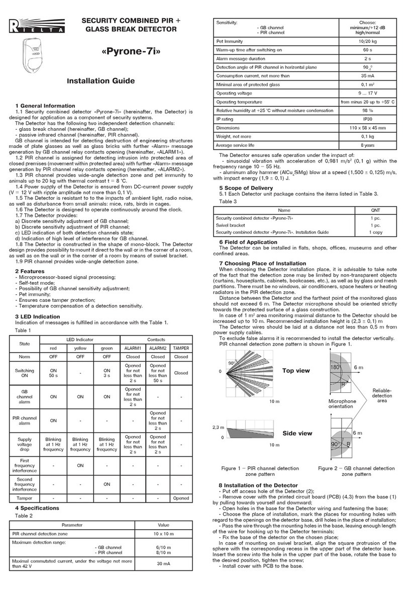
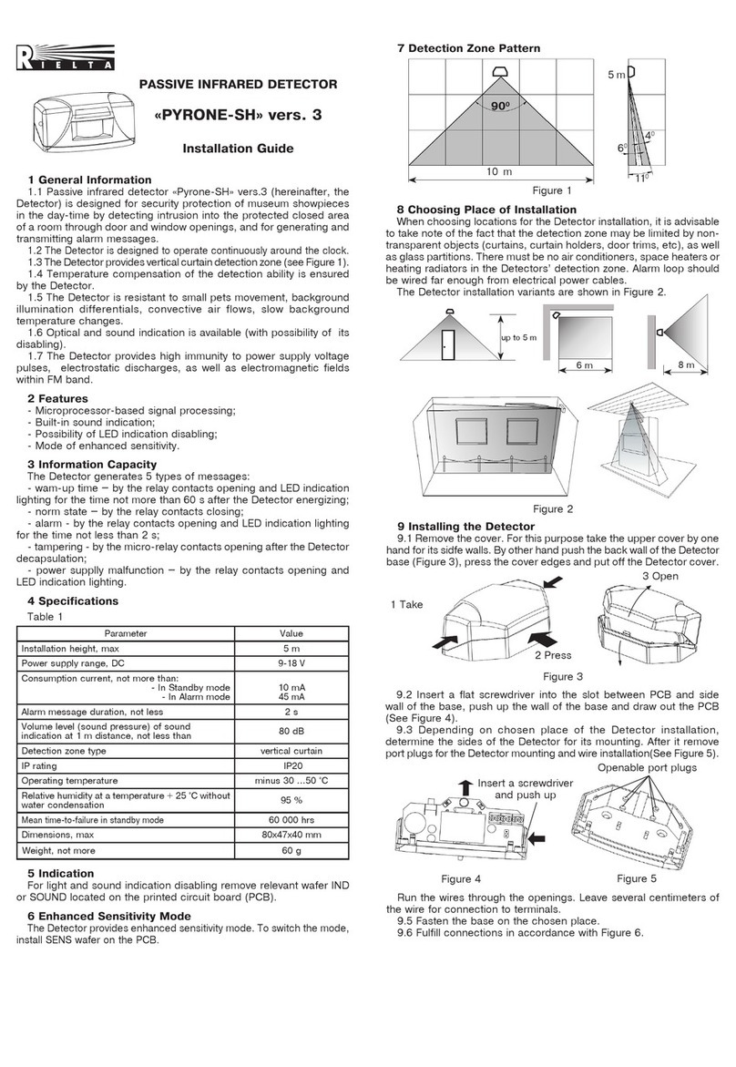
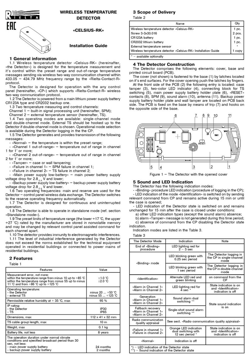
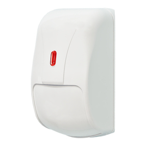
manuals.online logo
Brands
  1. Home
  2. •
  3. Brands
  4. •
  5. Rielta
  6. •
  7. Security Sensor
  8. •
  9. Rielta STZ-RK User manual

Rielta STZ-RK User manual

WIRELESS FLOOD
DETECTOR
«STZ-RK»ver. 1
1 Product Overview
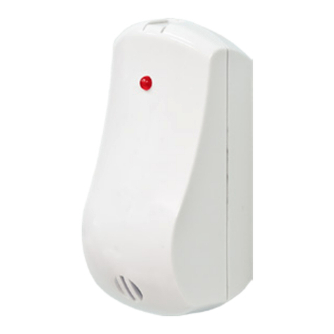
1.1 Wireless flood detector «STZ-RK» ver. 1 (hereinafter, the
Detector) is intended for detecting leaks of water from water-supply
pipelines or heating facilities and generating an alarm message
via a two-way communication by the «Rielta-Contact-R» protocol.
The Detector is intended to operate as a component of any control
panel (hereinafter, CP) supporting the wireless exchange protocol
«Rielta-Contact-R».
1.2 Water leaks control is ensured by measurement of an external
resistance between sensor terminals of the Detector.
1.3 Radio signals are exchanged within the 433.05 to 434.79 MHz
frequency range. The transmitter output power does not exceed
10 mW.
1.4 Two operating frequencies: main and reserve are used for the
wireless data exchange. The Detector switches over reserve operating
frequency automatically.
1.5 Radio exchange sessions are initiated by the Detector at a
preset frequency. The frequency settings are
10, 15, 30 sec,
1, 5,
10 min, chosen in the process of the binding procedure. The Detector
transmits alarm messages to the CP immediately.
1.6 The Detector power supply is provided by power supply batteries
placed inside it’s case: the main one and the backup one (CR2450).
1.7 The Detector state is displayed by two-color LED indicator.
1.8 The Detector generates and transmits the following messages
via a two-way communication:
- «Norm» – if the external resistance between sensor terminals value
is 200 kΩor more;
- «Alarm» – if the external resistance between sensor terminals
value is 100 kΩor less;
- «Tamper» – in the event of case tampering or the Detector removal
from the mounting surface;
- «Main Power Supply Low Battery» – under the main power supply
battery voltage drop below 2.2-0.2 V;
- «Backup Power Supply Low Battery» – under the backup power
supply battery voltage drop below 2.2-0.2 V.
1.9 The Detector is designed to operate continuously, around the
clock.
2 Features
Table 1
Parameter Value
Operating temperature, °C
minus 20 … +55
Permissible relative humidity at +25 °С without
moisture condensation up to, % 98
IP rating IP65
Dimensions, maximum, mm 65 x 55 x 20
Weight, maximum, kg 0.05
Average service life, not less, years 8
Operation time upon normal climate conditions* and
preset wireless signal exchange rate 30 sec and
more, months:
- from the main battery, not less:
- from the reserve battery, not less:
60
2
3 Scope of Delivery
Each Detector unit package contains the items listed in Table 2.
Table 2
Name
QNT.
Wireless flood detector «STZ-RK» ver. 1
Screw 3-3х30.016
CR2450 lithium power supply battery
Wireless flood detector «STZ-RK» ver. 1. Installation Guide
1 pc.
1 pc.
2 pcs.
1 copy
4 The Detector Design
In order to open the cover of the detector insert a screwdriver
tip into the notch and then press it down to move the latch (See
Figure 1).
Installation Guide
Figure 2 – The Detector Design
5 Indication
The Detector has the following indication modes:
- «Binding» procedure LED indication (procedure of logging in the CP);
- «Identification»indication mode –lights up by the relevant command
from CP and remains active during 15 min or until the case is opened;
- LED indication of the Detector state is activated after the Detector
cover is closed and remains active during 15 min under conditions:
- other LED indication types absence;
- alarm «Tamper» message is not generated during this time;
- absence of command from the CP disabling the Detector state
indication.
LED indicator modes are listed in the Table 3.
Table 3
The Detector State LED Indication Note
Binding procedure
finished
LED lighting red for
2 – 3 sec
«
Binding
»
mode LED blinking green The Detector logging in
the CP
«
Identification
»
Alternate LED red and
green alternate blinking
on command from the
CP
«
Alarm
»
Single-shot LED lights up
red for 4 sec
State indication is on
and
«
Identification
»
indication is off
Radio communication
quality appraising See sect.
«
Radio communication quality appraising
»
«Normal»
Indication is off
6 Binding with the CP
«Binding»mode is used for logging the Detector in the CP and service
information exchange.
6.1 Prepare the CP in accordance with CP reference guide.
6.2 Initially install the backup power supply battery to the holder
plate (4) on the PCB, thereupon install the main power supply battery
to the holder plate (2) (or remove the insulator if the battery is already
installed).
6.3 Periodical LED indicator blinking green is evidence of binding
process.
6.4 In case of mentioned above LED indication absence, short-circuit
«RESET» terminals for 2 – 3 sec.
6.5 The time limit for the binding process of the Detector is 70 sec.
To restart the binding procedure, short-circuit «RESET» terminals for
2 – 3 sec.
7 Communication Quality Appraising
7.1 To apprise the radio communication quality it is necessary to
act as follows:
- place initially backup and then main power supply batteries to the
correspondent holder plates;
а) Base b) PCB installed on the cover
1
7
2
3
4
6
5
5
RESET
MAIN
BACKUP
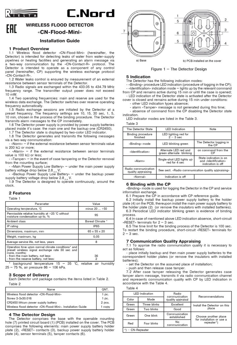
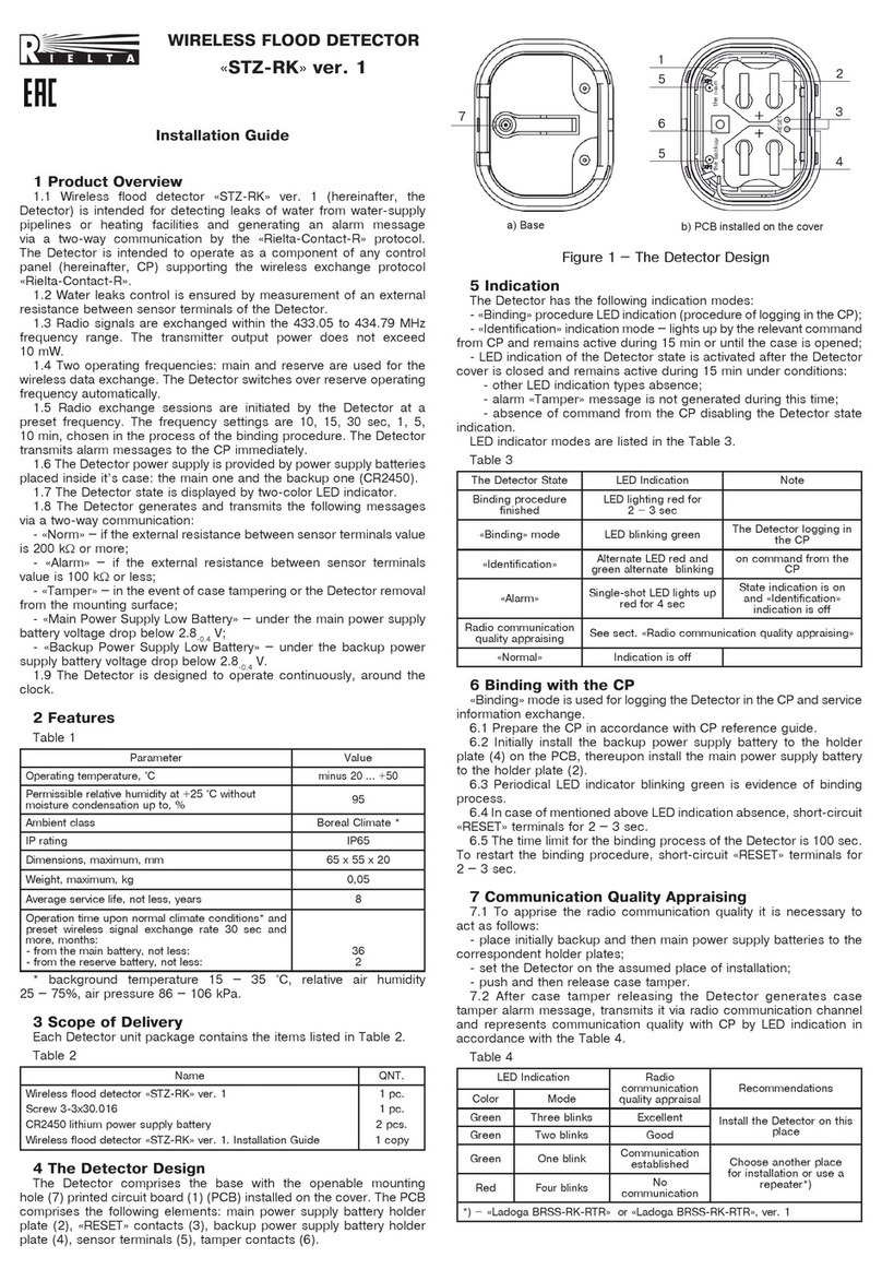
The Detector comprises the base with the openable mounting
hole (7) and the holes for the sensory terminals (8) printed circuit
board (1) (PCB) installed on the cover. The PCB comprises the
following elements: main power supply battery holder plate (2),
«RESET» contacts (3), backup power supply battery holder plate (4),
sensor terminals (5), tamper contacts (6).
Figure 1
Rev. 4 of 22.05.18
№00473
v.10.1
9 Storage and Transportation
9.1 The Detector in original package without power supply batteries
is resistant to:
а) transport jolting with the acceleration of 30 m/sec2with impact
frequency rate from 10 to 120 impacts/sec or 15000 impacts with the
same acceleration;
b) the ambient temperature from minus 50 … +50 °С;
c) relative air humidity (95 ± 3) % at the ambient temperature +35 °С.
9.2 The Detectors in original package may be transported by any
transport facility in closed vehicles over any distances in compliance with
the existing shipping rules concerning the respective means of transport.
9.3 After transportation under the conditions different to exploitation
conditions, the Detector shall be ready to operate after a maximum of
six hours.
10 Manufacturer’s Guarantees
10.1 «RIELTA» JSC guarantees conformity of the Detector to the
requirements of technical conditions provided the transportation,
storage, installation and operation conditions are observed.
10.2 The guaranteed shelf life of the Detector is 39 months since
the date of manufacture.
10.3 The guaranteed useful life is 36 months since the day of putting
into operation.
10.4 The Detectors that are found non-conforming to the requirements
of technical conditions shall be repaired by the manufacturer, provided
the installation and operation rules have been complied.
Note – Warranty obligations are not applied to power supply battery.
11 Packing Certificate
Wireless flood detector «STZ-RK» ver. 1 has been manufactured in
compliance with the active technical documentation and classified as
fit for operation and packed by «RIELTA» JSC.
Packing date _______________________________
month, year
Made in Russia
«RIELTA» JSC, www.rielta.com,
Chapaeva Str. 17, Saint Petersburg, Russia, 197101, [email protected],
Tel./fax. +7 (812) 233-0302, 703-1360,
Technical support, tel. +7 (812) 233-29-53, 703-13-57, [email protected].
- set the Detector on the assumed place of installation;
- push and then release case tamper.
7.2 After case tamper releasing the Detector generates case
tamper alarm message, transmits it via radio communication channel
and represents communication quality with CP by LED indication in
accordance with the Table 4.
Table 4
LED Indication Radio
communication
quality appraisal
Recommendations
Color Mode
Green Three blinks Excellent Install the Detector on this
place
Green Two blinks Good
Green One blink Communication
established Choose another place
for installation or use a
repeater*)
Red
Four blinks
No communication
*) – «Ladoga-RK» system repeater
8 Installation
8.1 Install the Detector in the place, where communication quality is
apprised as «good» or «Excellent» (See Table 4).
8.2 Fasten the base to the mounting surface by means of double-sided
mounting tape. To ensure the Detector secure mounting act as follows:
- make sure, that the mounting surface is flat, dry and clean;
- remove protective film from the mounting tape working surface;
- press the Detector tightly to the mounting surface and hold it for
2 – 3 sec;
For the wall-tamper monitoring, the second screw should be fastened
in an openable hole (7) (See Figure 3).
Figure 3
8.3 Install the cover with PCB on the base (See Figure 4). The sensory
terminals (5) should fall into the hole (8).
Figure 4
Attention! If the CP is planned to be switched off for a long time,
de-energize the Detector to ensure the battery resource economy.

Other Rielta Security Sensor manuals

Rielta FOTON-17 User manual

Rielta

Rielta FOTON-17 User manual

Rielta FOTON-21 User manual

Rielta

Rielta FOTON-21 User manual

Rielta FOTON-15A User manual

Rielta

Rielta FOTON-15A User manual

Rielta PYRONE-8B-RK User manual

Rielta

Rielta PYRONE-8B-RK User manual

Rielta Pyrone-7 User manual

Rielta

Rielta Pyrone-7 User manual

Rielta C.Nord CN-Glass User manual

Rielta

Rielta C.Nord CN-Glass User manual

Rielta FOTON-SH User manual

Rielta

Rielta FOTON-SH User manual

Rielta SH-V User manual

Rielta

Rielta SH-V User manual

Rielta STZ-RK User manual

Rielta

Rielta STZ-RK User manual

Rielta chrana ORLAN-SH User manual

Rielta

Rielta chrana ORLAN-SH User manual

Rielta ZVON-1 User manual

Rielta

Rielta ZVON-1 User manual

Rielta ORLAN-2 User manual

Rielta

Rielta ORLAN-2 User manual

Rielta Ladoga MK-RK version 2 User manual

Rielta

Rielta Ladoga MK-RK version 2 User manual

Rielta PYRONE-SH2-RK User manual

Rielta

Rielta PYRONE-SH2-RK User manual

Rielta Ochrana FOTON-19RK User manual

Rielta

Rielta Ochrana FOTON-19RK User manual

Rielta STZ-RK User manual

Rielta

Rielta STZ-RK User manual

Rielta Ladoga MK-RK User manual

Rielta

Rielta Ladoga MK-RK User manual

Rielta FOTON-16B User manual

Rielta

Rielta FOTON-16B User manual

Rielta ZVON-1 User manual

Rielta

Rielta ZVON-1 User manual

Rielta OCHRANA Ladoga MK-RK User manual

Rielta

Rielta OCHRANA Ladoga MK-RK User manual

Rielta PYRONE-8B-RK User manual

Rielta

Rielta PYRONE-8B-RK User manual

Rielta SH-V-10 User manual

Rielta

Rielta SH-V-10 User manual

Rielta PYRONE-SH2-RK User manual

Rielta

Rielta PYRONE-SH2-RK User manual

Rielta FOTON-10M User manual

Rielta

Rielta FOTON-10M User manual

Popular Security Sensor manuals by other brands

HDE GREENLEE TAG-200X instruction manual

HDE

HDE GREENLEE TAG-200X instruction manual

eufy Security Smart Buoy user manual

eufy Security

eufy Security Smart Buoy user manual

iMSENS iMS M4-4 manual

iMSENS

iMSENS iMS M4-4 manual

Bosch PMD 7 Original instructions

Bosch

Bosch PMD 7 Original instructions

Omron F3SL instruction manual

Omron

Omron F3SL instruction manual

OzSpy MEQC3506 quick start guide

OzSpy

OzSpy MEQC3506 quick start guide

Teknim TFD-1260A Installation & user manual

Teknim

Teknim TFD-1260A Installation & user manual

MAXIMUM Security VIP Pro Installation & operating guide

MAXIMUM Security

MAXIMUM Security VIP Pro Installation & operating guide

Atsumi Electric NR30TD installation instructions

Atsumi Electric

Atsumi Electric NR30TD installation instructions

Conrad RSL Series operating instructions

Conrad

Conrad RSL Series operating instructions

GE 45132 user manual

GE

GE 45132 user manual

Vogel QZ80 user manual

Vogel

Vogel QZ80 user manual

LST UVIR2 16591 Specifications

LST

LST UVIR2 16591 Specifications

GTV CR-9Mini manual

GTV

GTV CR-9Mini manual

MSA FlameGard 5 UV/IR-E quick start guide

MSA

MSA FlameGard 5 UV/IR-E quick start guide

PNI A005 user manual

PNI

PNI A005 user manual

Chacon 34272 user manual

Chacon

Chacon 34272 user manual

Mannesmann 99980 instruction manual

Mannesmann

Mannesmann 99980 instruction manual

manuals.online logo
manuals.online logoBrands
  • About & Mission
  • Contact us
  • Privacy Policy
  • Terms and Conditions

Copyright 2025 Manuals.Online. All Rights Reserved.