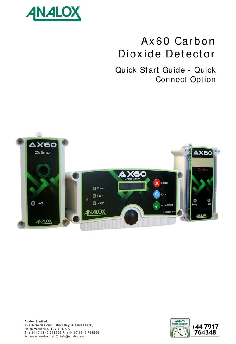
ANALOX Ax60 User manual

Analox Limited
15 Ellerbeck Court, Stokesley Business Park,
North Yorkshire, TS9 5PT, UK
T: +44 (0)1642 711400 F: +44 (0)1642 713900
W: www.analox.net E: info@analox.net
Ax60 Carbon
Dioxide Detector
Quick Start Guide - Hard
Wired Option

Ax60 Carbon Dioxide Detector
Quick Start Guide - Hard Wired Option
Document ref: P0159-802-03 September 2015 Page 2 of 16
Safety information
Warnings are used in this Quick Start Guide to indicate potentially hazardous situations
which could result in serious injury or death. Cautions are used to indicate potentially
hazardous situations that could result in equipment damage or loss of data. Notes are
used to provide information that is important but not hazard related.
WARNING: READ THE SAFETY INFORMATION IN THIS QUICK START GUIDE
BEFORE INSTALLING OR USING THE Ax60.
WARNING: DO NOT TEST THE CO2ALARM WHEN IT IS CLOSE TO THE EARS. IT
HAS A HIGH VOLUME SOUNDER WITH A SOUND LEVEL OF 88
DECIBELS AT A DISTANCE OF 3 METRES.
WARNING: DO NOT TEST THE CO2ALARM WHEN IT IS CLOSE TO THE EYES. IT
HAS A HIGH VISIBILITY STROBE LIGHT WITH A LUMINOUS
INTENSITY OF 100 CANDELA.
WARNING: ENSURE YOU PERFORM A RISK ASSESSMENT BEFORE INSTALLING
CO
2SENSORS AND CO2ALARMS. IDENTIFY POTENTIAL SOURCES
OFCO
2LEAKS AND AREAS OF HUMAN OCCUPATION. DO NOT USE
ASINGLECO
2SENSOR TO COVER MORE THAN 80M3. USE
ADDITIONAL CO2SENSORS IF AN AREA HAS A COMPLEX SHAPE,
PHYSICAL OBSTACLES, POOR VENTILATION OR ZONES WHERE
CO
2MAY COLLECT.
WARNING: INSTALL CO2SENSORS AT A HEIGHT OF 12–18" (305–457MM)
ABOVE FLOOR LEVEL. THIS IS BECAUSE CO2IS HEAVIER THAN
AIR AND MAY COLLECT AT A LOW LEVEL.
WARNING: DO NOT OPEN THE CENTRAL DISPLAY, CO2SENSOR OR CO2ALARM
IF THEY ARE CONNECTED TO THE POWER SUPPLY. DISCONNECT
AND ISOLATE THEM FROM LIVE HAZARDOUS VOLTAGE.

Ax60 Carbon Dioxide Detector
Quick Start Guide - Hard Wired Option
Document ref: P0159-802-03 September 2015 Page 3 of 16
Contents
1Introduction .......................................................... 4
2Installation............................................................ 6
3Cabling .................................................................. 7
4Connection............................................................. 8
5Operation............................................................. 12
6Configuration....................................................... 16

Ax60 Carbon Dioxide Detector
Quick Start Guide - Hard Wired Option
Document ref: P0159-802-03 September 2015 Page 4 of 16
1Introduction
This Quick Start Guide explains how to install and use the Ax60 Hard Wired option. For
more information on operation and maintenance, refer to the Ax60 User Manual P0159-
800. For more information on servicing and calibration, refer to the Ax60 Service
Manual P0159-803. These are available to download from http://www.analox.net/
The standard Ax60 is available as either a Hard Wired or a Quick Connect option.
This choice must be made when placing the order. Hard Wired systems are intended to
be integrated with the building fabric. Quick Connect systems are pre-wired with Cat5e
cables fitted with colour-coded RJ45 connectors for easy installation. Both require the
installer to connect the power supply unit and optional beacon to the Central Display.
The Ax60K Kiosk option is a more compact solution that offers the convenience of
Quick Connect cabling and does not require a Central Display unit.
1.1 Purpose of the Ax60
The Ax60 is a life-safety device that measures the amount of carbon dioxide (CO2) in
the air. If a CO2Sensor detects a potentially dangerous level of CO2it triggers an alarm
on the Central Display which is then announced by the CO2Alarms.
The Central Display provides real-time gas readings from each CO2Sensor together
with any alarm or fault indications. The Central Display can be easily interrogated to
show detailed information on the CO2Sensors and CO2Alarms that are connected to it.
An Ax60 Central Display can be connected to a maximum of four CO2Sensors and a
maximum of eight CO2Alarms. To extend the alarm functions, an optional beacon is
available and two alarm-relay outputs are provided for integration with other systems.
The Central Display is usually installed in a principal location (e.g. a Manager‘s office)
and connected to one or more CO2Sensors fitted in remote areas such as store rooms
or service corridors.
The CO2Sensors send alarm signals to one or more CO2Alarm units in locations where
they can be observed by management or crew. The Central Display monitors the CO2
Sensors and displays their current status and CO2measurements.
1.2 The dangers of CO2
Fresh air contains a safe level of 0.04% or 400ppm (parts per million) CO2. An increase
to 1.5% (15,000ppm) causes drowsiness, headache and increased breathing. A level of
3% (30,000ppm) causes dizziness. 10% (100,000ppm) will cause unconsciousness and
eventually death. CO2is odourless and colourless and is not detected by human senses.
There is a danger to health wherever pressurised or concentrated CO2is stored or used.
1.3 Ax60 alarm settings
The Ax60 has three alarm settings which are factory set:
Time-weighted average (TWA) alarm
–triggered by 5000 ppm (0.5%) CO2over the previous 8 hours. TWA alarm is
displayed on the CO2Sensor by a flashing red indicator LED and internal buzzer
Low alarm
–triggered by 15,000ppm (1.5%) CO2. Low alarm is announced by both the CO2
Sensor (internal buzzer) and the CO2Alarm (high-visibility strobe)
High alarm
–triggered by 30,000ppm (3%) CO2. High alarm is announced by both the CO2
Sensor (internal buzzer) and the CO2Alarm (strobe light and sounder)

Ax60 Carbon Dioxide Detector
Quick Start Guide - Hard Wired Option
Document ref: P0159-802-03 September 2015 Page 5 of 16
1.4 Package contents
Ax60 Carbon
Dioxide
Detector
(contents may
vary depending
on the package
ordered)
1 x Central Display
1 x power supply unit (PSU), either hard-wired type or plug-in type
depending on the package ordered
1 x PSU securing strip (for plug-in type PSU only)
1 to 4 x CO2Sensors (depending on the package ordered)
1 to 8 x CO2Alarms (depending on the package ordered)
1 x high-visibility optional beacon (if ordered)
Self-adhesive foam gaskets for use in rear-entry cable installations
1 x hazard labels, information labels, templates and Quick Start Guide
Consumables
(depending on
the package)
Cat5e UTP 24AWG PVC cable, length to suit installation
M13 cable glands 5—7mm (nylon), quantity to suit installation
Wall plugs and screws (fixing kits), quantity to suit installation
Tools (to be
provided by
installer)
PZ1 Pozi screwdriver; 3mm flat blade screwdriver
Cat5e cable jacket stripper; 24AWG wire stripper
Drill and drill bits for wall plugs; spirit level, tape measure, ruler
Small hammer, centre punch and pliers for removing knockouts

Ax60 Carbon Dioxide Detector
Quick Start Guide - Hard Wired Option
Document ref: P0159-802-03 September 2015 Page 6 of 16
2Installation
2.1 General
CAUTION: SOME ENCLOSURES ARE SUPPLIED UNFASTENED WITH FIXING SCREWS
LOOSE. DO NOT OVER-TIGHTEN THE SCREWS WHEN FASTENING THE LIDS ON.
2.1.1 Central Display
Retain the clear protective film on the fascia until
the installation is complete. Using the supplied
paper template mark out the wall-fixing position
ensuring the Central Display is level. If you are
installing cable through the rear of the enclosure,
remove the knockout then fit a foam gasket over
its aperture to provide a seal against ingress
CAUTION: TO PREVENT DAMAGE TO THE
FASCIA AND PRINTED CIRCUIT BOARD
(PCB), REMOVE THEM FROM THE ENCLO-
SURE BEFORE REMOVING KNOCKOUT.
Drill holes in the wall then fit wall plugs/dowels.
Fasten the lid of the enclosure to the base then
fix the Central Display in position. Install the
cables in position and cut them to length.
Removing a knockout
To remove the knockout, place the enclosure
face down on a solid, non-slip surface. Tap the
knockout firmly using a hammer and punch. Use
pliers to remove sharp edges from the aperture.
2.1.2 CO2Sensor
Retain the clear protective film on the fascia until
the installation is complete. Using the supplied
paper template mark out the wall-fixing position
ensuring the CO2Sensor is level. (If installing a
cable through the rear, remove the knockout.)
WARNING: CARBON DIOXIDE GAS (CO2)
IS HEAVIER THAN AIR AND SHOULD BE
MONITORED FROM A LOW HEIGHT. YOU
SHOULD THEREFORE INSTALL THE CO2
SENSOR AT A HEIGHT OF 12–18" (305–
457MM) ABOVE THE FLOOR LEVEL.
Drill holes in wall, install wall plugs/dowels then
fit the CO2Sensor. Install the cables in position
and cut them to length.
2.1.3 CO2Alarm
WARNING: LOCATE THE CO2ALARM SO
AS TO PROVIDE COVERAGE FOR ACCESS
AND EGRESS POINTS AND BUSY AREAS.
Retain the clear protective film on the fascia until
the installation is complete. Using the supplied
paper template mark out the wall-fixing position
ensuring the CO2Alarm is level. (If installing a
cable through the rear, remove the knockout.)
Drill holes in wall, install wall plugs/dowels then
fit the CO2Sensor Install the cables in position
and cut them to length.

Ax60 Carbon Dioxide Detector
Quick Start Guide - Hard Wired Option
Document ref: P0159-802-03 September 2015 Page 7 of 16
3Cabling
The diagram below illustrates a typical cabling arrangement for the Hard Wired option.
The recommended cable for the Ax60 is Cat5e UTP 24AWG PVC (see example below).
Cable type Wire colour Abbreviation
Cat5e, UTP, Orange ORG
24AWG, PVC Orange / white ORG/WHT
Brown BRN
Brown / white BRN/WHT
Green / white GRN/WHT
Green GRN
Blue / white BLU/WHT
Blue BLU
If you install cables through walls, remove the knockout and fit a foam gasket to maintain ingress
protection (see below left). If you install cables along wall surfaces, fit cable glands (below right).
CAUTION: ENSURE THAT THE MAXIMUM CABLE LENGTH BETWEEN THE CENTRAL
DISPLAY AND THE FINAL SENSOR IS NOT MORE THAN 100 METRES.

Ax60 Carbon Dioxide Detector
Quick Start Guide - Hard Wired Option
Document ref: P0159-802-03 September 2015 Page 8 of 16
4Connection
4.1 Sensors and Alarms
The recommended cable arrangement for connecting the CO2Sensors and CO2Alarms
is shown below. For the purposes of this example the enclosures have been removed
and the cables have been shortened for convenience. The Central Display is not shown.
1) Two CO2Sensors connected
together in a daisy-chain 2) Two CO2Alarms connected
together in a daisy-chain
4.2 Central Display
CO2Sensor Beacon
Power Relay 2
Relay 1
(See
section
4.2.1)
(See
section
4.2.3)
(See
section
4.2.2)
NOTE: REFER TO THE Ax60
SERVICE MANUAL FOR
DETAILS ON CONNECTING
RELAYS 1 & 2.

Ax60 Carbon Dioxide Detector
Quick Start Guide - Hard Wired Option
Document ref: P0159-802-03 September 2015 Page 9 of 16
4.2.1 Central Display to CO2Sensor
Cable connections from left to right:
GRN/WHT (RS485 A, single cable)
GRN (RS485 B, single cable)
BRN & BRN/WHT (supply negative, two
cables twisted together)
ORG & ORG/WHT (supply positive, two cables
twisted together)
NOTE: THE BLUE AND BLUE/WHITE
CABLES CAN BE REMOVED (CUT OFF).
4.2.2 Central Display to power supply unit (PSU)
Two types of PSU are available, to suit different types of installation. One is a plug-in
type, the other is a hard-wired type for connection to a fixed power supply (fused spur).
WARNING: THE HARD-WIRED PSU SHOULD BE CONNECTED TO A 3A FUSED SPUR.
PSU, plug-in type
(supplied with plug
for specific country)
PSU, hard-wired type
(for connection to a
fixed power supply)
The plug-in PSU is supplied with a securing
strip, wall plugs and screws to reduce risk
of accidental disconnection or tampering
WARNING: THE POSITIVE AND NEGATIVE POWER CABLES ARE IDENTIFIED
DIFFERENTLY DEPENDING ON THE TYPE OF PSU SUPPLIED. READ
THE INSTRUCTIONS BELOW BEFORE INSTALLING THE PSU CABLE:
Plug-in type PSU cable identification
Black with stripe: Positive (24V)
Black with print: Negative (0V)
Hard wired type PSU cable identification
Black with stripe: Negative (0V)
Black with print: Positive (24V)
4.2.3 Central Display to optional beacon (labelled ‘STROBE’ on the PCB)
Cable connections from left to right:
BLK (0V supply to optional beacon)
RED (24V supply to optional beacon)
CAUTION: CABLE COLOURS BETWEEN
THE CENTRAL DISPLAY AND BEACON
MAY VARY. THE INSTALLER MAY USE
CAT5E CABLE IF PREFERRED, PROVI-
DING TWISTED PAIRS ARE USED.

Ax60 Carbon Dioxide Detector
Quick Start Guide - Hard Wired Option
Document ref: P0159-802-03 September 2015 Page 10 of 16
4.3 CO2Sensor
NOTE: THE FOUR SCREW TERMINALS AT
THE TOP ARE FOR CONNECTING THE
CO2SENSOR TO THE CENTRAL DISPLAY.
ON THE PCB THESE ARE LABELLED
‘CENTRAL UNIT’ (SEE 4.3.1 BELOW).
NOTE: THE SIX SCREW TERMINALS AT
THE BOTTOM ARE FOR CONNECTING
THE CO2SENSOR TO THE CO2ALARM.
ON THE PCB THESE ARE LABELLED
‘STROBE/ SOUNDER’ (SEE 4.3.2).
4.3.1 CO2Sensor to Central Display
Cable connections from top to bottom:
ORG & ORG/WHT (supply positive, two cables
twisted together)
BRN & BRN/WHT (supply negative, two cables
twisted together)
GRN (RS485 B, single cable)
GRN/WHT (RS485 A, single cable)
NOTE: THE BLUE AND BLUE/WHITE
CABLES CAN BE REMOVED (CUT OFF).
NOTE: SENSOR 2 CABLE SHOULD BE DAISY-CHAINED FROM SENSOR 1 TERMINALS.
4.3.2 CO2Sensor to CO2Alarm
Cable connections from top to bottom:
ORG & ORG/WHT (supply positive, two cables
twisted together)
BRN & BRN/WHT (supply negative, two cables
twisted together)
GRN/WHT (alarm strobe driver, single cable)
GRN (alarm sounder driver, single cable)
BLU/WHT (fault LED driver, single cable)
NOTE: THE BLUE CABLE CAN BE
REMOVED (CUT OFF).
4.3.3 CO2Sensor jumper locations
Each CO2Sensor PCB contains a SENSOR
LOCATION selector with 4 jumper links. One
jumper link is provided with each sensor - an
example is shown here on the right:
By default this jumper link is fitted in SENSOR
LOCATION 1.
Each CO2Sensor must be given a different
SENSOR LOCATION by moving its jumper link.
For example, in a 2-sensor system, one
sensor‘s jumper link must be set to SENSOR
LOCATION 1, and the other sensor‘s jumper
link must be set to SENSOR LOCATION 2.

Ax60 Carbon Dioxide Detector
Quick Start Guide - Hard Wired Option
Document ref: P0159-802-03 September 2015 Page 11 of 16
4.4 CO2Alarm
NOTE: ALL CO2ALARMS ASSOCIATED
WITH A COMMON SENSOR SHOULD BE
CONNECTED VIA A DAISY-CHAIN
CABLE ARRANGEMENT. FOR EXAMPLE,
IF SENSOR 1 IS REQUIRED TO DRIVE
TWO ALARMS, ONE CABLE SHOULD BE
CONNECTED BETWEEN CO2SENSOR 1
AND CO2ALARM 1; AND ONE CABLE
SHOULD BE CONNECTED BETWEEN
CO2ALARM 1 AND CO2ALARM 2 (SEE
THE EXAMPLE IN SECTION 4.1).
4.4.1 CO2Alarm to CO2Sensor
Cable connections from top to bottom:
BLU/WHT (fault LED driver, single cable)
GRN (alarm sounder driver, single cable)
GRN/WHT (alarm strobe driver, single cable)
BRN & BRN/WHT (supply negative, two cables
twisted together)
ORG & ORG/WHT (supply positive, two cables
twisted together)
NOTE: THE BLUE CABLE CAN BE
REMOVED (CUT OFF).
4.5 Optional beacon
CAUTION: ENSURE THE TERMINAL BLOCK ON THE UNDERSIDE OF THE BEACON IS
FITTED TO THE 0V AND THE 24V PINS. THEN ENSURE THAT THE POWER
CABLES ARE CONNECTED TO THE 0V AND THE 24V SCREW TERMINALS.
Black cable: 0V supply to Central Display
Red cable: 24V supply to Central Display (left) The beacon terminal block. Ensure this
is fitted on the 0V and 24V terminals (right)
4.5.1 Beacon locking mechanism
Note that the beacon has a locking mechanism to discourage tampering. To lock the
beacon onto its base, locate the spigots then twist the beacon clockwise. To unlock the
beacon, prise open the locking clip as shown below and twist the beacon anti-clockwise.

Ax60 Carbon Dioxide Detector
Quick Start Guide - Hard Wired Option
Document ref: P0159-802-03 September 2015 Page 12 of 16
5Operation
5.1 Using the Central Display
The Ax60 Central Display supplies power to the CO2Sensors, CO2Alarms and beacon,
and is used to configure all system functions. The three buttons on the front panel allow
access to the operating software. The three indicator lamps display the system status.
5.1.1 Indicators and buzzer
Power Green indicator lamp. Flashes once per second to indicate that power is on
and the unit is operating.
Fault Yellow indicator lamp. Flashes once per second if there is a fault. Accomp-
anied by a fault message (FLT or COMMS FAULT) and buzzer once per second.
Alarm Red indicator lamp. Flashes rapidly when alarm is triggered. Accompanied
by an alarm message (either AL1 or CO2) and rapid operation of the buzzer.
Buzzer (apertu-
re on the left of
the indicators)
Buzzer sounds briefly each time a button is pressed. Sounds continuously
for five seconds when using the TESTING ALARMS function. It sounds rapidly
on and off when an alarm is triggered, or once per second for a fault.
5.1.2 Control buttons
Cancel To use this button, press it firmly then release it quickly. The buzzer will
sound briefly.
Press this button to cancel a menu option or return to the previous screen.
Cycle To use this button, press it firmly then release it quickly. The buzzer will
sound briefly.
Press this button to go to the next option on the screen.
Accept/Test To use this button press firmly then release quickly; the buzzer will sound.
A short press is used to select an option or mute an alarm/fault.
A longer press is used to remove the alarm, by holding the button until
the buzzer sounds (alarms can not be removed until the CO2level drops).
Press firmly and hold down for a few seconds to test the alarms.

Ax60 Carbon Dioxide Detector
Quick Start Guide - Hard Wired Option
Document ref: P0159-802-03 September 2015 Page 13 of 16
5.2 CO2Sensor
The CO2Sensor has a green Power indicator on the bottom left-hand part of the fascia.
This is used to indicate the following conditions:
Power indicator
Under normal conditions the Power indicator
flashes once per second to indicate that the
power is on and the unit is operating.
NOTE: THE CO2SENSOR RECEIVES ITS
POWER FROM THE CENTRAL DISPLAY,
VIA THE CONNECTING CAT5E CABLE.
If the Power indicator is off, this means the CO2
Sensor is either not receiving power from the
Central Display, or the CO2Sensor has a fault.
NOTE: CHECK THE CENTRAL DISPLAY;
IT MAY BE SHOWING A FAULT CODE.
If the Power indicator lamp is on continuously,
this means that there is potentially a more
serious CO2Sensor fault.
NOTE: CHECK THE CENTRAL DISPLAY;
IT MAY BE SHOWING A FAULT CODE.
If a CO2Sensor is in fault, any CO2Alarms
connected to it will also display a fault status
(their yellow Fault indicator LEDs will flash).
NOTE: FAULT CODES ARE DESCRIBED
IN DETAIL IN THE SERVICE MANUAL.
5.3 CO2Alarm
The CO2Alarm has a green Power indicator and a yellow Fault indicator on the bottom
part of the fascia. These are used to indicate the following conditions:
Power indicator
Under normal conditions the Power indicator is
continuously on (not flashing) to indicate that
the power is on and the unit is operating.
NOTE: THE CO2ALARM RECEIVES ITS
POWER FROM THE CO2SENSOR, VIA
THE CONNECTING CAT5E CABLE.
If the Power indicator lamp is off this means
that the CO2Alarm is not receiving power.
Fault indicator
Under normal conditions the yellow Fault
indicator is off.
NOTE: THE FAULT INDICATOR IS NOT
USED TO SHOW FAULTS ON THE CO2
ALARM, IT IS USED TO SHOW FAULTS
ON THE SENSOR CONNECTED TO IT.
If the Fault indicator is flashing it means the
CO2Sensor connected to the Alarm is in fault.
NOTE: FAULT CODES ARE SHOWN ON
THE CENTRAL DISPLAY. FOR FURTHER
DETAILS SEE THE SERVICE MANUAL.

Ax60 Carbon Dioxide Detector
Quick Start Guide - Hard Wired Option
Document ref: P0159-802-03 September 2015 Page 14 of 16
5.4 Powering up
5.4.1 Power-on-self-test (POST)
When you switch on the power supply the Ax60 performs a power-on-self-test (POST)
which takes about 30 seconds. The results of the POST are displayed on the screen:
Operator input Software response Central Display text Optional display text
Switch on power
supply to Ax60 Displays vendor name
(default is Analox Ltd)
Vendor name may vary
No further operator input is required. The power-on-self-test is an automatic process...
Performs a checksum
configuration check
Performs a software
validation check
Checks the CO2Sensor(s)
have been calibrated
This displays if no sensors
have been configured
Confirms top line of LCD
OK, no pixels are missing
Confirms bottom line of
LCD OK, no pixels missing
Confirms buzzer is off and
green LED switches on
Confirms green LED is off
and yellow switches on
Confirms yellow LED is off
and red switches on
Confirms red LED is off
and buzzer switches on
Displays current version
of the software and the
buzzer switches off
Displays unique serial
number of the unit

Ax60 Carbon Dioxide Detector
Quick Start Guide - Hard Wired Option
Document ref: P0159-802-03 September 2015 Page 15 of 16
Operator input Software response Central Display text Optional display text
Wait for CO2Sen-
sors to warm up...
This screen may display
for a few seconds to show
CO2Sensor warm-up
status. It is for
information only. It
requires no operator input
CAUTION: EACH CO2SENSOR MUST HAVE ITS JUMPER SET TO A DIFFERENT
LOCATION (E.G. SENSOR 1 = LOCATION 1; SENSOR 2 = LOCATION
2), OTHERWISE THE CENTRAL DISPLAY WILL ANNOUNCE A FAULT.
REFER TO SECTION 6.1 FOR JUMPER SETTINGS INFORMATION.
Wait for system
status screen... Displays system status
screen. Each CO2Sensor
is represented by ‘OK’ in
the top line. For example,
a system with two CO2
Sensors displays >OK OK.
The ‘>’ character identifies
which CO2Sensor is
highlighted (CO2Sensor 1
is highlighted by default)
The CO2concentration is
by default displayed in
ppm (parts per million).
The example shown here
displays 450 PPM, which
is equal to 0.045%
NOTE: THE SYSTEM
STATUS SCREEN
DISPLAYS UP TO 4
CO2SENSORS. A
SPARE CO2SENSOR
LOCATION
DISPLAYS AS ‘---’
The bottom line displays
the concentration of CO2
measured at the Sensor
Press Cycle Displays CO2Sensor 2
details (if installed) and
the current level of CO2
In this example, CO2
Sensor 2 is not installed
Press Cycle Displays CO2Sensor 3
details (if installed) and
the current level of CO2
In this example, CO2
Sensor 3 is not installed
Press Cycle Displays CO2Sensor 4
details (if installed) and
the current level of CO2
In this example, CO2
Sensor 4 is not installed
Press Cycle Redisplays the system
status screen

Ax60 Carbon Dioxide Detector
Quick Start Guide - Hard Wired Option
Document ref: P0159-802-03 September 2015 Page 16 of 16
6Configuration
6.1 Hardware setting
The CO2Sensor has a hardware setting that is factory configured for a system with only
one Sensor. If a system includes two, three, or four Sensors then the hardware must be
reconfigured by moving a jumper link ( ) in each Sensor installed in the system.
WARNING: DISCONNECT AND ISOLATE THE Ax60 SYSTEM FROM THE MAINS
POWER SUPPLY BEFORE OPENING THE CO2SENSOR ENCLOSURES.
To access the jumper link, open the CO2Sensor enclosure. The printed circuit board
(PCB) has a SENSOR LOCATION selector, with one link already installed in LOCATION 1.
For a system with only one CO2Sensor, the
j
umper link should be retained in LOCATION 1.
For a system with two CO2Sensors, the first
Sensor’s jumper link should be in LOCATION 1
and the second Sensor’s link in LOCATION 2.
For a system with three CO2Sensors, the
first Sensor’s link should be in LOCATION 1, the
second Sensor’s link in LOCATION 2 and the
third Sensor’s link should be in LOCATION 3.
For a system with four CO2Sensors, the first
Sensor’s jumper link should be in LOCATION 1,
the second Sensor’s link in LOCATION 2, the
third Sensor’s link in LOCATION 3 and the fourth
Sensor’s link should be in LOCATION 4.
6.2 Software setting
The Central Display software is factory configured for a system that has two Sensors. If
the system includes one, three, or four Sensors, the software must be reconfigured.
This is done by using the Top-level Menu, Configuration, Attached snsrs option. To enter
the Top-level menu, press and hold down Cancel + Cycle for at least six seconds. Then
press the Cycle button four times to display the Top-level menu, Configuration option.
NOTE: THE CENTRAL DISPLAY SOFTWARE IS FACTORY SET FOR TWO SENSORS.
Menu option Operator input Menu sub-option Functional description
Press Accept/Test to
go to Config. Menu
Attached snsrs
Press Accept/Test to
go to Num of
sensors?
The screen displays the
number of CO2Sensors
(default number is ‘>2’)
Press Cycle to choose
another number or
press Accept/Test
The screen displays a tick
to confirm the number of
sensors is now configured
Press Cancel to return to Config. Menu, Attached snsrs
Other manuals for Ax60
1
Table of contents
Other ANALOX Security Sensor manuals
Popular Security Sensor manuals by other brands

i4Technology
i4Technology BugHunter Professional BH-03 Expert Operation manual

SOMFY
SOMFY 5137725A000 installation instructions

ENFORCER
ENFORCER E-964-S50TB manual

ASO Safety Solutions
ASO Safety Solutions GE F-series manual

Bosch
Bosch ISC-PDL1-W18H installation instructions

Johnson Controls
Johnson Controls PG9200AX user manual

Pilz
Pilz PSEN ma1.3a-27 VA operating manual

Inficon
Inficon HLD6000 Original operating instructions

mySmart
mySmart EBDHS-DD-LT30 Product guide

Tractel
Tractel blocfor AES Series Operating and maintenance instructions

NA-DE
NA-DE 10901 instruction manual

Mustang Survival
Mustang Survival ELITE INFLATABLE PFD MD5153 owner's manual