Analytical Industries AII-2000 Palm O2 User manual

2855 Metropolitan Place, Pomona, CA 91767 USA ♦Tel: 909-392-6900, Fax: 909-392-3665, www.aii1.com, email: sales-medical@aii1.com Rev 6/11
Easyuserinterface...onetouchcontrols
Simpletouse...accurate reliable results
Onetouchcalibration...100%O2orair
Longbatterylife...13,000hrsofcontinuoususe
Advancedsensortechnology
Stateoftheartelectronics
CertifiedQualityAssuranceSystem
ISO9001:2008
MDD93/42/EECAnnexIIasamended2007/47/EC
ISO13485:2003,HealthCanadaMDR
NEW
NEW
Technical Specifications
Accuracy: < +2% of FS range under constant conditions
Analysis: 0-100% oxygen
Application: Anesthesia
Respiratory Therapy
Neonatal & Pediatric Incubators & Hoods
Oxygen Therapy - Intensive Care
Emergency Transport
Calibration: Certified dry 100% oxygen or air after 8 hrs of use
Compensation: Temperature
Connections: 1x16 mm thread or o-ring flow diverter
Controls: Soft touch keypad for ON/OFF and Calibration
Dimensions: 2.72” x 4.1” x 1.35”; weight 7 oz. (196 grams)
Display: 3 digit LCD 1.1” x .625”; resolution 0.1% O2
Flow Sensitivity: None between 0.2 to 10 liters per minute
Humidity: Non-condensing 0-95% RH
Linearity: + 1% under constant conditions
Pressure: Inlet - ambient or regulated; vent - atmospheric
Power: (2) 1.5V AA alkaline batteries; 13,000 hrs of use
Response Time: 90% of final FS reading in 10 seconds
Sensitivity: < 0.5% of FS range
Sensor: AII-11-75-PO2
Sensor Life: 32 months in air at 25ºC and 1 atmosphere
Storage Temp.: -20º to 60ºC (-4ºF to 140ºF) on intermittent basis
Temp. Range: 5º to 45ºC (41ºF to 113ºF)
Warm-up Time: None
Warranty: 12 months analyzer; 12 months sensor
Options & Accessories
AII-11-75-PO2R Remote Oxygen Sensor (requires A-3654, CABL-1009)
FITN-1009 Tee Adapter
A-3675-1 Home Care Kit
A-3657-1 Dovetail Mounting Kit
HRWR-1075 Dovetail Female Clamp Pole/Shelf
HRWR-1157 Screwdriver
HRWR-1158 Lanyard
A-3657-1 Dovetail Mounting Kit

Copyright © 6/11 All Rights Reserved
Analytical Industries Inc. dba Advanced Instruments Inc.,
2855 Metropolitan, Pomona, CA 91767 USA.
Tel: 909-392-6900, Fax: 909-392-3665
This manual may not be reproduced in whole or in part without
the prior written consent of Analytical Industries Inc.

TableofContents
1 Introduction 1
1.1 Indications for Use
1.2 Intended Use
1.3 Device Description
1.4 Declaration of Conformity
1
2
3
4
2 Quality Control Certification 5
3 Safety Warnings 6
4 Start-up 8
4.1 Contents of Shipping Container
4.2 Controls
4.3 Start-Up Test
4.4 Calibration
4.5 Mounting
8
8
8
9
11
5 Operation 12
5.1 Principle of Operation
5.2 Application Considerations
5.3 Calibration
5.4 Sampling
12
13
15
15
6 Maintenance 17
7 Troubleshooting 21
8 Specifications 22
9 Warranty 24
10 Material Safety Data Sheet (MSDS) 25
6.1 Serviceability
6.2 Battery Replacement
6.3 Oxygen Sensor Replacement
6.4 Reassembly
6.5 Remote Oxygen Sensor Replacement
17
17
18
19
20
8.1 Spare Parts & Optional Accessories 23
10.1 Disposal 25
i
1 Introduction
Congratulations on your purchase, these Instructions for Use describe the pre-
cautions, set-up, operation, maintenance and specifications of the AII-2000
Palm O2 Oxygen Analyzer.
This symbol means CAUTION – Failure to read and comply with the
Instructions for Use could damage the device and possibly jeopardize
the well being of the patient and/or health care professional.
Note: Analytical Industries Inc. cannot warrant any damage resulting from the
misuse, unauthorized repair or improper maintenance of the device.
1.1 Indications for Use
The AII-2000 Palm O2 Oxygen Analyzer is intended to measure and display the
concentration of oxygen in breathing gas mixtures. The intended use is only to
verify, spot check or continuously monitor, oxygen concentrations in circum-
stances where the oxygen concentration is controlled and set by other medical
device such as oxygen/air blenders, flow meters or other control device.
Users must read the following statements as they are essential to re-
ducing the risk of use error due to ergonomic features of the device or
the environment in which the device is intended to be used.
The devices as identified in Section 1.4 Declaration of Conformity have been
designed and manufactured in such a way that when used under the conditions
and for the purposes intended, they will not compromise the clinical condition
or the safety of patients, or safety of the users or other persons.
Federal law restricts this device to sale by or on the order of a physician.
Conformity with essential requirements has been demonstrated by verifying the
performance of the device under normal conditions, bench testing, pre-clinical
and simulated clinical evaluations and determining that undesirable malfunc-
tions constitute minimal risk to patients and users.
Particular requirements for sterilization do not apply to these devices. Do not
sterilize, autoclave, liquid sterilize, immerse in any liquid or expose the device
or accessories to steam, ethylene oxide or radiation sterilization.
1

The device is intended to be re-usable. Should the device or accessories come
in contact with patient bodily fluids, either dispose of the device or clean with
a soft cloth dampened with 70% isopropyl alcohol solution in water and allow
the components to air-dry before re-use .
The device and accessories are not intended to transport or store any medi-
cines, body liquids or other substances that can be administered or removed
from the body, and, do not contain any latex, human blood derivatives, phtha-
lates, carcinogens or other reproductive toxics.
Calibrate the device with 100% oxygen before using each day or after 8 hours
of continuous use. In the event the device fails to calibrate or if the reading
becomes, do not attempt to use the device. Contact the manufacturer for
assistance.
Do not operate the analyzer near equipment capable of emitting high levels of
electromagnetic radiation as the reading may become unstable.
In order to obtain optimum performance, the operation of the device must be
performed in accordance with these Instructions for Use. Maintenance should
be performed only by trained personnel authorized by the manufacturer.
Additional operating pointers are provided in Section 3.
1.2 Intended Use
The AII-2000 Palm O2 Oxygen Analyzer is intended to measure and display
the concentration of oxygen in breathing gas mixtures. The intended use is
only to verify, spot check or continuously monitor, oxygen concentrations in
circumstances where the oxygen concentration is controlled and set by other
medical device such as oxygen/air blenders, flow meters or other control de-
vice found in the following medical applications:
Anesthesia (refer to Section 5.2)
Respiratory Therapy – Ventilators, Respirators
Neonatal & Pediatric Incubators & Hoods
Oxygen Therapy - Intensive Care
Spot Checking Concentrator
2
1.3 Device Description
The AII-2000 Palm O2 Oxygen Analyzer can be positioned on a table top or
pole (tripod wire stand and V-mount dovetail attachments are mounted on the
back of the device) and are readily portable from one location to another.
They provide continuous, fast, reliable and accurate oxygen measurements of
up to respiratory care systems.
The device utilizes an electrochemical galvanic fuel cell type oxygen sensor of
the type that is extensively used to measure oxygen concentrations from 0%
to 100% in gas streams. Oxygen, the fuel for this electrochemical transducer,
diffusing into the sensor through a gas permeable membrane reacts chemi-
cally at the sensing electrode to produce an electrical current output propor-
tional to the oxygen concentration in the gas phase. The sensor has an abso-
lute zero meaning that when no oxygen is present to be chemically reacted
the LCD displays 00.0 oxygen.
The sensor’s signal output is linear over the entire range, remains virtually
constant over the specified useful life and drops off sharply at the end. The
sensor itself requires no maintenance and is simply replaced at the end of its
useful life like a battery. Inasmuch as the sensor is a transducer in its own
right, its expected life is not affected by whether the analyzer is ON or OFF.
A battery powered state-of-the-art micro-processor converts the sensor’s sig-
nal output representing the partial pressure of oxygen in the gas stream being
analyzed. The resulting oxygen reading is displayed by a large easy to read
backlit liquid crystal display (LCD) that has a resolution of 0.1% oxygen. The
microprocessor is controlled from a keypad and provides system diagnostics
and warning indicators for continuous monitoring that enhance both safety
and effectiveness.
Prior to shipment, every device is thoroughly tested at the factory and docu-
mented in the form of a Quality Control Certification that is included in the
Instructions for Use supplied with every device.
The manufacturer’s contact information and serial number of this device can
be found above the battery compartment cover on the rear of the device and
in Section 2 Quality Control Certification.
In conclusion, Analytical Industries Inc. appreciates the opportunity to supply
this device and anticipates many years of useful service.
3

1.4 Declaration of Conformity
We hereby declare the above product meets the provisions of the directives
and standards specified. All supporting documents are retained on the prem-
ises of the manufacturer.
Patrick Prindible, QA Manager
4
2 QualityControlCertification
5
Manufacturer: Analytical Industries Inc.
2855 Metropolitan Place, Pomona, California 91767 USA
Tel: 909-392-6900, Fax: 909-392-3665
e-mail: sales-medical@aii1.com, www.aii1.com
Authorized EC
Representative: RGV Lda.
Rua Jose Joaquim de Freitas, 247
2750-404 Cascais-Portugal
Product: AII 2000, AII 2000A, AII 2000HC, AII 2000 Palm O2 Oxy-
gen Analyzers; AII 2000M Oxygen Monitor
PSR Series Oxygen Sensors
Classification: IIb
Directives: Medical Device Directive 93/42/EEC, Annex II
as amended by 2007/47/EC
Standards &
Certificates: 510(k) K952736 O2 Sensors
510(k) K053407 O2 Analyzers
EN 12598:1999 (ISO 7767: 1997) Oxygen devices for
patient breathing mixtures – Safety requirements
Medical Device Directive 93/42/EEC, Annex II
as amended by 2007/47/EC, Certificate 485 CE
ISO 9001:2008, Certificate 485
ISO 13485:2003, Cert 485A
Medical Device Regulations, F-27/ SOR-98-282 (Canada)
Notified Body: AMTAC Certification Services Limited
Davy Avenue, Knowhill
Milton Keynes MK5 8NL
United Kingdom
CE mark affixed: February 21, 2006
Customer: ________________________ Order No. _____________ Date: _______
Model: AII-2000 Palm O2Oxygen Analyzer S/N _______________
Sensor: ( ) AII-11-75-PO2
( ) AII-11-75-PO2R (requires A-3654, CABL-1009) S/N _______________
Electronics: A-1190 PCB Assembly Main Software Version _______________
Accessories: BATT-1008 Battery, 1.5V AA Alkaline (Qty 2)
FITN-1112-1 Flow Diverter
P-0188 Manual, Instructions for Use ……………………. Included ________
PASS
QC Test: LCD display 3-1/2 digits ……………………………………………………. ________
Battery symbol displays when battery is low ……………………….. ________
Span adjustment +10-30% FS with 100% oxygen calibration ________
Following calibration with 99-100% oxygen and flushing with
ambient air, oxygen reading as displayed by LCD 20.9% +2% _____
Span adjustment +10-30% FS with air calibration ……………….. ________
Following calibration with air (20.9% oxygen) and exposing
to 99-100% oxygen, LCD displays 100% +2% ……………………. ________
Overall inspection for physical defects ………………………………... ________
Options: Item No. Qty
FITN-1009 Tee Adapter ……………………………………………………….. _____
FITN-1065 Nipple Universal …………………………………………………. ____
A-3675-1 Home Care Kit (A-3675, TUBE-1007) …………………….. _____
A-3657-1 Dovetail Mounting Kit (A-3657, HRWR-1162) …………. ____
HRWR-1075 Dovetail Female Clamp Pole/Shelf ……………………... ____
HRWR-1157 Screwdriver ……………………………………………………… _____
HRWR-1158 Lanyard …………………………………………………………… _____
Delivery:

3 SafetyWarnings
ALWAYS follow the statements below as they are essential to reduc-
ing the risk of use error due to ergonomic features of the device or the
environment in which the device is intended to be used.
Only trained personnel who have read, understand and agree to follow
the Instructions for Use should operate the device.
Retain the Instructions for Use for future reference.
Refer service needs to trained authorized personnel. Failure to do so may
cause the device to fail and void the warranty.
Inspect the device and accessories before operating and ensure: (a)
there is no evidence of physical damage; (b) the sensor (particularly the
sensing surface) and electrical connections are dry; and, (c) the sensor is
installed and upstream from any humidifying device for accurate calibra-
tion and oxygen readings.
Calibrate: (a) with a known source of dry 100% oxygen before using
each day or after 8 hours of continuous use; (b) when the temperature
or pressure of the operating environment changes; (c) if the oxygen
sensor has been disconnected and reconnected; (d) after the battery or
oxygen sensor has been replaced.
Sampling flowing gas: (a) install the flow diverter and the tee-adapter in
a vertical position as shown in Section 4.4 and (b) assure there is a tight
fit between the flow diverter and tee adapter.
Sampling static, ambient or controlled atmospheres such as incubators,
oxygen hoods, tents, etc.: remove the flow diverter.
Clean the device and accessories in accordance with Section 6.1.2.
Battery replacement Section 6.2: (a) replace the batteries within twenty-
four (24) hours of the battery symbol appearing on LCD display and (b)
calibrate the analyzer after replacing the batteries.
Oxygen sensor installation or replacement Section 6.3: allow the new
sensor to stabilize for 15-20 minutes in ambient air before attempting to
calibrate.
Store the device by turning the power OFF and removing the batteries if
the device will not be operated for over thirty (30) days.
Attempt to repeat the procedure that caused a perceived malfunction
and refer to troubleshooting hints in Section 7 before concluding the
device is faulty. If in doubt, contact the manufacturer for assistance.
6
NEVER operate the device in any manner described below doing so
may compromise the clinical condition or the safety of patients, users
or other persons.
If the reading is unstable or a malfunction is suspected.
After the battery symbol appears in the LCD display.
Near equipment capable of emitting high levels of electromagnetic radia-
tion (EMI) or radio frequency interference (RFI).
Expose the device; particularly the LCD display or sensor to sources of
extreme heat, cold or excessive sunlight beyond the device’s storage tem-
perature range, refer to Section 8 for extended periods of time.
In a gas stream with a vacuum greater than 14” water column.
Immerse the device, oxygen sensor or coiled cable in any liquid.
Outside of the parameters specified in Section 8 particularly at flow rates
greater than 10 liters per minute - the backpressure generated produces
erroneously high oxygen readings.
Calibrate: (a) with 20.9% oxygen or room air with the intent of taking
oxygen measurements at oxygen levels above 30% oxygen; (b) in a hu-
midified gas stream or atmosphere; (c) without allowing a newly installed
sensor to stabilize for 15-20 minutes in ambient air.
Attempt to sterilize, autoclave, liquid sterilize, immerse in any liquid or
expose the device or accessories to steam, ethylene oxide or radiation
sterilization.
In the presence of flammable anesthetic gases.
Open the main compartment of the device, except to change the integral
oxygen sensor.
Open the oxygen sensor or probe the sensing surface, refer to Section 10
in the event the sensor should leak and someone comes in contact with
the electrolyte from inside the sensor.
Optional remote sensor with a cable that appears worn, torn or cracked,
or, allow an excess length of cable near the patient’s head or neck; secure
it to the bed rail or other suitable object to avoid the possibility of strangu-
lation.
Allow the device or oxygen sensor to be serviced, repaired or altered by
anyone except trained personnel – failure to do so may endanger the
patient or damage the device rendering the warranty null and void.
7

4 Start-Up
4.1 Contents of Shipping Container:
The contents include:
AII-2000 Palm O2 Oxygen Analyzer
FITN-1112-1 Flow Diverter
P-1088 Instruction for Use
Note: See section 6.5 for remote sensor option
and Section 8.1 for optional accessories.
The device is shipped with the batteries
and oxygen sensor installed at the factory
and is ready for calibration and use.
Any optional equipment is secured in a plastic bags and stored next to the
analyzer in the shipping container.
Inspect the box and contents for shipping damage. If any component appears
damaged, do not attempt to operate the device and contact the manufacturer
immediately, refer to section 9.
4.2 Controls
The analyzer employs a micro-processor
that is controlled by two (2) pushbuttons
located on the keypad on the front cover.
1. CAL initiates the calibration routine.
2. ON/OFF sends power to the electronics
4.3 Start-Up Test
Pressing the ON/OFF key, above right, not only sup-
plies power to the electronics but initiates diagnostic
tests of the electronics and battery voltage.
Low battery voltage detected during the Start
-Up Test or normal operation causes the LCD
display to alternate between LO and the
oxygen value in the SAMPLING mode.
The sensor’s signal output must be con-
firmed by calibrating the device as described
in the following section.
8
4.4 Calibration
Electrochemical oxygen sensors generate slightly different signal outputs under
identical conditions due to variations in the thickness of the sensing membrane
and manufacturing process.
Simulate the application for optimum accuracy: Review Sections 3
Safety Warnings and 5.2 Application Considerations before proceeding.
The devices are designed to meet the requirements for both ambient
and elevated oxygen measurements but should NEVER be calibrated
with air or 21% oxygen with the intent of taking oxygen measurements
at oxygen levels above 30% oxygen.
Accordingly, the devices may be calibrated with either air (20.9%) or
100% oxygen which requires the user to make a conscious decision to
bypass or skip the recommended 100% oxygen calibration.
Set-Up:
9
Static Atmosphere Flowing Gas Stream Flowing from Tank

Procedure
Calibrate: (a) with a known source of dry
100% or 21% oxygen before using each day
or after 8 hours of continuous use; (b) when
the temperature or pressure of the operating
environment changes; (c) if the oxygen sensor has
been disconnected and reconnected; (d) after the
battery or oxygen sensor has been replaced.
1. Expose the sensor to the calibration gas (refer
to preceding section) for approximately 30 sec-
onds to allow the sensor to stabilize.
2. Continue exposing the sensor to the calibration
gas until the calibration routine is complete.
3. Press and hold the CAL pushbutton for three (3)
seconds to initiate the calibration routine.
4. The LCD displays CAL, top right, during the
calibration routine which takes 15-20 seconds.
5. The software determines from the sensor’s
signal output whether the device is being cali-
brated with 100% or 21% oxygen.
6. If the calibration is successful, the LCD will
display, middle and bottom right, the oxygen
value of the calibration gas and returns to the
SAMPLING mode.
7. Remove the calibration gas and begin sam-
pling.
10
Calibration Fails
If the calibration fails, the LCD will display ERR as illustrated.
An unsuccessful calibration can be caused by several
problems with the sensor, calibration gas or
electronics. Dropping the device will damage
the sensor and electronics.
Do not proceed until corrective action is taken
and the device is calibrated successfully.
If after three (3) unsuccessful attempts to
calibrate: review section 7 for possible causes
and corrective action or contact Analytical
Industries Inc. at 909-392-6900.
4.5 Mounting
The device can be mounted to a 1” diameter pole or a book shelf using the
optional Dovetail Mounting Kit (P/N A-3675-1) and Dovetail Female Clamp Pole/
Shelf (P/N HRWR-1075) as illustrated below.
The dovetail male bracket, top left and middle, is secured to the rear of the
enclosure with one (1) screw and held in place by registration holes molded
into the enclosure.
The 1” diameter dovetail female, top right, clamp pole/shelf is an optional ac-
cessory commonly found in medical applications.
The v-shaped male component simply slides into and out of the pole or shelf
mounted female section.
11

12
5 Operation
5.1 Principle of Operation
The AII-2000 Palm O2 Oxygen Analyzer utilizes an electrochemical galvanic fuel
cell type oxygen sensor of the type that is extensively used to measure oxygen
concentrations from 0% to 100% in gas streams. Oxygen, the fuel for this
electrochemical transducer, diffusing into the sensor through a gas permeable
membrane reacts chemically at the sensing electrode to produce an electrical
current output proportional to the oxygen concentration in the gas phase. The
sensor has an absolute zero meaning that when no oxygen is present to be
chemically reacted the LCD displays 00.0 oxygen.
The sensor’s signal output is linear over the entire range, remains virtually con-
stant over the specified useful life and drops off sharply at the end. The sensor
itself requires no maintenance and is simply replaced at the end of its useful life
like a battery. Inasmuch as the sensor is a transducer in its own right, its ex-
pected life is not affected by whether the analyzer is ON or OFF.
The relationship between the sensor’s signal and changes with the oxygen
concentration is both proportional and linear, thus allowing single point
calibration. Other factors that can affect the signal output are described
in Section 5.2 Application Considerations and Section 3 Safety Warnings
which should be read before use.
Historically, the expected life of galvanic fuel type sensors has been specified as
“in air (20.9% O2) at 25°C and 760mm Hg”. The actual life of any galvanic fuel
type sensor is inversely affected by changes in the average oxygen concentra-
tion, temperature and pressure it is exposed to during its useful life. For exam-
ple, the AII-11-75-PO2 and AII-11-75-PO2R sensors have a 32 month expected
life in air (20.9% oxygen) at 25°C and ambient pressure, however, in a 100%
oxygen atmosphere the expected life is 12.6 months [60mo/(100%/20.9%)].
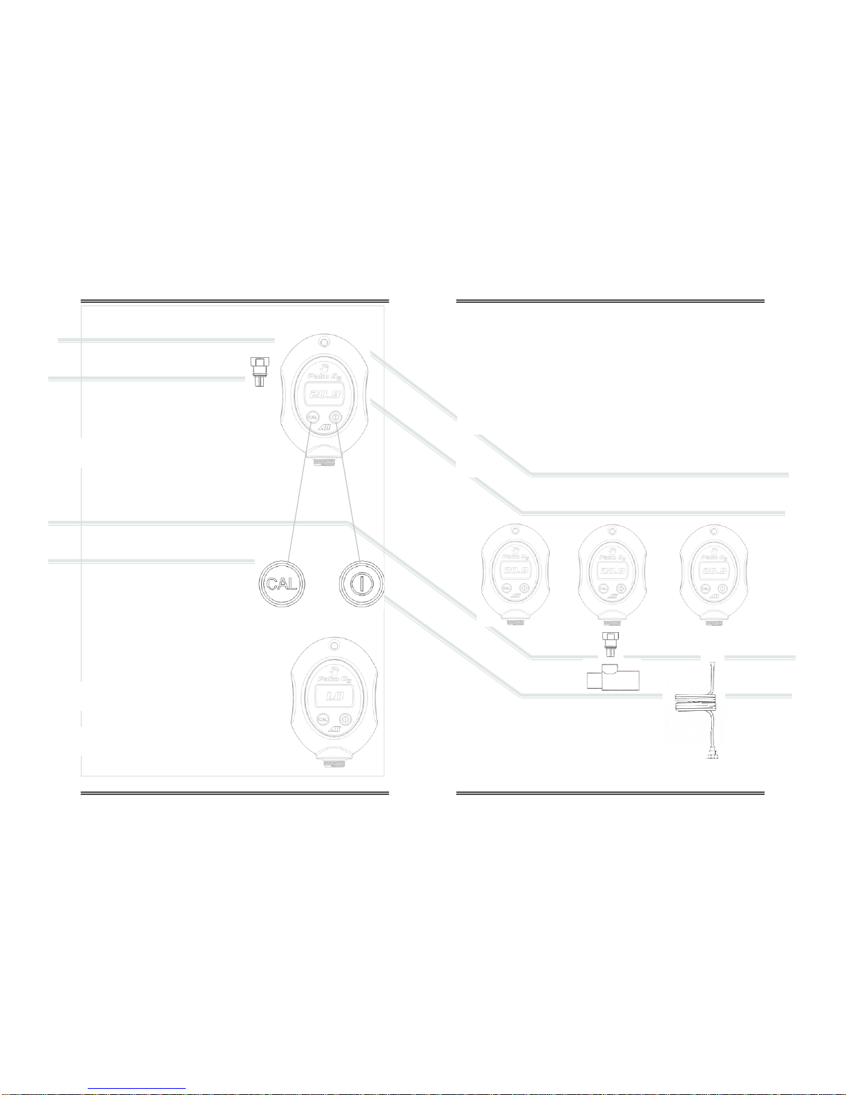
AII-2000 Palm O2 Oxygen Analyzer is battery powered by (2) AA alkaline bat-
teries and controlled by a state-of-the-art microprocessor. The batteries provide
enough power to operate the analyzer continuously for approximately 13,000
hours. Both devices utilize a membrane type keypad for users to communicate
commands to the microprocessor. The digital electronics provide features such
as system diagnostics and warning indicators that enhance both safety and
effectiveness. The design criteria, quality program and performance features
ensure reliable and accurate oxygen measurements.
13
5.2 Application Considerations
Effect of Anesthetic Agents
The AII-2000 Palm O2 Oxygen Analyzer utilizes an electrochemical galvanic
fuel cell type sensor, model AII-11-75-PO2, that has been characterized by its
gas permeable sensing membrane that allows the gas to be analyzed to diffuse
into the sensor where oxygen can be reacted. The displayed oxygen concentra-
tion of all sensors of this design decreases in the presence of anesthesia gases.
EN 12598:1999/ISO 7767:1997 (E) established standards for the maximum
error allowable over a given duration. The anesthetic agents listed (Halothane,
Enflurane, Isoflurane, Sevoflurane and Desflurance) were vaporized into a gas
stream of 30% oxygen / 70% nitrous oxide.
Gas Test Level Decrease in O2 Reading
Helium 50%, Balance O2 0%
Nitrous Oxide 80%, Balance O2 0%
Carbon Dioxide 10%, Balance O2 0%
Halothane 4% <-1.5%
Enflurane 5% <-1.5%
Isoflurane 5% <-1.5%
Sevoflurane 5% <-1.5%
Desflurane 15% <-1.5%
The errors listed were observed after a two (2) hour exposure period. The
table above summarizes the performance of the AII-2000 Palm O2 electronics
and AII-11-75-PO2 Oxygen Sensor. The above performances all meet or ex-
ceed the requirements established by EN 12598:1999/ISO 7767:1997 (E).
Do not operate any device in the presence of flammable anesthetic agents
such as Diethal Ether or Cyclpropane.
Note: The AII-11-75-PO2 Oxygen Sensor has been specifically designed and
tested to be compatible with nitrous oxide. For optimum results, mount oxygen
sensor with the sensing area facing down toward the floor and be flushed or
calibrated with 100% oxygen every eight (8) hours.
Effect of Temperature
All membrane clad electrochemical sensors are temperature dependent due to
the expansion and contraction of the Teflon sensing membrane. As result more
or less of the sample gas including oxygen to be reacted diffuses into the sen-
sor. The oxygen sensor’s electrical current signal output varies linearly with
oxygen concentration. The signal also varies with changes in ambient tempera-
ture. The temperature coefficient is typically 2.54% of the signal or reading per
degree C change in temperature.

14
The temperature dependent current signal output is compensated by using a
resistor-thermistor network. With a proper resistor-thermistor network, the
signal can be compensated to within +5% of the oxygen reading over the 5-
45°C temperature range. This is the worse case situation when going from one
extreme of the operating temperature range to the other. The error will be
eliminated when the thermistor in the temperature compensation network and
the electrolyte inside the sensor reach thermal equilibrium in approximately 45-
60 minutes.
Erroneous oxygen readings can result if the gases flowing over the
sensing area of the sensor are not at ambient temperature. This occurs
because the sensor is exposed to different temperatures. The sensing
area of the sensor is o-ring sealed in the heated breathing circuit and the tem-
perature compensation network at the rear of the sensor is exposed to ambient
temperature.
Effect of Pressure
Electrochemical sensors actually measure the partial pressure, not the percent-
age, of oxygen in the gas stream they are exposed to. These sensors are accu-
rate at any pressure provided the pressure is constant and the analyzer has
been calibrated at the same pressure as the sample gas measured.
For example, when connected to a gas stream where the pressure varies, the
oxygen sensor causes the analyzer to display fluctuating oxygen readings. The
fluctuations in the readings displayed are not related to a change in the oxygen
percentage but to the change in partial pressure resulting from the alternating
breathing pressure cycles of a ventilator which increases the total pressure.
Calibrate at the temperature and pressure (altitude) at which the ana-
lyzer will be operated.
Effect of Humidity
The analyzer is not affected by non-condensing relative humidity (RH). How-
ever, the use of a humidifier to introduce water vapor and increase the mois-
ture level of the gas mixture does affect the oxygen concentration and the
resultant reading displayed by the analyzer. The addition of water vapor in-
creases the total pressure thereby diluting or decreasing the oxygen concentra-
tion of the gas mixture resulting in a lower oxygen reading.
Calibrate at the temperature and pressure (altitude) at which the ana-
lyzer will be operated, humidified gases cannot be 100% oxygen.
15
Effect of Condensation
Excessive condensation collecting on the sensing area or the electrical connec-
tions at the rear of the sensors can adversely impact the performance of elec-
trochemical sensors. Condensation blocks the diffusion path of oxygen into the
sensor and can reduce the oxygen reading to 00.0 if the condensation covers
the entire sensing area. Condensation on the electrical connections at the rear
of the sensor can affect oxygen readings. Remedy either situation by shaking
out the condensation and allowing the sensor to air dry.
Erroneously characterized in many instances as a sensor failure, excessive
condensation is remedied by gently wiping away the condensation with a soft
cloth or simply allowing the sensor to air dry.
Effect of Electromagnetic Radiation
Tested over a 26 MHz to 1000 MHz electromagnetic field, the analyzer is sus-
ceptible at all frequencies tested except those between 930 and 990 MHz.
Never operate the analyzer near equipment capable of emitting high
levels of electromagnetic radiation. Do not continue to operate the
analyzer if the reading becomes unstable.
5.3 Calibration
Calibrating the analyzer during normal operation involves the same
precautions and procedures as those described in Sections 4.4 Start-up
Calibration with the same cautions to review Sections 3 Safety Warn-
ings and 5.2 Application Considerations.
5.4 Sampling
Assuming the START-UP TESTS are completed successfully the devices default
to the SAMPLING mode.
Never operate the analyzer if the reading is unstable or if a malfunc-
tion is suspected. If calibration is required as indicated herein, do not
proceed until the analyzer is calibration successfully.

16 17
5.4.1 Flowing Gas Streams (Breathing Circuits, Concentrators)
1. Place the sensing area of the sensor into the gas stream
to be analyzed upstream of any humidification equipment.
2. Assure that the flow rate of the gas stream does not ex-
ceed ten (10) liters per minute. Exceeding ten (10) liters
per minute generates backpressure.
3. Check the gas stream and particularly the mechanical
connection for leaks that dilute the gas stream with ambi-
ent air.
4. Assure there are no restrictions in the circuit downstream
of the sensor that could generate backpressure on the
sensor.
5. Use the flow diverter supplied with the device along with
the optional tee adapter and position the sensor vertically
for optimum results, as shown right. The flow diverter
avoids stagnation and facilitates the movement of gas to
and from the sensing area of the sensor thereby produc-
ing a more accurate measurement of the gas stream to be
measured.
6. Install the tee-adapter in the breathing circuit.
7. Screw the flow diverter to the sensor.
8. Ensure the o-ring is lightly lubricated for ease of entry and
a tight seal between the flow diverter and tee adapter.
9. Insert the assembled flow diverter/sensor into the tee
allowing 100% oxygen (dry, non-humidified) to flow past
the sensor at a rate of 5-8 liters per minute.
10. Once the sensing area of the sensor is exposed to the gas
stream allow approximately sixty (60) seconds for the
reading to stabilize and observe the reading displayed by
the LCD.
5.4.2 Static Atmospheres (Incubators, Hoods, Oxygen Tents)
Expose the sensing area of the sensor to the atmosphere al-
lowing approximately sixty (60) seconds for the reading to
stabilize and observe the reading displayed by the LCD.
If placing the entire sensor inside the controlled atmos-
phere review Section 5.2
6 Maintenance
Review Section 3 Safety Warnings and Section 7 Troubleshooting for
guidelines on servicing the devices.
6.1 Serviceability
Do not open the main compartment of the analyzer, as it contains no service-
able parts inside. Never attempt to repair the analyzer or sensor by yourself as
you may damage the analyzer which could void the warranty.
6.1.2 Cleaning / Reuse Instructions
Clean the device, oxygen sensor and accessories with a soft cloth dampened
with either water or mild isopropyl alcohol solution (70% isopropyl alcohol
solution in water), if necessary, before re-use. Allow the components to air-dry
after cleaning.
Note: The Home Care Kit is not intended for patient use, it is intended solely
for confirming the O2concentration in Oxygen Concentrators. Accordingly, no
cleaning instructions apply.
6.2 Battery Replacement
The AII-2000 Palm O2 Oxygen Analyzer is powered by two
1.5V AA alkaline batteries with an approximate life of 13,000
hours.
A low battery indicator circuit monitors the battery supply
voltage and sends a signal directly to the LCD when the bat-
tery voltage reaches a preset level that activates the battery
symbol in the LCD.
The batteries are located the top or front of the analyzer and secured by termi-
nals mounted directly on the PCB Assembly.

18
Procedure:
1. Open the enclosure: Remove the four (4) Phillips
screws from the rear of the enclosure, FIG 1.
2. Separate the enclosure and an place it on a flat
surface, FIG 2.
3. Remove the battery: Grasp the middle of a battery
and gently pull straight up.
4. Locate the positive (+) and negative (-) terminals
on the battery.
5. Assure the battery contacts are clean.
6. Align the battery’s positive (+) terminal with the
corresponding (+) battery symbol printed on the
PCB Assembly.
7. Install the battery: Align the battery over the termi-
nal clip mounted on the PCB Assembly and press
down until the battery snaps into place, FIG 2.
8. Repeat steps 3-7 with the remaining battery.
9. Reassemble the device as shown in section 6.4
10. Calibrate, see section 4.4, the device after replacing the batteries.
6.3 Oxygen Sensor Replacement - Standard Integral Sensor
The design of the electronics is intended for only the Analytical Industries Inc.
AII-11-75-PO2 or AII-11-75-PO2R Oxygen Sensors. Use of a different oxygen
sensor may result in an erroneous oxygen reading.
NEVER - Open the oxygen sensor or probe the sensing surface, refer
to Section 10 in the event the sensor should leak and someone comes
in contact with the electrolyte from inside the sensor.
Procedure - Standard Integral Sensor
1. See 6.2 step 1 above.
2. See 6.2 step 2 above.
3. Disconnect the oxygen sensor: Press
down on the latch arm, see arrow,
and pull back on the male connector
attached to the sensor from the fe-
male connector attached to the PCB
Assembly, FIG 3.
19
4. Remove the oxygen sensor, FIG 4:
(a) Lift up the rear of the sensor where
the connector wires are attached.
(b) Pull the front end of the sensor out
of the retaining collar, arrow right,
molded into the gasket that seals the
two sections of the enclosure.
5. Install the new oxygen sensor:
(a) Align the rear of the sensor as shown
in FIG 5, but do not install.
(b) Insert the sensor into the molded collar, arrow
FIG 6, and align the outer shoulder with the front edge of the collar.
(c) Locate the registration peg indicated by the arrow circled in FIG 5.
(d) Gently press the hole where the wires exit the sensor onto the
registration peg, FIG 5.
6. Connect the sensor, reverse section step 3.
7. Reassemble the device as shown in section 6.4.
8. Calibrate, see section 4.4, the device after replacing
the sensor.
6.4 Reassembly
To ensure proper operation after replacing the sensor or
batteries check the following points:
1. The batteries are secured in the terminal clip.
2. The sealing gasket is registered onto the 4 pegs molded into the
bottom section of the enclosure.
3. The sensor is registered as shown in FIG 5 and FIG 7 and the connecting
wires are not bent or bound when closing up the enclosure and tightening
the Phillips screws, FIG 6.
FIG 7
FIG 1
FIG 2
FIG 3
FIG 5
FIG 4
FIG 6

6.5 Oxygen Sensor Replacement - Optional Remote Sensor
The design of the electronics is intended for only the Analytical Industries Inc.
AII-11-75-PO2 or AII-11-75-PO2R Oxygen Sensors. Use of a different oxygen
sensor may result in an erroneous oxygen reading.
NEVER - Open the oxygen sensor or probe the
sensing surface, refer to Section 10 in the event
the sensor should leak and someone comes in
contact with the electrolyte from inside the sensor.
With this configuration the integral oxygen sensor is re-
placed by a connector module (P/N A-3654). The external
oxygen sensor (P/N AII-11-75-PO2R) is connected to the
module by a cable (P/N CABL-1009) with phone plug and
locking nut attached at both ends. The cable is coiled and
extends to 6 ft.
Procedure - Optional Remote Sensor
1. Unscrew the locking nut from the connector located
at the rear of the oxygen sensor.
2. Remove the new replacement sensor from its shipping
packaging.
3. Insert the phone plug into the connector at the rear
of the oxygen sensor and finger tighten the locking nut.
4. Allow the new replacement oxygen sensor to stabilize
for approximately 30 minutes in its new environment.
5. Calibrate, see section 4.4, after replacing the remote
oxygen sensor.
20
7 Troubleshooting
If the recommended corrective action does not resolve the problem return the
device to the factory for service.
21
Symptom Corrective Action
Device appears to be physi-
cally damaged Turn device ON – if it successful passes
calibration – proceed
No display when analyzer is
turned ON Replace batteries
Check battery polarity
Check and/or clean battery contacts
‘LO’ displayed when analyzer is
turned ON or in use. Replace battery and calibrate device
‘ERR’ displayed when analyzer
fails calibration Replace oxygen sensor
No response to keypad Replace battery
Cannot turn device OFF Calibration routine in process – wait until
completed
Reading displayed by LCD
does not change when oxygen
level changes
Replace sensor
Reading does not stabilize or
fluctuates erratically Relocate analyzer away source of RF or
electromagnetic radiation emissions.
Wait 5 minutes and repeat calibration
Replace sensor, repeat calibration
After calibration in 100% dry
oxygen, analyzer reading drifts
more than 2% over 8 hours
Check primary oxygen delivery device
Replace sensor that is nearing the end of
its useful life

8 Specifications
22
8.1 Spare Parts & Optional Accessories
23
Accuracy: < 2% of FS range under constant conditions
Analysis: 0-100% oxygen
Alarms: Analyzer none
Calibration: Certified dry 100% oxygen or air after 8 hrs of use
Compensation: Temperature
Connections: 1x16mm thread or o-ring diverter
Controls: Soft touch keypad for ON/OFF and CAL
Dimensions: 2.72” x 4.1” x 1.35”; weight 7 oz. (196 grams)
Display: 3 digit LCD 1.1” x .625”; resolution 0.1% O2
Flow Sensitivity: None between 0.2 to 10 liters per minute
Humidity: Non-condensing 0-95% RH
Linearity: + 1% under constant conditions
Pressure: Inlet – ambient or regulated; vent - atmospheric
Power: (2) 1.5V AA alkaline batteries; 13,000 hrs of use
Response Time: 90% of final FS reading in 10 seconds
Sensitivity: < 0.5% of FS range
Sensor: AII-11-75-PO2; optional remote sensor AII-11-75-PO2R
Sensor Life: 32 months in air at 25ºC and 1 atmosphere
Storage Temp.: -20º to 60ºC (-4ºF to 140ºF) on intermittent basis
Temp. Range: 5º to 45ºC (41ºF to 113ºF)
Warm-up Time: None
Warranty: 12 months analyzer; 12 months sensor (any application)
Spare Parts:
AII-11-75-PO2 Oxygen Sensor
BATT-1008 Battery (2x) 1.5V AA Alkaline
P-1087 Instructions for Use
A-1162 PCB Assy Main
FITN-1112-1 Flow Diverter, O-ring Seal
Optional Accessories:
HRWR-1157 Screwdriver
HRWR-1158 Lanyard

24
9 Warranty
Coverage
Under normal operating conditions, the analyzer and sensors are warranted to
be free of defects in materials and workmanship for the period specified in the
current published specifications. To make a warranty claim, you must return the
item properly packaged and postage prepaid to:
Analytical Industries Inc.
2855 Metropolitan Place
Pomona, Ca 91767 USA
T: 909-392-6900, F: 909-392-3665
E: sales-medical@aii1.com, W: www.aii1.com
Analytical Industries in their sole discretion shall determine the nature of the
defect. If the item is determined to be eligible for warranty we will repair it or,
at our option, replace it at no charge to you. If we choose to repair your item,
we may use new or reconditioned replacement parts of the same or upgraded
design. This is the only warranty we will give and it sets forth all our responsi-
bilities, there are no other express or implied warranties.
The warranty begins with the date of shipment from Analytical Industries and is
limited to the first customer who submits a claim for a given serial number
which must be in place and readable to be eligible for warranty and will not
extend to more than one customer or beyond the warranty period under any
conditions.
Exclusions
This warranty does not cover normal wear and tear; corrosion; damage while in
transit; damage resulting from misuse or abuse; lack of proper maintenance;
unauthorized repair or modification of the analyzer; fire; flood; explosion or
other failure to follow the Owner’s Manual.
Limitations
Analytical Industries shall not liable for losses or damages of any kind; loss of
use of the analyzer; incidental or consequential losses or damages; damages
resulting from alterations, misuse, abuse, lack of proper maintenance; unau-
thorized repair or modification of the analyzer.
Service
Contact us between 8:00am and 5:00pm PST Monday thru Thursday or before
12:00pm on Friday. Trained technicians will assist you in diagnosing the prob-
lem and determining the appropriate course of action.
25
10 MaterialSafetyDataSheet (MSDS)
10.1 Disposal
Oxygen sensors and batteries should be disposed of in accordance with local
regulations for batteries.
WEEE regulations prohibit electronic products including the He-
lium and environmental sensors from being placed in household
trash bins.
Electronic products should be disposed of in accordance with local
regulations.
Product name Electrochemical Galvanic Fuel Cell Oxygen Sensor
Exposure Sealed device with protective coverings, normally no hazard
Ingredients Carcinogens - none; Potassium Hydroxide (KOH), Lead (Pb)
Properties Completely soluble in H2O; evaporation similar to H2O
Flash Points Not applicable, non-flammable
Reactivity Stable; avoid strong acids, emits fumes when heated
Health Hazard KOH entry via ingestion - harmful or fatal if swallowed;
eye - corrosive, possible loss of vision;
skin contact - corrosive, possible chemical burn.
Liquid inhalation is unlikely.
Lead - known to cause birth defects, contact unlikely
Symptoms Eye contact - burning sensation; skin contact - slick feeling
Protection Ventilation - none; eye - safety glasses; hands - gloves
Precautions Do not remove Teflon and PCB coverings; do not probe with
sharp objects; avoid contact with eyes, skin and clothing.
Action KOH
Leak Use rubber gloves, safety glasses and H2O and flush all
surfaces repeatedly with liberal amounts of H2O
Table of contents
Other Analytical Industries Analytical Instrument manuals