Analyticon Urilyzer 100 Pro User manual

agile - affordable - accurate
Urilyzer®100 (Pro)
User Manual
Analyticon
Biotechnologies AG
Am Muehlenberg 10
35104 Lichtenfels - Germany
www.analyticon-diagnostics.com

3
Analyticon Biotechnologies AG
Am Muehlenberg 10
35104 Lichtenfels - Germany
www.analyticon-diagnostics.com
The information in this manual was correct at the time of printing.
However, Analyticon Biotechnologies AG continues to improve its products and
reserves the right to change specifications, equipment, and maintenance proce-
dures at any time without notice.
Companies, names and data used in examples are fictitious unless otherwise
noted. No part of this document may be reproduced or transmitted in any form or
by any means, electronic, mechanical or otherwise, for any purpose, without the
express written permission of Analyticon. Analyticon may have patents or pend-
ing patent applications, trademarks, copyrights or other intellectual or industrial
property rights covering this document or subject matter in this document. The
furnishing of this document does not give a license to these property rights ex-
cept as expressly provided in any written license agreement from Analyticon.
If this instrument is used in a manner differently than specified in this manual, the
protection provided by the equipment may be impaired.
V1.03 (GB) (2012-11)

3
Table of Content
Table of Contents
1. Introduction 5
1.1 How to use this manual 5
2. Quickstart 8
3. System description 10
3.1 Measuring principle 10
3.2 Components and Functions 11
3.3 Instrument and Labeling Symbols 12
4. Unpacking & Set Up 14
4.1 Unpacking 14
4.2 Setting up 14
4.3 Analyzer software updates 18
5. Use of the instrument 20
5.1 Screens 20
5.2 Interacting with the touch screen 20
5.3 Data input: Barcode reader, keyboard 23
5.4 Flow-chart of the menu structure 25
6. Start-Up Wizard 27
7. Testing 28
7.1 Quick Test 28
7.2 Test features and customization 31
7.3 Full Test 34
7.4 Latest result 36
7.5 Worklist management 36
8. Recall Results 39
8.1 List view 39
8.2 Result view 40
8.3 Filtering: How to find specific results 40
8.4 Modifying the active selection of results 41
8.5 Action with selected items 42
9. Quality Control Testing 43
9.1 QC Options 44
9.2 QC Testing 46
9.3 Recall QC Results 47

4
Table of Content
10. Options menu 48
10.1 Strip LOT 48
10.2 View Settings 48
10.3 User Options 48
11. Instrument Settings 50
11.1 Language 51
11.2 Date, time 51
11.3 Printout 51
11.4 Output (Connectivity: Transfer/Export) 52
11.5 Measurement 54
11.6 Strip options 54
11.7 Database management 55
11.8 QC options (Pro only) 55
11.9 Power management 56
11.10 Log export 56
11.11 Editing color and clarity list (Pro only) 56
11.12 Ethernet interface configuration (Pro only) 57
11.13 Update 57
11.14 Operators (Pro only) 58
12. Cleaning & Maintenance 64
12.1 Cleaning the analyzer 64
12.2 Cleaning the test strip tray 64
13. Troubleshooting 66
13.1 List of Errors and Information Messages 67
13.2 Problem Checklist 78
14. Appendices 79
14.1 Appendix A: Results table 79
14.2 Appendix B: Specifications 81
14.3 Appendix C: Analyzer Default settings 82
14.4 Appendix D: Safety information 83
14.5 Urilyzer 100 Intended Use and Indications for Use 85

5
Introduction
1 Introduction
Due to software changes, some screens on the instrument may appear slightly
different from those in this manual.
What does the analyzer do?
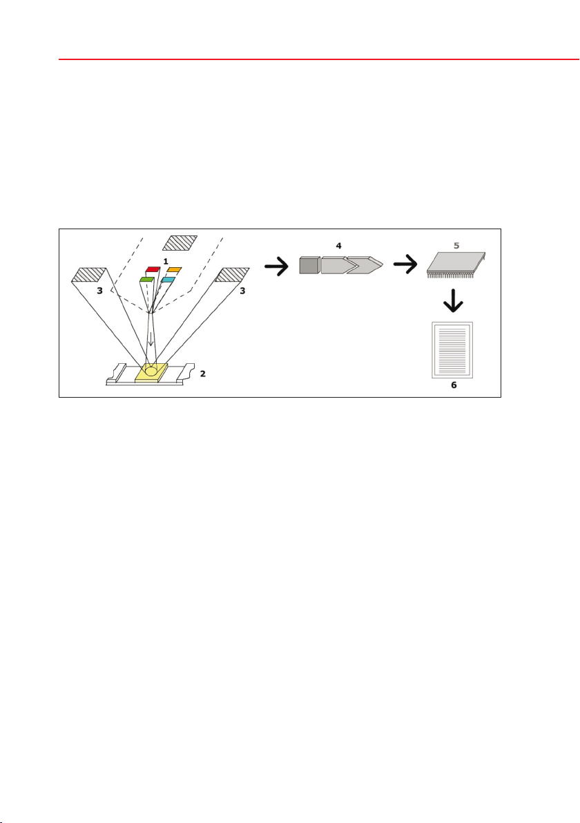
The Urilyzer 100 analyzer is a lightweight instrument for reading CombiSceen
Plus urinalysis strips (CombiScreen 11SYS Plus, CombiScreen 7SYS Plus and
CombiScreen 5SYS Plus). It is a reflectance photometer that analyzes the inten-
sity and color of light reflected from the reagent areas of the strip. It is designed
for In Vitro Diagnostic (IVD) use by qualified physicians and laboratory staff; how-
ever no special training is required to operate the instrument.
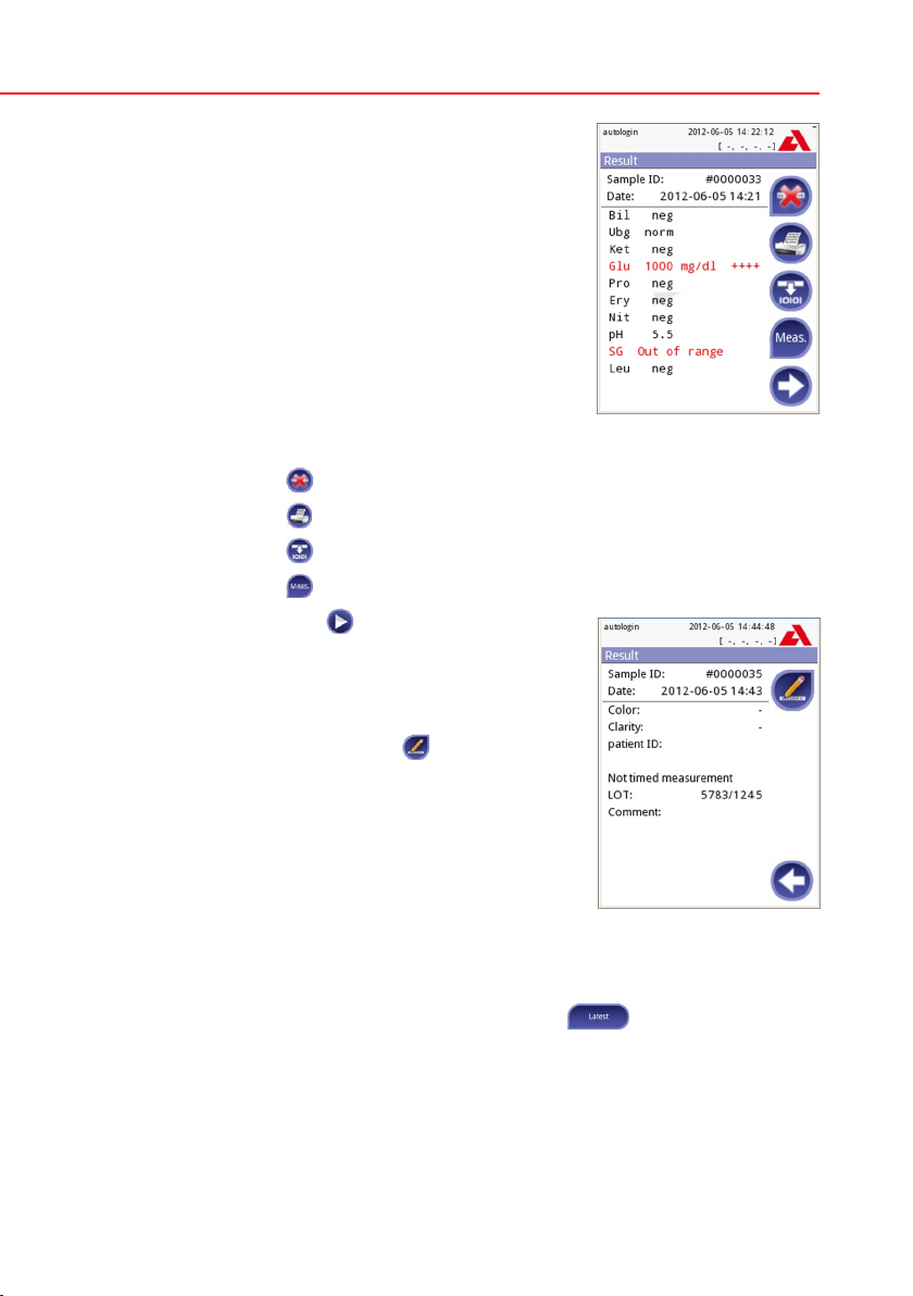
The analyzer can be set up to be as simple or sophisticated as you prefer. You
may simply insert a dipped urinalysis strip into the analyzer and the result will be
reported. By modifying the user options the measurements can be automatically
started, printed and transferred.
Alternatively, you have the option to enter the Sample ID, Patient ID, and color,
clarity of the specimen manually. This added information will be reported along
with the test results. The system also allows full customization to determine
which fields appear on the printouts. You can also enable the user manage-
ment features, thus the Operator ID is also recorded with the test results. The
advanced security functions may also prevent unauthorized use through config-
urable settings. Remember, these features can be set independently.
The touch screen displays instructions and prompts you through the operation
of the analyzer. In addition, you enter information through the touch screen. The
optional barcode reader and external keyboard are also available for accurate
data entry to reduce transcription errors.
Do I have to calibrate?
You do not have to do anything to calibrate. The instrument performs a system
test each time it is turned on. Then, each time a test is run, the instrument auto-
matically checks and corrects its performance through the independent internal
sensor.
1.1 How to use this manual
The Operator’s Manual contains the directions you need to unpack the analyzer,
safely use it for your daily urinalysis and keep it in good working condition.
Symbols
Symbols are used to help quickly locate and interpret information in this manual.
This section explains the formatting conventions used in this manual.
The following symbols are used throughout this document:

6
Introduction
7
Symbol/Sign Explanation
CAUTION: Indicates a potentially hazardous situation that if not
avoided could result in personal injury or damage to the instru-
ment. This symbol is also used to highlight situations that can
compromise results. Cautions appear in bold type.
BIOHAZARD: Indicates a potentially dangerous situation involv-
ing the presence of biohazardous material. All safety precau-
tions must be taken to prevent personal injury or damage to the
equipment.
NOTE: Contains important information or useful tips on using
the analyzer. Notes appear in italicized type.
The sign labels a cross-reference inline the text. In the manual, you will notice
some text is in bold/italic or bold. The bold/italic text identifies screen names,
while simple bold text identifies a button (touch sensitive area) on the screen.
Safety precautions
Before operating the Urilyzer 100 analyzer, it is essential that the warnings, cau-
tions, and safety requirements contained in this manual are read and understood
by the user.
Detailed safety information can be found in 14.4 Appendix D: Safety
information section.
User qualification: Only appropriately trained operators are qualified to
operate the analyzer.
Correct use: Any disregard of the instructions in the Operator’s Manual
may result in a safety risk. Use the Urilyzer 100 analyzer to analyze urine
samples only. It is not intended for any other application.
Environmental conditions: The Urilyzer 100 analyzer is approved for in-
door use only.
Strip waste is potentially biologically hazardous. Always wear personal
protective equipment when handling and disposing of samples of hu-
man origin. Use universal precautions. Consult your facility’s infection
control policy. See 14.4.1 Protecting yourself from biohazards sec-
tion for more information.

6
7
Introduction
Abbreviations
The following abbreviations are used:
Abbreviation Definition
AC Alternating Current
arb arbitrary
ASTM American Society for Testing Material
conv conventional
csv comma separated values
DC Direct Current
EN European Standard
ID Identification number
LED Light Emitting Diode
neg negative
norm normal
pos positive
SI Standard International

8
Quickstart
9
2. Quickstart
Unpack the instrument and place it on an even, hard surface (for detailed instal-
lation instructions see 4. Unpacking & Set Up). Load the strip tray and the
printer paper.
Connect the power supply and turn the reader on with the On/Off-switch (See
4.2.5: Powering up).
After the boot-up procedure and self-test the Mea-
surement screen will appear on the display.
Strip waste is potentially biologically hazard-
ous. Always wear personal protective equip-
ment when handling and disposing of sam-
ples of human origin. Use universal precau-
tions. Consult your facility’s infection control
policy. See 14.4.1 Protecting yourself from
biohazards section for more information.
• Dipateststick(CombiScreen11SYSPlus)intotheurinesampleforapprox.
one second.
• Blot by touching the edge of the strip to a paper towel to remove excess
urine.
• Placethestriponthestripholder
• Slideor pushthe stripto theend ofthe channel.Do nottouch thereagent
pads on the test strip.
The instrument will automatically detect an applied strip. The measurement cycle
will be started. A progress bar on the display shows the remaining incubation
time.
If „Autostart“ (see 7.2.1 Features: Autostart-, print-, transfer- and fast
mode) is deactivated, the measurement must be started by pressing the Start
button.
Measurement

8
9
Quickstart
After approx. 60 seconds the pad results will be dis-
played on the screen.
If Autostart is ON: The result screen will be dis-
played until you remove the test strip from the tray.
Once the strip is removed, the display automatically
returns to the Measurement screen.
If Autostart is OFF: The result screen will be dis-
played for approximately 5 seconds –while display-
ing a circle animation – then the display will return
to the Measurement screen (if no error occurred
during the readout). If you touch the display while
the circle animation is running, the system will not
automatically return back.
On the Result screen:
• Bypressingthe Delete button the result can be deleted
• Bypressingthe Printer symbol the result can be printed
• Bypressingthe Transfer button the result can be transferred
• Bypressingthe Meas. button the system goes back to the measurement
• Bypressingtheright arrow the additional fields
of the result are showed
– Color, clarity, Patient ID, Strip LOT and com-
ment
– On the second result screen the result can
be edited by pressing the Edit button (if it
wasn’t printed or sent already)
At the Measurement screen another analysis may be started by applying the
next test strip.
The latest result can be reviewed by selecting the Latest button on the
Measurement screen.
Result (1)
Result (2)

10
System description
11
3. System description
3.1 Measuring principle
The test strip is moved below a fixed measurement unit on a slide called test strip
tray with an embedded reference pad. The analyzer reads the reference pad, fol-
lowed by each of the test pads on the strip.
The optical unit contains four LEDs that emit light at various wavelengths. Read-
ing is done electro-optically, as follows:
The LEDs (1) subsequently emit light of a defined wavelength onto the surface of
the test pad (2) from directly above the test zone. The light hitting the test zone is
reflected more or less intensely depending on the degree of color change of the
test pad (directly related to the concentration of the particular constituent in the
urine), and is picked up by the detectors, photodiodes (3) positioned at optimum
angles. The phototransistors send analogue electrical signal to an A/D converter
(4), which changes it to digital form. The microprocessor (5) then converts this
digital reading to a relative reflectance value by referring it to a calibration stand-
ard.
Finally, the system compares the reflectance value with the defined range limits
(reflectance values that are programmed into the analyzer for each parameter)
and outputs a semi-quantitative result (6).
Each test pad is read photometrically after a lead (incubation) time of about 55–
65 seconds.
Principle of measurement

10
11
System description
Component Function
1. Printer cover Flips up for insertion of printer paper
2. Printer cover button Push to open the printer cover
3. Display LCD touch screen for interfacing with the user
4. Test strip tray Holds the strip
5. Power inlet socket Socket used to connect the analyzer to the mains
adapter
6. PS2 socket For connecting a barcode reader or a keyboard
7. Serial interface For connecting a personal or host computer
8. USB B socket Socket used for serial-USB
9. Ethernet socket (Pro) Socket used to connect the analyzer to an Ethernet
network
10. USB A sockets Multifunctional socket used to connect USB devices
11. On/Off switch Powers the unit on. May be used to power the unit
off.
The standard power off procedure should be started
from the user interface.
Only connect the intended devices to the corresponding interface. If
you connect another device to the corresponding interface, the device
or the analyzer may be damaged e. g. because of wrong voltage. Be
sure to check all cables you are using to make sure they are opera-
tional. Verify the proper connection.
Front view Rear view
1
2
3
4
5 6 7 8 9 10 11
3.2 Components and Functions

12
System description
13
3.3 Instrument and Labeling Symbols
This section describes the symbols that appear on the exterior of the Urilyzer 100
analyzer, the power supply provided with the instrument, the packaging in which
the instrument was delivered and the supplies of reagent strips which you will
use with the instrument.
Double insulated product or
transformer may also identi-
fy class 2 equipment (power
supply only)
Indoor use only
Identifies that the instru-
ment is listed by Underwrit-
ers Laboratories as meeting
U.S. and Canadian require-
ments for safety
The CE mark identifies that
the product complies with
the applicable directives of
the European Union
This product has been tested
to the requirements of CAN/
CSA-C22.2 No. 61010-1,
second edition, including
Amendment 1, or a later ver-
sion of the same standard
incorporating the same level
of testing requirements.
This system contains cer-
tain toxic or hazardous sub-
stances or elements. The
environmental protection
use period for this system
is 10 years. The system can
be used safely during its en-
vironmental protection use
period. The system should
be recycled immediately af-
ter its environmental protec-
tion use period has expired.
Indicates that this equip-
ment is classified as Waste
Electrical and Electronic
Equipment under the Eu-
ropean WEEE Directive. It
must be recycled or dis-
posed of in accordance
with applicable local re-
quirements.
In vitro diagnostic medical
device
Caution, consult accompa-
nying documents
Manufacturer Catalog number
Consult instructions for use Serial number

12
13
System description
Indicates a power on/off
button
USB port symbol
Ethernet port symbol DC Adaptor Polarity Centre
Positive
Do not use if package is
damaged
Keep this way up
Handle with care
4
Stack no more than 4
-25°C
(-13°F)
60°C
(140°F)
Temperature limitation
10%
85%
%
Humidity limitation
70 kPa
106 kPa
Atmospheric pressure limi-
tation
Batch code Use by date
The number of items that
the contents of the pack is
sufficient for
Do not reuse
Protect from sunlight and
heat
Keep dry

14
Unpacking & Set Up
15
4. Unpacking & Set Up
4.1 Unpacking
Read the Urilyzer 100 Operator’s Manual carefully before installation,
so as to ensure proper operation of the analyzer from the outset.
Follow the specified installation instructions carefully. Otherwise, inac-
curate results or damage to the analyzer may occur.
Check the carton and instrument for visible signs of damage; if seen, contact the
carrier immediately.
Carefully remove the contents of the shipping carton, remove each of the wrap-
pings and check for the following items:
List of delivered parts:
• Urilyzer100analyzer
• Powersupply
(AC Adapter 100V–240V, 50/60 Hz)
• Powersupplycord
If the power cord is not the style you
need, contact your service repre-
sentative
• Operator‘sManualCD
• QuickReferenceGuide
• Teststriptray(2x)
Do not touch the reference pad
• Rollofprinterpaper
• Checkstrip(1x)
Do not touch the check area, hold it by the handle
4.2 Setting up
Place the instrument on a solid, level surface where the temperature and humid-
ity are fairly constant.
Make sure the instrument is allowed to acclimatize to room temperature prior
to use.
Make sure that you
• Donotplacetheinstrumentincloseproximitytosourcesofstrongelec-
tromagnetic radiation or vibration sources
•
Do not place the instrument near heater devices, ovens or air conditioners
Contents

14
15
Unpacking & Set Up
• Do not expose the instrument to strong light sources (e.g. direct sun-
light)
4.2.1 Plugging analyzer in
Only use the power supply adapter included with the unit. Connect the
analyzer to grounded power outlets only.
1. Plug the cable of the power supply
into the power inlet socket located
on the rear of the Urilyzer 100 ana-
lyzer.
2. Plug the appropriate end of the pow-
er cord into the power supply.
3. Plug the other end of the power cord
into a readily accessible AC electri-
cal wall outlet.
4.2.2 Inserting test strip tray
Do not touch the reference pad.
Insert the test strip tray into the analyzer by holding it by the end with the open-
ing (opposite the reference pad) and with the channel facing up. Push the test
strip tray into the analyzer, pushing it in until the reference pad disappears into
the housing.
Analyzer plugged in
Loading test strip tray

16
Unpacking & Set Up
17
4.2.3 Loading the paper roll
Open the printer cover by pushing the printer cover button. The cover can then
be lifted back.
The printer head may be hot, do not touch it.
Place the paper roll in the compartment and pull out the first few centimeters of
paper just beyond the edge of the compartment. The thermosensitive side of the
paper (the outer surface of the paper roll) should be facing downwards. Close the
cover again by pressing until it locks audibly into position.
To remove the printed test report, tear off the paper by pulling it towards the
front across the edge.
The analyzer is set up to print the results automatically (to turn off the auto-
matic print function see 7.2.1 Features: Autostart-, print-, transfer- and fast
mode).
Opening the printer cover Loading the printer paper
Analyzer loaded with paper

16
17
Unpacking & Set Up
4.2.4 Interfacing to a computer
The instrument can send results to a computer via the serial port located on the
back of the analyzer. This requires a D-sub, 9-pin serial cable (male on instru-
ment side, female on PC side).
Connections:
Urilyzer 100 Host (PC pinout 9-pin)
1 1
2 ——————TxD—————— 2
3
——————
RxD
——————
3
4 4
5
——————
GND
——————
5
6 6
7 7
8 8
9 9
Connected PC must satisfy the electrical safety requirements laid down in EN
60950.
4.2.5 Powering up
Press the On/Off button located at the rear of the instrument. The system starts
with an audible beep.
Picture 9: Powering up

18
Unpacking & Set Up
19
4.2.6 Powering down
Do not remove the power cable while the instrument is operating, otherwise the
data may be corrupted or the system may be compromised.
Before turning the analyzer off, always ensure that there is no strip on the test
strip tray and that the tray is clean.
The analyzer is switched off by pressing the button on the Main or on the
Login (Pro) screen. The test strip tray will retract into the analyzer.
We recommend that the analyzer be switched off at the end of each working day
and that the mains adapter be unplugged from the AC wall socket.
If necessary, the analyzer can also be switched off by holding down the On/Off
button for at least 5 seconds. Please note that this feature should be used in
case of system freeze or LCD failure. In this case the test strip tray will not be
retracted.
4.3 Analyzer software updates
From time to time Analyticon will add new features and make improvements to
the Urilyzer 100 analyzer software.
Updating the software is a simple procedure, but for the upgrade to work prop-
erly, it is important to follow the instructions below precisely.
A previously prepared USB flash drive is required for the upgrade.
Either you will receive an already prepared USB flash drive from your local
distributor or you will have to upload the update files manually to a USB flash
drive if you received the software update in electronically distributed package.
Instructions for preparation of the USB flash drive can be found in the next
chapter.
Power on the instrument and wait until the system is ready to use.
Powering down

18
19
Unpacking & Set Up
Plug the USB flash drive into one of the USB A connectors on the back of the
device. Wait until the disk icon appears in the status line. The icon shows that
the USB flash drive was recognized by the system.
Go to Settings (2)»Update screen. The analyzer recognizes that a software
update package is available and verifies the integrity of the package. If the pack-
age is verified, the Update button will be available.
If no update source was found by the system, the button name is changed to
Refresh. Push the Refresh button to force the system to check again all up-
date peripherals.
To start the process, press the Update button. The update will be performed
automatically.
After the update is finished successfully, press the Restart button and remove
the USB flash drive.
Please note that the update process will not overwrite or delete the existing
database or your settings.
4.3.1 Preparation of the USB flash drive
If you received the software update in electronically distributed format, please
follow these instructions for preparation of the USB flash drive.
To copy the update package on the USB drive you will need a PC and some
basic knowledge of the operating system.
1) Create an ’update’ directory in the root of the USB drive.
2) Unzip and copy the content of the whole package into the ’update’ directory.
The file names will be similar to these: udr2base_x.x.x.tar.gz, udr2base_x.x.x.tar.
gz.chk, iUD2vX, iUD2vX.chk (x, X are replaced with numbers). In case of Uri-
lyzer 100 Pro ‚base‘ is replaced with ‚pro‘.
4.3.2 Available sources for software updates
The software update is possible from various sources:
• USBashdrive,
• microSDcard,
• codechip.
If you receive an updated description with the software update, please
follow those instructions.
The sockets for external microSD card and code chip are located under the
printer cover and are on the right-hand side of the printer when you face the front
of the instrument. The code chip socket is above the microSD card socket.
Special instructions for updating the software on your instrument from mi-
croSD card or code chip will be supplied with them.

20
Use of the intrument
21
5. Use of the instrument
All inputs are done via the touch screen (if no external keyboard or barcode
reader is attached).
5.1 Screens
The touch screen guides you through the operation of the Urilyzer 100 analyzer.
The screen displays messages, instructions and options to which you respond
by touching the appropriate area on the screen.
The screen layout can be divided into three main areas:
(1) Header: Displays important system information,
like date&time, user ID (Pro), queue and status line
messages.
The color background of the status bar changes
with the state of the system. Yellow means warn-
ing, red means error.
The active errors and warnings can be listed by
pressing the status bar area.
(2) Content navigation: Indicates the main and sub-
sections in which you are working. It gives you a way
to keep track of your location within the program.
The »sign serves as hierarchy separator.
(3) Content area: Main operation area
The first main screen you see is the Measure screen.
In the work area you can facilitate a measurement, review the last result, handle
the worklist, cycle through the worklist items and go to the QC, Main and Data
screens.
In some cases, the screen will also display instructions, messages or error mes-
sages.
5.2 Interacting with the touch screen
How to touch the display
The screen needs to be touched gently, but firmly in the touch-sensitive area to
activate a response. The touch-screen can be operated while wearing gloves.
Never use a hard or sharp object to operate the touch screen as they
can damage the screen.
A separate foil layer is attached to screen in order to prevent liquid leakage into
the system.
By default the sound is switched on. A successful touch event is also con-
firmed with a short beep signal.
Layout
Table of contents
Other Analyticon Measuring Instrument manuals