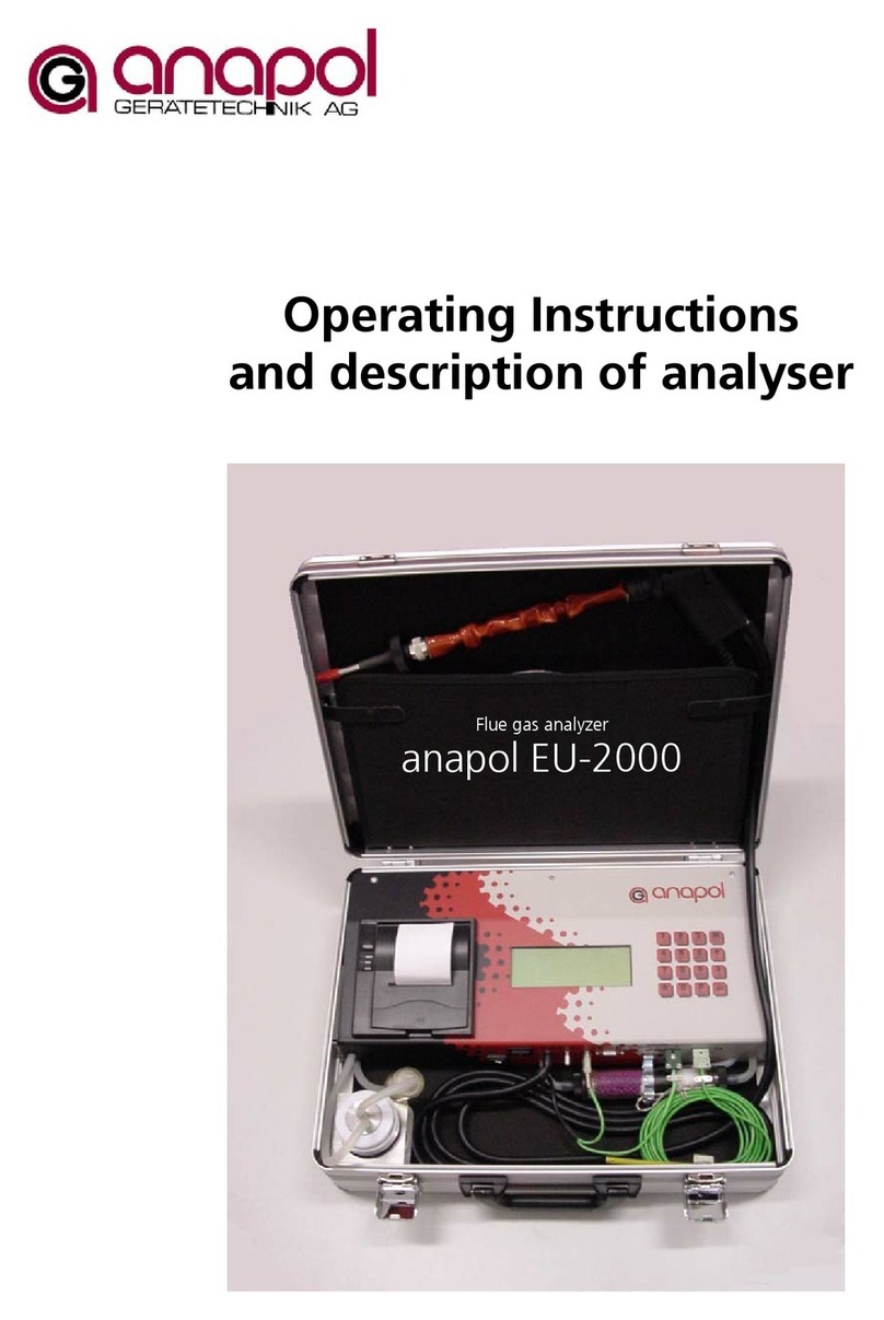
Anapol EU-50 Technical Document

Operating Instructions
and Equipment Description
Exhaust gas analyzer
anapol EU-50

Page 2
Dear customer,
By buying this device, you have demonstrated your confidence in us and we thank you sincerely for this.
In order that the device always operates impeccably, we would ask you to kindly read through these
operating instructions carefully and to follow the advice and tips included. By handling the device correctly
and taking care of it, you will be contributing to the maintenance of its value.
The device has already undergone stringent inspection procedures during its development and
manufacture. It complies with the highest technical requirements.
Our customer service department is at your disposal at all times and will be delighted to offer you optimal
and efficient help if necessary.
Your anapol team,
Anapol Instrument Engineering Inc
Gewerbepark Moosweg 1
CH-2555 Brügg, Switzerland
Tel: +41 (0)32 374 25 45
Fax: +41 (0)32 374 25 47
e-mail: [email protected]
www.anapol.ch

Software Version 3. NN/Brügg BE, June 2005
The description of the software for the device is based on Version 3.NN (M.NN) of June 2005.
M = Figure that describes the version of all the characteristics of the devices that are specified by metas
(metrology and accreditation Switzerland).
NN = Figure that describes the version of all other characteristics of the device, e.g. data storage, special
customer requests, Bugfix, new hardware components, etc.
EU-50 exhaust gas analysis computer
On the basis of article 17 of the Federal Law on Metrology of 19 June 1977 and according to the Directive
of 27 August 1987 on exhaust gas test equipment for combustion plants that are operated using "extra
light" heating oil and natural gas, this device was approved by metas with their letter dated 1 July 2005 by
means of indenture number 28 (in approval symbol). The scope of this approval is described in Art. 1 of the
above-mentioned Directive. The device is intended above all for official combustion plant inspections.
28
F
UPDATE SIGNATURE DATE
Updated MaV 23.11.06
EMC conformity MaV 23.11.06
Page 3

Page 4
CONTENTS
1Introduction ...................................................................................................................................5
1.1 Utilization/intended use .............................................................................................................................. 5
1.2 Preventive measures.................................................................................................................................... 5
1.3 Function...................................................................................................................................................... 5
1.4 Device description....................................................................................................................................... 6
2Operation ......................................................................................................................................7
2.1 Commissioning ........................................................................................................................................... 7
2.1.1 Procedure:................................................................................................................................................................................... 7
2.1.2 Switch device on. ..................................................................................................................................................................... 7
2.2 Calibration.................................................................................................................................................. 8
2.3 Measurement ........................................................................................................................................... 10
2.4 Printing..................................................................................................................................................... 11
2.4.1 Printing measurements......................................................................................................................................................... 11
2.4.2 Save measurements............................................................................................................................................................... 13
2.4.3 Printer options ......................................................................................................................................................................... 14
3Menu...........................................................................................................................................15
3.1 Draft (fine draft measurement).................................................................................................................. 15
3.2 Change paper........................................................................................................................................... 16
3.3 Diagnosis .................................................................................................................................................. 17
3.4 Language.................................................................................................................................................. 17
3.5 Communication ........................................................................................................................................ 18
3.5.1 Chip card................................................................................................................................................................................... 18
3.5.2 Communication ...................................................................................................................................................................... 19
3.5.3 Saving measurements ........................................................................................................................................................... 19
3.6 Free fuels .................................................................................................................................................. 21
3.7 Address..................................................................................................................................................... 22
3.8 Settings..................................................................................................................................................... 23
3.9 Date + time............................................................................................................................................... 24
3.10 Information............................................................................................................................................... 24
4Text entry.....................................................................................................................................26
5Special functions ..........................................................................................................................27
6Customer data .............................................................................................................................28
7BUWAL measurement ..................................................................................................................29
8Rechargeable batteries .................................................................................................................32
9Error messages.............................................................................................................................33
9.1 Error messages before calibration ............................................................................................................. 33
9.2 Error message during calibration............................................................................................................... 33
9.3 Error message directly after calibration...................................................................................................... 33
9.4 Error message during measurement.......................................................................................................... 34
9.5 Error message during printing or saving data to a chip card ...................................................................... 34
9.6 Error message during soot measurement .................................................................................................. 34
10 Maintenance and inspection ........................................................................................................35
10.1 Jobs to be done during an inspection........................................................................................................ 36
10.2 EMC conformity........................................................................................................................................ 36
11 Technical data..............................................................................................................................37
11.1 Explanation of calculations........................................................................................................................ 39
11.1.1 Calculation NO2 + g................................................................................................................................................................ 39
11.1.2 Calculation of exhaust gas losses qA ............................................................................................................................... 39
11.1.3 Evaluation of measurements qA-F...................................................................................................................................... 40
11.1.4 Margins of error...................................................................................................................................................................... 40
11.2 Alternative designs.................................................................................................................................... 40
12 Index of keywords........................................................................................................................41

1Introduction
1.1 Utilization / intended use
The anapol EU-50 flue gas analysis computer is an electronic measuring device that is designed for the
monitoring and optimal adjustment of combustion plants. This device is especially set up for combustion
plants burning fossil fuels, such as oil and gas for example.
1.2 Preventive measures
No measurements may be taken using the anapol EU-50 measuring device at the following plants, as the
device could become damaged:
- TO BE OBSERVED WITHOUT FAIL -
The device is not suitable for diesel systems, car engines, combustion plants
that experience indicates have a CO content of more than 2,000 ppm
1.3 Function
The flue gas to be investigated is sucked up with the aid of a diaphragm pump and fed via a water
separator to the various sensors.
The output signals from the sensors are prepared using appropriate amplification circuits and digitized by
an analogue/digital converter. These results are recorded by the computer and converted into the final
measurement results.
The function of the device is arranged in such a way that the necessary instructions appear on the display,
guaranteeing an accurate, simple measurement procedure.
Page 5

1.4 Device description
Three-way filter
Thermal printer
Display
Plastic film keyboard
Connection for
measurement
draft
temperature probe
Slot for chip card
Connection for
fresh air
Connection for exhaust
temperature probe
Connection for exhaust
gas measurement
On/Off switch
Holder for
measuring probe
Serial interface
Recharge-able
battery pack
Water separator
Slot for chip card
Connection for exhaust
temperature probe
Connection for
fresh air
temperature probe
Connection for fine
draft measurement
Exhaust pipe for
exhaust gases
Page 6

2Operation
2.1 Commissioning
Before every measurement, check the three-way filters.
As soon as the white synthetic cotton pad turns grey, the three-way filter must be
replaced.
2.1.1 Procedure:
⇒At low external temperatures, to avoid the danger of condensation which could lead to measuring
errors, you should wait until the device reaches room temperature before making the first
measurement.
⇒Switch device on.
⇒Connect fresh air temperature probe, if not already connected, and position in the same place as
where the combustion plant draws in fresh air.
Fresh air temperature probe Exhaust gas temperature probe
2.1.2 Switch device on.
The following text appears on the display:
Exhaust gas analysis
computer
anapol EU-50 V3.XX
M: Menu
E: continue
E = ENTER key
By pressing this key you go to the configuration menu. For details please see "Menu".
With this key you always go one step further on, no matter where you are. Basically, you just have to
follow the instructions on the display to be able to successfully carry out a measurement.
Page 7

Page 8
Probe hose
⇒Connect the probe hose to the GAS connection.
If not already fixed, position the water separator.
Water separator
⇒Close the measuring probe with the red sealing cap provided. Then press the key and the
hydrostatic test starts which counts down from 40.
This appears on the display:
Hydrostatic test
40
In the event of a leak, the following appears on the display:
Leaky probe or
water separator
In this case, you must check the device for any leaks.
Possible sources of faults: condensate vessel, seals in condensate vessel, various hose connections, front
part of probe or filter. Once you have located the source of the fault, press the key and the
hydrostatic test will be started again.
If it is impossible to achieve a leak-free device, it must be checked over by anapol.
As soon as the device is sealed, this appears on the display:
Leak tightness OK
Probe to
fresh air
⇒Remove the red sealing cap and press the key: the pump starts up and the device begins the
calibration process.
2.2 Calibration
The calibration procedure starts now.
Position the fresh air probe where the combustion plant to be measured draws
in its fresh air.
The device is now in the calibration phase. The following appears on the display:

Page 9
04.03.04 11:20:30
TA 23.4°C 100
Battery [####]
Current date, current time
Ambient temp. of fresh air probe, calibration time 100 secs.
Battery charge status
The device automatically begins the calibration procedure, which lasts 100 seconds. You can see the time
remaining on the display.
⇒Do not touch the device until this procedure has been completed.
Once the 100 seconds has expired, the predefined standard fuel (see "Settings") appears on the display
with the respective fuel-specific factors for the calculation of exhaust gas losses.
1 heating oil el
CO2 max = 15.5%
A2 = 0.68 B = 0.007
Selection of fuel
Fuel-specific factors
If you require another fuel, select it using the following keys:
to or
A maximum of 8 fuels can be selected (see "Free fuels")
e.g. Switzerland: five fuels are pre-programmed, three can be programmed.
1. Heating oil el
2. Natural gas atm
3. Natural gas Gbl
4. Town gas
5. Liquid gas
⇒Once you have selected the fuel and confirmed it with the key, you must still specify the
required unit of measurement. On the display, you will see
1 heating oil el
CO2 max = 15.5%
A2 = 0.68 B = 0.007
mg3%O2
Selections available
confirm with :
mg 3%O2, ppm 0%O2, ppm, mg/m3

2.3 Measurement
After successful commissioning and calibration, you can now take measurements at your combustion
plant.
⇒Put the cone into the aperture provided for this purpose in the burner exhaust outlet and turn it
until it is tight and the measuring probe stays in position on its own. On the display, you will see:
O2 7.3% TA 19.0°C
CO2 10.1% TG 38.0°C
CO 6m qAF 0.6%
qA 1.1%
Measured exhaust gas values,
TA = Fresh air temperature,
TG = Exhaust gas temperature,
qAF = Corr. Exhaust gas losses (see "Evaluation of measurements
qA-F") qA = exhaust gas losses continue with or
qAF 0.6%
qA 1.1%
11:41:07 04.03.04
qAF = Corrected exhaust gas losses
qA = Exhaust gas losses
Time and date. Continue with or
Depending on what you are using as optional sensors or how you have set up your
device, an appropriate arrangement of the values appears on the display. (See
"Menu")
⇒Now look for the main flow with the probe. You can move the probe around until you find the
highest temperature.
You can now read your measurement off the display.
To print out your measurement results, please see "Printing".
Page 10

2.4 Printing
2.4.1 Printing measurements
In order to print out measurement results, the device must still be in measuring mode; i.e. the display must
show the following:
O2 7.3% TA 19.0°C
CO2 10.1% TG 38.0°C
CO 6m qAF 0.6%
qA 1.1%
To print press the key.
Number of copies
1to and confirm with .
if you want to change the entries, you can use the arrow key to scroll back
in the menu and type in your changes in the required place and then save with
the key.
You can now enter the plant number, max. 16 digits/letters or special characters.
With this key you can switch between numbers and letters/special characters.
Enter plant no.
_
P: Mode = 1234
to and confirm with .
In the event of further measurements during the normal operating period, the last plant number you
entered will be suggested to you.
Entering nominal output:
Enter nominal output
_ kW to and confirm with .
Entering temperature of heating medium:
Enter boiler temp.
_ °C to and confirm with .
Load selection:
Load
Do not print Select options with , confirm with
Page 11

The following options are available for selection: "Do not print"
"Basic load"
"Full load"
"Part load"
Selection of check type:
Check
Routine check Select options with , confirm with
The following options are available for selection: "Routine check"
"Service check"
"1st Re-check"
"2nd Re-check"
"Acceptance check"
"Unannounced"
"Complaint check"
"Requested check"
"Sampling check"
"Confirmation check"
Page 12

Once you have answered the individual points, a report is printed out with the following information:
anapol
EU-50
CH-2555 Brügg, Switzerland
V3.00 SN 50xxx
Plant No. 000123
Measurement No. 1
---------------------------------
TIME : 11:55:40
DATE : 04.03.04
---------------------------------
Fuel:
HEATING OIL EL
CO2max = 15.5 %
A2 = 0.68 B = 0.007
---------------------------------
Measurements:
TG : 38 °C
TA : 19 °C
TG - TA : 19 °C
O2: 7.3 %
CO2: 10.1 %
CO : 6 mg 3%O2
NO2+ g 1) : 59 mg 3%O2
Lambda : 1.54
qA 2) : 1.1 %
qAF 3) : 0.6 %
---------------------------------
Nominal output : 400 kW
Boiler temp. : 96°C
Full load
1. Re-check
---------------------------------
SAMPLE company
XY Anystreet
0000 Sampletown
Only the options that have also been declared appear on the report.
Options skipped with the key do not appear
2.4.2 Save measurements
If you want to save your measurements:
Select and continue with . Data logging = Yes.
If the measurements should also be printed out:
Select with print-out = Yes and continue with .
1) NO2+ g: calculated
2) Calculation of exhaust losses
3) Calculation of exhaust losses qA-F. See also explanations in "Evaluation of measurements qA-F"
Page 13

2.4.3 Printer options
Quickprint
Quickprint prints out the values during measurement without any other prompts.
⇒Press the key during measurement.
Evaluation print-out
This option prints out the values during measurement without any other prompts.
⇒Press the key during measurement.
P: Print
E: Measurement If the evaluation proves positive, select the key
If the evaluation proves negative, repeat the measurement
with the key.
Print-out for installation engineer (expanded print routine)
This expanded print routine follows the same sequence as the standard print-out already described, but
you can enter even more parameters.
The device must be in measuring mode.
⇒Press the
key.
After the standard entries, such as number of copies, plant number and nominal output, you must specify
the heat output capacity for the combustion process.
Enter QF heat output
_ kW to and confirm with .
Specification of fuel quantity
Enter flow rate
_ l/h to and confirm with .
The remaining parameter queries are identical to those for printing.
Page 14

3Menu
You can select a variety of functions in the menu.
To go to the menu, press the key.
1. Draft
2. Change paper
3. Diagnosis
4. Language
5. Communication
6. Free fuels
7. Address
8. Settings
or
9. Date + time
0. Information
You can select individual menu items using the following keys:
to or
⇒To exit menu settings, press this key again .
3.1 Draft (fine draft measurement)
The fine draft measurement checks whether the outlet pipe can also feed out the exhaust air created by
the combustion plant using the draft that arises. For this measurement, you must disconnect the probe
hose from the gas connection and reconnect it to the hPa connection (as per illustration).
⇒Feed the special fine draft probe or flue gas probe into the chimney.
⇒Press the keys
.
Draft -0.05 hPa
-0.51mmH2O
You can now read off the fine draft. The negative pressure is measured in hPa (1 hPa = 1 mbar) and
mmH2O (1 mmH2O = 0.098 hPa) and displayed with a minus sign (-).
If the display shows only one figure, you have not changed the hose connection over.
⇒Remove the measuring probe and reposition the probe hose as described above.
To exit the fine draft measurement, press this key .
Page 15

3.2 Change paper
You can change the paper at any time during commissioning or measurement.
⇒Press the keys .
Change paper
P: Advance paper
E: Continue
⇒Open the paper compartment cover by gently pulling it upwards.
⇒Put a new roll of paper in, guiding the paper end out.
⇒Close the paper compartment cover again.
To automatically advance the paper, press the key
⇒Finish the paper changing procedure with this key .
Page 16

3.3 Diagnosis
⇒Press the keys .
O2 0.41mA TA 26.8°C
CO 0p TG 27.3°C
NO 0p NO2 0P
SO2 0p P 4.6hPa
Select the second page with
TC1 12.4°C I 12 0
TD 12.4°C I 13 0
Pump 10.12V I 14 0
Batt. 12.35V I 15 0
Select the first page with
In this menu, you can check the condition of the following sensors:
O2: 0.34 < O2< 0.48 mA (Prerequisite: probe must be in the fresh air)
CO, NO, SO2, NO2: Shows the actual measured value in ppm
TA : Fresh air temperature probe
TG : Exhaust gas temperature probe
TD, TC1 : Internal temperature sensor of measuring device
P : Pump pressure
Pump : Regulated pump pressure
Rechargeable battery : Recharheable battery voltage
I12 to I15 : Digital inputs (not used)
During calibration, the sensors are automatically checked by the device. If there is a faulty sensor, after
calibration an appropriate error message will be displayed.
The O2 values show the capacity of the O2 sensor, which should lie between the two values above.
If the value is greater than the upper limit value, the sensor is faulty.
If the value is smaller than the lower limit value, the sensor is either damp or faulty.
The oxygen sensor – O2 – has a limited service life of approx. 2 years.
Help functions (can be used for test purposes)
With this key
the main pump can be switched on and off.
With this key the buzzer (option) can be switched on and off.
With this key the printer’s power supply can be switched on and off.
To exit Diagnosis, press this key .
3.4 Language
Languages for the display and printer are set separately:
⇒Press the keys .
Page 17

Page 18
Display language
1. Deutsch Select the display language using
-
or with and , confirm with .
The following languages are available for selection: 1. Deutsch
2. Français
3. Italiano
4. English
Printer language
1. Deutsch Select the display language using
-
or with and , confirm with .
To exit Language, press this key .
3.5 Communication
⇒Press the keys .
1. Chip card
2. Communication
3. Measurement memory
Select menu item using keys
, or
.
To exit Communication, press this key .
3.5.1 Chip card
To save data to the chip card (option), press the key
.
Save data to chip
card?
E: Yes P: No
⇒Insert the chip card in the slot provided and press the key E = to save the data or to
cancel.

Page 19
71 / 71 data records
saved
E: continue
Number of data records saved
⇒Important !
After data has been transferred to the chip card, first press the key and then remove the chip
card.
⇒Continue with back to menu.
The formatted data saved to the chip card can be input into a PC file with a chip card reader and
appropriate software.
To prevent manipulation errors, data is only transferred to the chip card once. The data stored in the
device's memory can be accesssed at all times and can be printed out if required (please see "Saving
measurements").
3.5.2 Communication
To go to the Communication sub-menu, press the key.
Communication
off
⇒Respond using the arrow keys and .
"Query data" If connected to a PC: if it receives the "d" symbol, the device sends the measured
values formatted to the PC.
"Log data" Measured values are periodically sent formatted to the PC. In the menu, you can select
periods between 1 and 60 seconds.
"Remote control" The device can be operated using a remote control.
"Data output" Data is simultaneously printed out and transferred formatted via the serial interface to
the PC. Please contact anapol for details of the report.
⇒To exit the Communication menu, press this key .
3.5.3 Saving measurements
To go to the Save measurements sub-menu, press the key.
The last measurement saved is displayed.
Data record: (Ok) 11
Measurement:........ 6
Date: 02.04.04 08:48
Plant:0123456789012345
Select the required measurement using keys or .
The selected measurement can be printed out (see "Printing").
The following values are saved and printed out:
Plant number, measurement number, measurement time, measurement date, measurement method or
check (I), operating status or load (I), fuel, TG, TA, O2, CO2, CO, NOx, qA, boiler temperature, soot reading,
oil derivates, refurbishment period (CH-GE), nominal output.
⇒To exit the Save measurement menu, press this key .

3.5.3.1 Calculation of average value
An average value can be calculated from the saved measurements and printed out.
⇒Select a saved measurement with keys or .
From this measurement, the average value will be calculated from the selected number of previous
measurements.
⇒Press the key.
No. of measurements
for average value
calc.
3_
You can enter the number of measurements to
be used to calculate the average value.
⇒Press the key and the average value will be printed out.
Remarks:
Only measurements marked "(OK)" can be used for the calculation of the average value.
The average value is calculated for the values TG, TA, O2, CO2, CO, NOx, qA.
The other specifications saved from the first measurement are printed out.
⇒To exit the Calculate average value menu, press this key .
Page 20
Table of contents
Other Anapol Measuring Instrument manuals
Popular Measuring Instrument manuals by other brands

Endress+Hauser
Endress+Hauser Deltapilot M FMB50 Brief operating instructions

Diversified Optronix
Diversified Optronix DISPLACEMENT FOLLOWER 5100 user manual

Druck
Druck DPI 705E Quick Start and Safety Manual

Precisa
Precisa 360 ES Series Brief operating instructions

CATH-TECH
CATH-TECH Hexcorder Pro Operation manual

Nordson
Nordson Rhino SD2 manual