Ancheer AMA005874 Specification sheet

Caution : Please read the manual before your first ride!
E-Bike
PRODUCT INSTRUCTION
MANUAL

WARRANTY
ATTACHMENTS
WARNING
IMPORTANT SAFETY INSTRUCTION
GENERAL INFORMATION
BIKE USAGE
INSTALLATION AND ADJUSTMENT
METER OPERATION
BATTERY AND CHARGING
MAINTENANCE
01
03
07
08
17
24
27
28
29
31
CONTENTS

01
WHEN USING THIS PRODUCT BASIC PRECAUTIONS SHOULD ALWAYS BE FOLLOWED,
INCLUDING THE FOLLOWING:
Things To Know Before Use
Read all the instructions before using the product.
To reduce the risk of injury, close supervision is necessary when the product is
used near children.
Do not use this product if the flexible power cord or output cable is frayed, has
broken insulation, or any other signs of damage.
Do not put your fingers, hands or feet into the rotating wheel.
Don't lend this product to people who can't operate it, so as not to cause harm;
if you lend the bike, please let the user follow instructions, it could help to
decrease the risk of accident.
The E-bike cannot be used as off-road vehicles or used for extreme bicycle
sports; when riding the bicycle, please wear a safety helmet and protective gear.
It is forbidden to ride with one hand.
Please abide by the traffic rules and prohibit riding on motorized lanes and
roads with multiple pedestrians.
Carry people or objects in accordance with the requirements of laws and
regulations, and do not park in the building's lobby, evacuation stairs, walkways,
and safe entrances and exits.
It is recommended to charge and park in an outdoor dedicated parking hall,
while avoiding rain; when charging, keep away from combustibles, and the
charging time should not be too long.
For safety reasons, please do not change the default speed setting of the electric
bicycle and do not exceed speed limit in accordance with the traffic rule. Riding
on non-motorized lanes, downhills and paved roads not exceeding 15km/h.
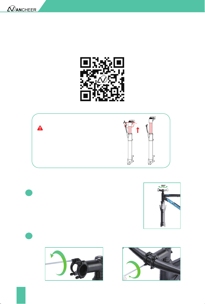
When adjusting the handlebar or saddle, please be careful not to exceed the
safety line markings on the handlebar and saddle.
When using the motor, please be careful not to hit vigorously and keep the
rotating shaft lubricated.
IMPORTANT SAFETY INSTRUCTION
●
●
●
●
●
●
●
●
●
●
●
●

02
IMPORTANT SAFETY INSTRUCTION
Try to avoid riding in severe weather such as heavy rain and snow.
It is not allowed to exceed the maximum load of the vehicle body when riding
(the maximum load is 120KG).
It is suitable for people of 16+ years old and physically fit adults, and it is strictly
forbidden to drive electric bicycles on the road by people under 16 years old.
Slow down when riding in rain or snow since the the braking distance will be
increased in such slippery conditions.
●
●
●
●

03
GENERAL INFORMATION
1. About ANCHEER Electric Bike
ANCHEER electric bike is a leading icon of e-bikes. For years, ANCHEER has been not
only dedicating to innovation, cutting-edge technology and premium materials, but
also providing cost effective e-bikes, to satisfy riders' various needs of transportation
and even desire of exploring sports & outdoors life. Just ride freely with ANCHEER !
2.What’s In the Box (Parts List)
Description Quantity
ANCHEER Electric Bike
Pedal
Reflector
2
1
User Manual
Saddle 1
1
Key
Saddle Tube 1
2
Charging Adapter
Kickstand
1
1
1
Battery
Quick Release Skewer
Tools Bag
1
1
1

04
GENERAL INFORMATION
3. Bike Components
1
2
3
4
5
9
1112
13 14
10 678
15 16 17 18 19 20
2
1
3
4
5
6
7
8
9
10
11
13
12
14
15
16
17
18
19
20
Rim
Flywheel
Front Fork
Chain
Tyre
Rear Derailleur
Head Light/Front Light
Stem Front Derailleur
Frame Chain Wheel
Battery Crank
Saddle Post/ Seat Tube Front Disc Brake Caliper
Saddle Wheel Reflector
Seat Post Clamp/ Seat Clamp Disc
Rear Disc Brake Caliper

05
GENERAL INFORMATION
21 28
29
30
31
32
22
23
24
25
26
27
23
22
24
25
26
27
29
28
30
31
32
Left Brake Lever Motor
Front Derailleur Handle Right Grip
Left Grip Right Brake Lever
Meter Throttle/ Twister
Pedal Rear Shifter
Kickstand Handle Bar
21

06
4. Tool List
5. Standover Height
For the sake of safety and comfortable riding, when the rider stands on the ground
there should be clearance of 78cm/31in from ground to the crotch of the rider. Also, at
least 3-8cm/1-3in between the crotch and the top tube of the bike.
Standover height does not apply to bicycles with step-through frames. Instead, the
limiting dimension is determined by saddle height range. You should adjust your
saddle position without exceeding the limit line on the saddle tube.
Note
GENERAL INFORMATION
Tool bag 0.12 inch (3mm)
Allen Key
0.16 inch (4mm)
Allen Key
0.20 inch (5mm)
Allen Key
Phillips-Slotted
Head Screwdriver
10-12 Open
End Wrenchr
13-15 Open
End Wrench

07
BIKE USAGE
Before Riding
During Riding
Before riding the bike on the open road, try all the settings on the electric bike, and
get used to various results in a safe and controllable environment.
Please check the power circuit, lighting circuit, and test the brake system before cycling.
Always check the tire pressure before starting to ride, and make sure that the tire is
inflated to a pressure within the specified range.
In order to ensure the safety of riding, please check regularly for loose parts or screws.
The places that need to be checked include but not limited to the seat tube, wheels,
handlebars and pedals.
If necessary, please confirm whether the battery capacity can meet you riding
demand.
2.
1.
If the pressure exceeds the recommended maximum value, the tire may blow
out of the rim, which may damage the bicycle and cause injury to the cyclist
and nearby people.
If the pressure is too low, the wheel may be damaged, or the inner tube may
be squeezed, causing the tire to leak air.
Please wear helmets and riding gear that meet the requirements in accordance with
regulations.
Avoid traveling in severe weather such as heavy rain and snow,etc.
Carry people or objects in accordance with the requirements of laws and regulations,
and the load of the entire bike should not exceed 120kg.
Obey the traffic rules.
●
●
●
●
●
●
●
●
●
After Riding
After heavy use, do not touch the hot surface, such as the disc brake rotor or the side
edge of the brake rim.
When folding the kickstand, always make sure that the stand is secure and the base is
firm to prevent the bicycle from falling.
If the bicycle is splashed with moisture, please wipe it dry and clean in time.
●
●
●

08
1. Install The Handlebar
Open the package of the bike, take out the electric bike and all the parts inside and use
the tool to cut off the packing rope. Please follow our YouTube channel- ANCHEER
SPORT, we have provided installation tutorial.
Turn the stem 180° to the forward direction, also make
sure the front fork also rotates 180° horizontally, then
both the stem and the fork bridge of the front fork are
facing forward.
INSTALLATION AND ADJUSTMENT
1.1
1.2 Using the hex key from tool kit to loosen the four screws and put the handlebar
into the stem in balance and tighten the screw.
Installation Video
When cutting the zip ties fastened on the
shock absorber of the front fork, please
be careful and don't be too close to the
shock absorber to avoid being hurt by
absorber bouncing.
NOTICE!

09
INSTALLATION AND ADJUSTMENT
2. Install The Seat
2.1
2.2
1.4
2.3
First attach the reflector to the seat tube and tighten the
screws of the reflector.
Install the saddle tube into post receiver. Set right its position and adjust height to
fit your ridding habit. (Note: please be careful not to exceed the limit line) Tighten
the fastening nut clockwise first, and then fasten the seat tube clamp.
If you find the handlebar is not in the right direction, loosen the top screw,
adjust the angle of the handlebar to keep it in horizontal direction, then
tighten the top bolt.
Adjust the seat angle to the most comfortable position.
1.3 Adjust the angle of the stem to ensure that the handlebar is level, and use the
tool to lock one screw on top and two screws on the size.

10
4.2 Using the wrench to loosen the fixing rod of the front fork and remove it (this
accessory is to prevent the front fork from being deformed during delivery but
not a needed part for the installed bike).
INSTALLATION AND ADJUSTMENT
3. Install The Front Disc Brake
4. Install The Front Wheel
Align the two screw holes of the front disc brake with the screw holes of the front
fork, and tighten the screws clockwise.
4.1 Flip the e bike upside down. Pad the
handlebar with foam to protect the
components on it from being scratched
or broken.
Figure 4.1
Figure 4.2
4.3
4.4
Take out the quick release from the small carton of your bicycle.
Slide the wheel into the fork dropout slots. Insert the disc rotor into the center of the
disc brake at the same time you are inserting the wheel axle into the fork drop out.
Figure 4.3

11
INSTALLATION AND ADJUSTMENT
4.7
4.6
4.5
Thread the adjustment nut back onto the skewer, but do not tighten too far. Figure
4.3
Slide the outer spring over the end of the skewer. Figure 4.3
Unscrew the adjustment nut from the skewer, remove outer spring and slide the
skewer through the front wheel axle so the quick-release lever is on the same side
of the chain. Figure 4.3
Note: The smaller end of the spring should be in towards the wheel.
4.8
4.9
4.10
Re-check that the handlebars are perpendicular to the front wheel. Adjust if
needed.So you can adjust the distance A=distance B. Figure 4.4
Move the quick-release lever into the open position. With one hand on the quick
release lever and one hand on the adjustment nut, start to hand tighten the
adjustment nut until you start to feel some resistance against the fork. Figure 4.4
Try to close the quick-release lever. If it closes easily, open it up and tighten the
adjustment nut further. If it is too difficult to close, open the quick-release lever
up and loosen the adjustment nut a little and try again. Figure 4.4
NOTE: Do not attempt to tighten by turning the quick-release lever. The quick-
release lever is for closing, the adjustment nut is for adjusting the tension.
Figure 4.3
Outer
spring
Adjustment
nut
Front Fork
Skewer
Inner spring
Quick-release
lever
Disc
rotor
Caliper

12
INSTALLATION AND ADJUSTMENT
5. Check The Front Wheel Rotates Smoothly
5.1 After installing the front wheel, rotate it to see whether it rotates smoothly.
If the disc brake rubs, please adjust the brake.
NOTE: Make sure the wheel is in the middle of the fork. Length A= lenght B
Quick release
Attention:
Tighten the quick release
with the adjustment nut
only!
lever in the
closed position
Quick release
lever in the open
position
AA = B B
Figure 4.4
Important! You should feel resistance when you close the quick-release lever
that should leave a temporary impression on your fingers. Open and close the
handle to ensure the wheel is securely locked in place.

13
INSTALLATION AND ADJUSTMENT
5.2 Brake Adjustment
If the brake is not sensitive, loosen
the anchor bolt of the brake cable to
shorten the brake distance of the brake
cable and then tighten the bolt. Or,
lengthen the distance of the brake cable
when the brake is too sensitive.
If the rotor always rubs against the
brake pad or the gap is too large,
loose the two centering adjustment
screws, but do not remove them.
Slowly rotate the wheel and check
the space between the rotor and
the brake pad; adjust the position
of the brake pad and the rotor.
Centering the rotor and the pads to
avoid friction. After the adjustment
is complete, tighten the screws.
Ensure that the brake cables are properly inserted into the brake levers before aligning
a mechanical disc brake. If the disc rotor is bent or damaged, replace the rotor first.
Leave the same clearance on
both sides of the disc rotor
Brake pad
Disc rotor
Adjust caliper to
center the rotor
Centering
adjustment screws
●
●

14
INSTALLATION AND ADJUSTMENT
6. Install Kickstand
7. Install The Headlight
8. Install The Pedals
Unscrew the screw in the kickstand, and install the kickstand. Then tighten with tool.
Loosen the screw on the fork with the hex key. Put the light in this position. Tighten
the screw that secures the light.Then connect the plug when the arrow on the plug
surface is aligned with the arrow.
Ensure that the thread of each pedal is fully inserted into the crank arm. Tighten the
pedals completely with a wrench. (Counterclockwise screw the pedal marked "L" on
the left side crank. Clockwise screw the pedal marked "R" on the right side crank.)

15
INSTALLATION AND ADJUSTMENT
9. Install LCD Meter
10. Install The Battery
Loosen the screw on the back of the meter with the hex key, then install the meter
on the right side of the handlebar.Tighten the screw, and connect the connector of
the meter.
Push the battery into the battery support until it is closely connected to the
socket on the pipe of the frame battery support.
Then insert the key and turn the key to lock it.
10.1
10.2

16
11. Adjust Angle Of Brake Lever, Meter, Gear Shifter, Throttle And
Louder Controller On Handlebar, Then Tightens Them With
Tools.
Shifting Recommendations
In order to increase the range, we recommend shifting according to the speed.
So far, congratulations! You have completed the assembly of the entire bike.
For starting and low-speed riding, it is best to use a low-speed gear.
At higher speeds, a higher gear should be selected.
●
●
INSTALLATION AND ADJUSTMENT
Please inflate the tire, maintain
proper tire pressure before use.
NOTICE!

17
METER OPERATION
1. Product Name
2. Appearance And Dimensions
Intelligent LCD display for e-bike.
Fig. 2-2
Top View of Display Dimensions
Fig. 2-3
Side View of Display Dimensions
Fig. 2-1 Picture of Display

18
Display provides a variety of functions to meet the riding needs of users, including:
There are three buttons on the operating unit of display YL81C, i.e., the on/off
button , plus button and minus button .
3. Meter Function
3.1
3.2
3.3
Function Overview
Functional Area Layout
Button Definitions
Battery level indicator
Assist level adjustment and indication
Headlight indicator
Speed indicator (including real-time speed, maximum speed (MAXS) and
average speed (AVG))
Mileage indicator (including total mileage(ODO) and trip distance (Trip))
Error code indicator
Parameter setting function
●
●
●
●
●
●
●
METER OPERATION
Battery level indicator
Headlight indicator
Average speed indicator
Distance/speed unit
Metric system: km, km/h
Imperial system: mile,
Speed unit Metric
system: km/h Imperial
system: MPH
Speed indicator
Assist level indicator
Maximum speed
Trip distance indicator
ODO
Table of contents
Other Ancheer Bicycle manuals

Ancheer
Ancheer AM001908 Specification sheet

Ancheer
Ancheer AM001907 User manual

Ancheer
Ancheer AMA005639 User manual

Ancheer
Ancheer AMA005637 Specification sheet

Ancheer
Ancheer AMA005757 Specification sheet

Ancheer
Ancheer E-bike User manual

Ancheer
Ancheer AM004142 Specification sheet

Ancheer
Ancheer AMA005685 Specification sheet