2. User instruction Normal pulling: 4
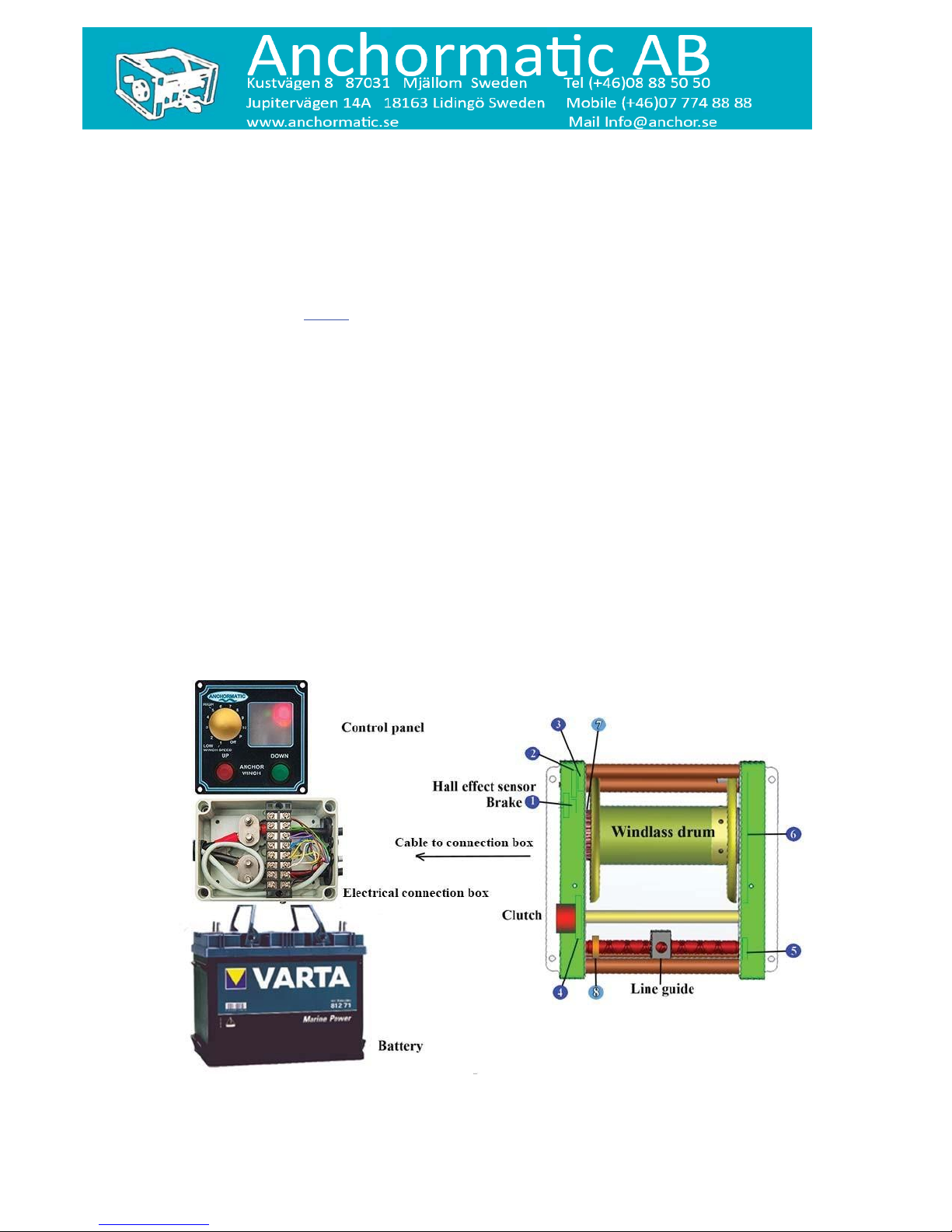
Control panel 710 1. The band drum is locked. Indicator lamps areoff.
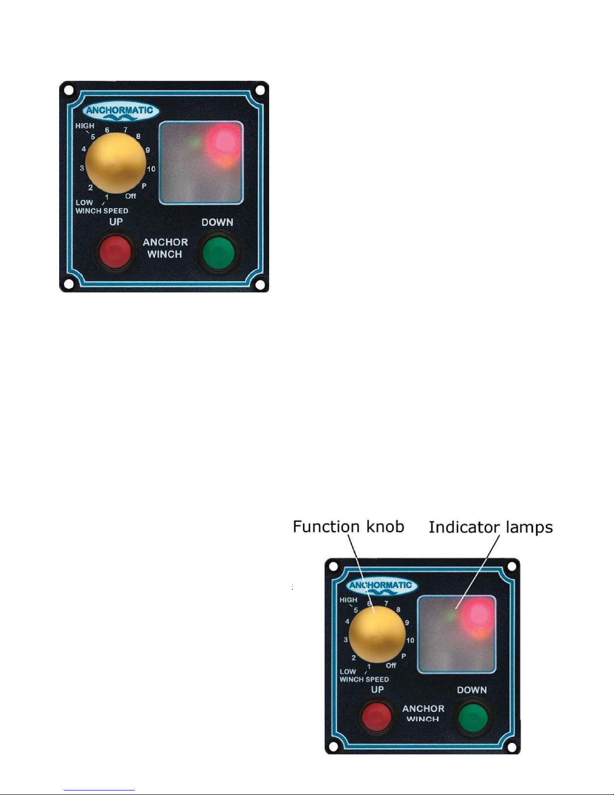
2. Turn function knob to either of positions 1-5.
1 = lowest and 5 = highest Pulling speed. Red indicator
lamp is lit.
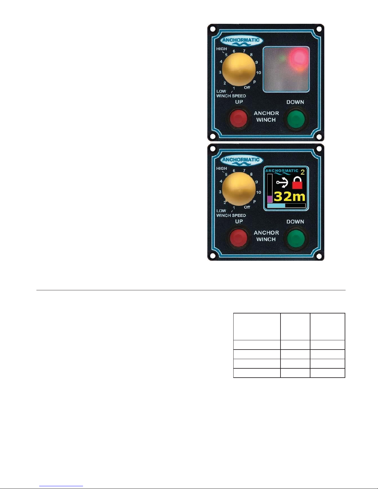
3. Push the button “UP”. Red indicator lamp flashes
quickly.
4. When the anchor reaches rinse position, the green
and yellow indicator lamps are flashing continuously.
Release the button “UP”.
5. When the anchor is to be placed in its transport posi-
tion, push the button “UP”. Red indicator lamp flashes
slowly.
6. When the anchor has reached its transport position
the green indicator lamp is lit.
7. Turn the function knob to position “OFF”. The cur-
When the function knob is set to “Off” the cur-
rency is turned off, indicator lamps are off and the
windlass is locked.
Normal anchoring:
1.
Indicator lamps are off. The anchor is in trans-
port position. The windlass is locked.
2.
Turn function knob to either of positions 1-5.
Green indicator lamp is lit continuously.
3.
Push the button “DOWN”. The anchor runs out.
Red indicator lamp flashes quickly.
IMPORTANT! When the button “DOWN” is
pushed and the rode (band) is released and runs
out one should not push the button “UP” before
the anchor has reached the bottom. The clutch
might be damaged by the force of the outgoing
anchor.
4.
When the anchor has reached the sea bottom, the
red indicator lamp is lit. Push the button “UP”. The
windlass is now locked.
5.
Turn function knob to position “OFF”. The
currency is now turned off and the band drum is
locked.
IMPORTANT! It is obligatory to push the but-
ton “UP” before you turn the function knob to
position “OFF”.
rency is now turned off and the band drum is locked.
Practical tip! When the anchor is pulled, you ought to
start the pulling with the function knob in position “1”.
Move the function knob to a higher value, “2”, “3” up
to “5” the further out the boat moves. When the rode is
pointing straight down, release the button “UP” and let
the boat move to try to free the anchor from the bottom.
Push the button “UP” till the anchor stops in rinsing po-
sition.