Anderson LeakTrac Wireless 2400 User manual


2
2885 Country Drive #190 · St. Paul, MN 55117 · 800-348-1316 · www.leaktools.com
FCC Statements
This equipment has been tested and found to comply with the limits for a Class B
digital device, pursuant to part 15 of the FCC Rules. These are designed to pro-
vide reasonable protection against harmful interference in a residential installa-
tion. This equipment generates, uses and can radiate radio frequency energy
and , if not installed and used in accordance with the instructions, may cause
harmful interference to radio communications. However, there is no guarantee
that interference will not occur in a particular installation. If this equipment does
cause harmful interference to radio or television reception, which can be deter-
mined by turning the equipment off and on, the user is encouraged to try to cor-
rect the interference by one or more of the following measures:
- Reorient or relocate the receiving antenna.
- Increase the separation between the equipment and receiver.
- Connect the equipment into an outlet on a circuit different from that to
which the receiver is connected.
- Consult the dealer or an experienced radio/TV technician for help.
CAUTION STATEMENT:
Modification to this equipment not expressly approved by the manufacturer could
void the user’s authority to operate this equipment.

3
2885 Country Drive #190 · St. Paul, MN 55117 · 800-348-1316 · www.leaktools.com
Principle of the LeakTrac 2400:
When an electrical charge is placed into the water of a vinyl lined swimming pool
(or other containment vessel that has electrically insulating walls) the electricity
will seek to make a connection to ground. The electrical current flow from the in-
put float, to the point of the ground connection will create a detectable current
path in the water. We call this detectable electrical current path a “Leak Track”.
The sophisticated LeakTrac 2400 detects these “Leak Tracks”, by measuring the
differential voltage potential at different points in the pool, and translates this in-
formation into audible clicking sounds that increase in frequency as the voltage
differential increases.
When the LeakTrac probe is aligned with current flow a rapid clicking is pro-
duced. When it is not aligned the clicking decreases or stops altogether. As the
probe is moved toward the point of low resistance the “Leak Track” becomes
more focused creating a greater differential voltage and a more rapid clicking.
The operator uses the clicking sounds to effectively pinpoint low resistance con-
nections from inside the pool to ground.
Leak Track
4
2885 Country Drive #190 · St. Paul, MN 55117 · 800-348-1316 · www.leaktools.com
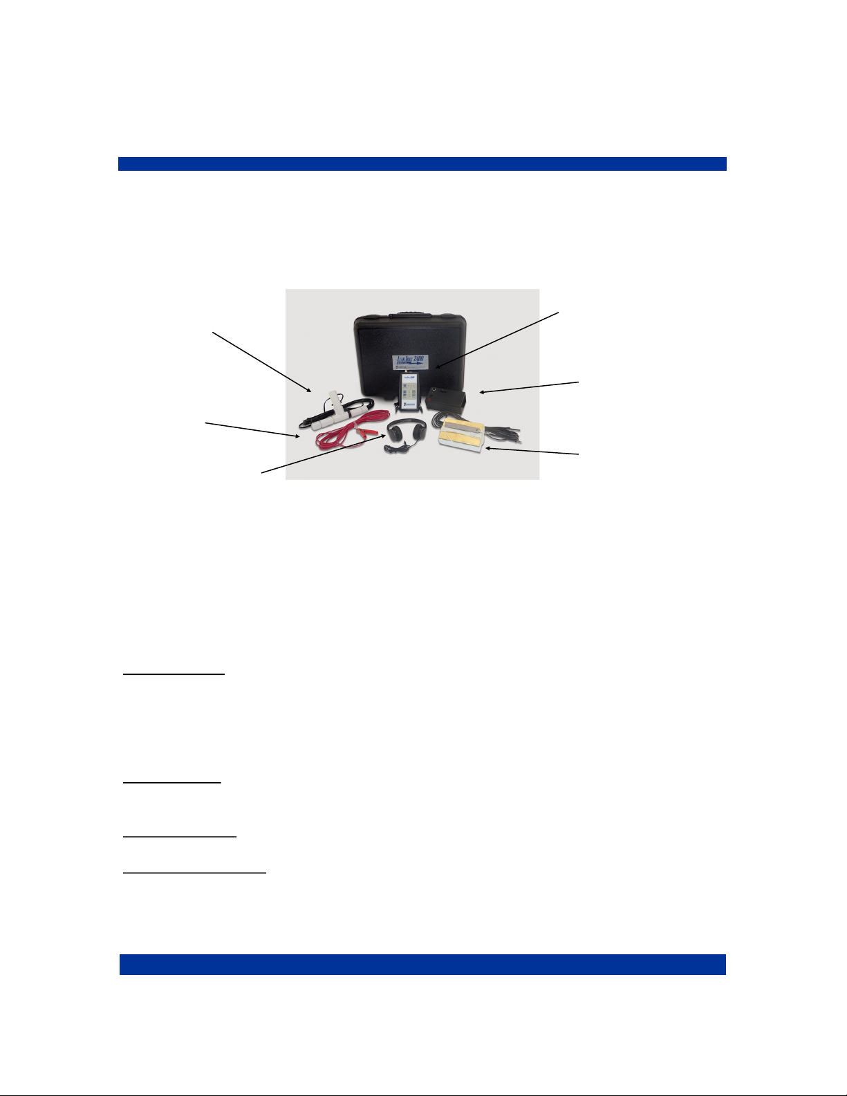
LeakTrac 2400 Component List:
The LeakTrac 2400 consists of 7 components all of which are contained in a
foam lined plastic carrying case.
Signal
Processing Unit
Probe
Ground Cable
Headphones
Power Booster
Input Float
The Signal Processing Unit (SPU)
This is the “brains” of the system, it converts input from the sensor probe into the
audible clicking sound used for leak finding. An adjustable strap allows this to be
worn around the operator's neck.
Touch pad buttons and LED indicators offer the following user interface:
SENSITIVITY Use the up arrow button to toggle through three different input am-
plification settings. Current setting will be indicated with led lights. HIGH amplifi-
cation is generally used for long distance leak detecting in order to find the gen-
eral area of the leak. MID and LOW setting are used for pinpointing the leak once
a general area is determined.
CLICK RATE Use the up and down arrows to adjust the base click rate. The unit
will return to a pre-set click rate each time it is turned off.
TRAC Indicator lights when the probe is aligned with current flow in pool.
LOW BAT Indicator lights when batteries should be replaced.

5
2885 Country Drive #190 · St. Paul, MN 55117 · 800-348-1316 · www.leaktools.com
The back of the SPU has three input/output jacks:
1. PROBE - accepts the phone plug from the sensor probe.
2. BOOSTER - accepts the locking connection from the Optional Booster
Patch Cable. This connection is used only in the event of interference with
the radio frequency link between the Booster and the SPU.
3. HEADPHONES - accepts headphone jack. The speaker in the unit shuts
off when headphones are plugged in.
The Power Booster:
This 3” x 6” x 1-1/2” black plastic box contains the AA batteries and circuitry re-
quired to provide an appropriate voltage between the pool water and ground. To
protect the unit and the internal antenna the booster should be kept in the foam
lined case.
The power booster has two input/output jacks:
1. Red - accepts the banana plug connector from the red
Ground Cable.
2. Black - accepts the banana plug connector from the Input
Float Cable.
A toggle switch turns the Booster on ( I ) and off ( 0 ). A LED indicator lights
when the unit is communicating with the SPU. To conserve batteries, the
Booster will turn off automatically when it does not receive a signal from the
SPU for one minute. To re-set the connection flip the toggle to off then on again.
Although the unit reverts to a “sleep” mode when the SPU is turned off, the
toggle switch should be moved to the off position for storage and transport to
conserve batteries.
The Sensor Probe:
This “T” shaped PVC assembly picks up the electrical current flow from the water.
The probe attaches to a standard telescoping pole to allow surveying all parts of
the pool. Twenty feet of wire extends from the probe to the phono plug.
Probe extension caps cover the ends of the probe to reduce random signal read-
ing that result from water flow over the electrodes.
6
2885 Country Drive #190 · St. Paul, MN 55117 · 800-348-1316 · www.leaktools.com
The Input Float:
This brass plate attached to a block of Styrofoam floats in the pool and puts the
charge into the water. A length of insulated wire to the black banana plug is used
to connect to the black input jack on the Power Booster
A lead weight provides a means for anchoring the float in its desired position.
The Ground Cable:
This clamp is used to make a connection to ground. A length of insulated wire to
red banana plug is used to connect to the red input jack on the Power Booster.
Headphones:
These standard headphones plug into the back of the Signal Processing Unit.
What Makes a Good Leak Track
Three factors contribute to the quality of the “Leak Track” and your ability to de-
tect it with the LeakTrac 2400.
1. Difference in conductivity of the pool shell in comparison to the point of low
resistance.
The LeakTrac 2400 does not work well in concrete pools
because the concrete itself conducts electricity to the
ground almost as well as a leak does.
One weak “Leak Track”

7
2885 Country Drive #190 · St. Paul, MN 55117 · 800-348-1316 · www.leaktools.com
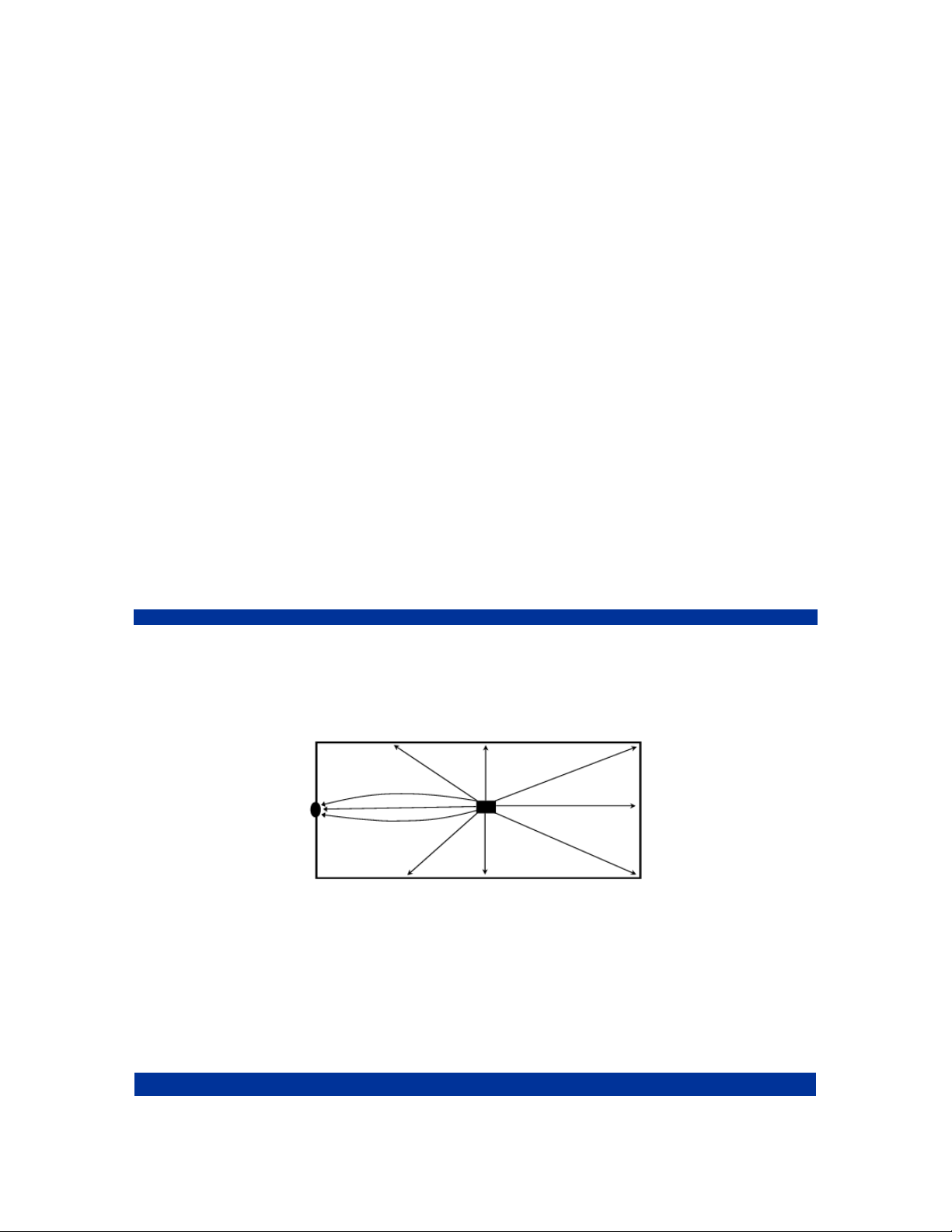
2. Number of points of low resistance in the pool.
Five “Leak Tracks”
Since there is only a limited amount of charge going into the pool
the strongest “Leak Track” will be produced when there is
only one path for the charge to connect to ground.
3. Relative conductivity of different points of low resistance.
One weak “Leak Track” - One Strong “Leak Track”
A highly conductive connection to ground will take more
current flow and thus produce a stronger “Leak Track” than a less
conductive point of low resistance in the same pool.

8
2885 Country Drive #190 · St. Paul, MN 55117 · 800-348-1316 · www.leaktools.com
Leaks are often not the only low resistance paths from inside a pool to ground.
Other metallic connections such as light niches, fitting screws and even grounded
equipment such as the pool heater may produce “Leak Tracks.” Testing has
shown the following ranking of common connections to ground from lowest elec-
trical resistance to highest. Leaks generally fall in the upper end of this ranking
depending on size.
To use the LeakTrac 2400 most effectively it is necessary to create the strongest
possible “Leak Track” going to the leak, while eliminating or disregarding other
connections to ground that are not leaks.
Finding Leaks with the LeakTrac 2400
Preliminary Steps:
Before using the LeakTrac 2400, first confirm that there is indeed a leak in the
pool by using the Leakalyzer or doing a bucket test. Next, pressure test the
plumbing lines and repair any leaking lines. Finally, dye test around the lights,
return fittings, skimmers and stair gaskets to assure these areas are not leaking.
(If you are unfamiliar with the bucket test, proper pressure testing, or dye testing
visit www.leaktools.com.)
Pool Preparation:
1. Make sure pumps and equipment are turned off and the pool is filled to its
normal level, assuring that all leaks are underwater.
2. Remove any automatic cleaning devices that may get tangled in the Leak-
Trac 2400 probe or cables.
High
Low
Conductivity
LEAKS
1. Metal light niches
2. Ladder
3. Some stair anchor screws that extend to ground
4. Main drain
5. Return and skimmer fitting screws
6. Water through pipes to grounded equipment
7. Thin spots in liner

9
2885 Country Drive #190 · St. Paul, MN 55117 · 800-348-1316 · www.leaktools.com
3. Remove any conductive connections from inside the pool to ground. This
includes ladders, thermometers, vacuum poles leaning up against the coping,
or wet pool covers that extend from the water to the ground. If you cannot re-
move ladders, a plastic trash bag can be put over the ladder, effectively
insulating it from the pool water.
4. Cover any lights with the light cover provided. Place the cover over the light
with the rubber gasket against the pool wall and the hose connections at the
bottom. Keep the two hoses above water level. To get the cover to make an
initial seal you may need to trap some air in the cover. This is done the same
way a diving mask is cleared, by holding the top of the cover against the pool
wall and blowing through the hose without the pump. Once a seal is made
pump some of the water out of the inside of the light cover with the hand
pump. One or two pumps should be enough to get the cover to stay. Howev-
er, you may wish to pump all of the water out to provide a better seal and
more effective electrical insulation of the light. The hoses must be left above
water level, but not plugged, for proper seal. The cover can be removed by
placing the hose without the pump into the water below the bottom edge of
the cover.
Warning: This light cover is not intended for any use where the
rubber inner tube gasket contacts the vinyl pool wall for over 2
hours. Oils in some vinyl liners may attack the rubber gasket causing
permanent discoloration to the liner. If extended use is required,
cut a piece of scrap vinyl to put between the pool wall and gasket.
5. Depending on the pool, fitting screws (especially at skimmers and main
drains) can be connections to ground which create confusing Leak Track
signals. With experience you will learn to disregard these signals (you should
have also already dye tested these areas, eliminating them as a potential
leak). Simple methods of covering the fittings can be used if elimination of the
signal is preferred. Skimmer and return fitting screws can be covered with
small suction cups (used for hanging signs on windows). The main drain can
be covered using the Light Cover modified with longer hoses. An attachment
that allows the Light Cover to be positioned over the main drain using your
telescoping pole is available from Anderson Mfg. Co.
Note: In most cases plugging return fittings and main drains to eliminate
connections back to the grounded equipment is unnecessary. Instead of
eliminating these connections, it is possible to disregard the relatively
weak “Leak Track” signal they produce.

10
2885 Country Drive #190 · St. Paul, MN 55117 · 800-348-1316 · www.leaktools.com
Set-up of The LeakTrac 2400
1. Look for a place to set up your LeakTrac 2400 that has a convenient connec-
tion to ground within 20 feet. Open the case and remove all components ex-
cept the Power Booster.
2. Plug the red banana plug from the Ground cable into the red socket of the
Power Booster and attach the clamp to ground.
Good connections to ground include:
Ladder anchors sockets
Diving board anchor bolts
Metal junction box conduit
Any metal rod stuck into the ground
If the ground you choose is painted, you
must scrape through the paint to assure an electrical connection is made with the
ground clamp.
3. Plug the black banana plug from the Input Float into the black socket on the
Power Booster. Unwind enough anchor cord to allow the float anchor to touch
the bottom of the pool and toss the anchor and float into the pool so that the
brass side of the float is down.
Table of contents


