AndyMark am-5000 User manual

October 2023
Assembly Guide
CENTERSTAGE Robot

2
CENTERSTAGE Robot
AM Part Name
AM Part #
Quantity
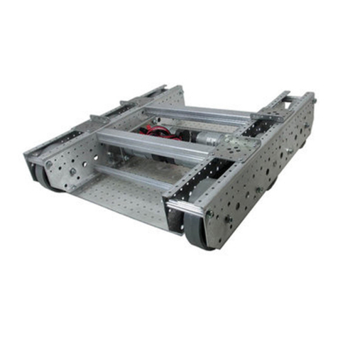
Robits Starter Drive Base
See Separate Instructions
1
Robits 0.5×0.5×2.0 Tube
am-5001-0200
3
Robits 0.5×0.5×4.0 Tube
am-5001-0400
1
Robits 0.5×0.5×6.0 Tube
am-5001-0600
2
Robits 0.5×0.5×8.0 Tube
am-5001-0800
2
Robits 0.5×0.5×16.0 Tube
am-5001-1600
2
Robits 1.0×1.0×15.5 Tube
am-5002-1550
2
Robits Angle Gusset (135°)
am-5010_135
2
Robits 1×8 Beam
am-5011_1x8
1
Robits 1×12 Beam
am-5011_1x12
1
Robits 3×3 Corner Gusset
am-5005_3x3
4
Robits 5×5 Corner Gusset
am-5005_5x5
3
Robits 2×4 Plate
am-5006_2x4
1
Robits 4×4 Plate
am-5006_4x4
1
NeveRest Orbital - 50.9
am-4609b
1
Robits 80-100T Motor Mount
am-5017
1
6mm D to 375IN Hex-Shaft Adapter
am-3444
1
Programmable Servo Torque
am-4954
2
5mm Hex to 375IN Hex Shaft Adapter
am-4957
2
Robits Bushing for 0.375 Hex
am-5021
2
Required Tool List
AM Part Name
AM Part #
Hex Driver, Ball End 2.5mm with Handle
am-3724
Hex Driver, Ball End 3/32" with Handle
am-3173
Hex Driver, Ball End 5/32" with Handle
am-2751
3/8 Combination Wrench
am-4961

3
AM Part Name
AM Part #
Quantity
Robits Side Shaft Carrier
am-5015
1
Robits Double End Shaft Carrier
am-5016
4
40 Tooth 20DP 0.375 in. Hex Bore Plastic Gear
am-5020_40
1
60 Tooth 20DP 0.375 in. Hex Bore Plastic Gear
am-5020_60
1
Robits 0.375 in. Hex Shaft 10 in. Long
am-5003-1000
1
2 in. Compliant Wheels (Green)
am-3571_green
2
10-32 Nylock Jam Nut
am-1063
58
Spacer, 0.375 OD x 0.194 ID x 0.25 Long Nylon
am-1700
10
Spacer, 0.375 OD x 0.194 ID x 0.50 Long Nylon
am-1697
4
Spacer, 0.375 OD x 0.194 ID x 0.75 Long Nylon
am-4107
3
Spacer, 0.375 OD x 0.194 ID x 1.00 Long Nylon
am-1696
3
Screw, SHCS, 10-32 x 0500
am-1002
6
Screw, SHCS, 10-32 x 0750
am-1047
9
Screw, SHCS, 10-32 x 1000
am-1056
16
Screw, SHCS, 10-32 x 1250
am-1041
11
Screw, SHCS, 10-32 x 1500
am-1014
20
Screw, SHCS, 10-32 x 1750
am-1048
13
Screw, SHCS, 10-32 x 2000
am-1049
3
M3-0.5 x 8 mm Socket Head Cap Screw with Thread Patch
am-1500
3
#10 Steel Washer
am-1026
4
Spacer, 0.430 ID x 0.500 OD x 0.250 Long Aluminum
am-1698
5
Spacer, 0.430 ID x 0.500 OD x 0.500 Long Aluminum
am-1699
8
10-32 Female Threaded 1 in. Long 0.375 in. Round Standoff
am-1701
4
10-32 Female Threaded 2 in. Long 0.375 in. Round Standoff
am-1702
4
10-32 Female Threaded 4 in. Long 0.375 in. Round Standoff
am-1704
1
Rubber Bands #33, Black
am-5024_black
Varies
Cable Ties 4 in
am-1589_black
2
15.5×6×1/32 Perforated PC
am-4964
2

4
The AndyMark CENTERSTAGE Robot uses the Robits Starter Drive Base. Instructions for how to
build the starter drive base can be found on the AndyMark website.
Part 1: Build the Tower
Chassis

5
Use the following steps to build the right upright on the right drive module.
1. Place one 135° gusset (am-5010_135) on the right drive rail and secure with two 10-32 x 1500
inch screws (am-1014) and two 10-32 nylock jam nuts (am-1063).
2. Locate one 0.5×0.5×6.0 Tube (am-5001-0600). Attach to the drive rail and secure with one
10-32 x 1750 inch screw (am-1048) and one 10-32 nylock jam nut (am-1063).

6
3. Install one 1 inch standoff (am-1701) to the top most hole of the 135° gusset with one 10-32 x
0750 screw (am-1047) and attach one 1 inch standoff (am-1701) to the top most hole of the 6
inch tube using one 10-32 x 1000 (am-1056) screw.
4. Install one 1.0×1.0×15.5 Tube (am-5002-1550) to the previously installed standoffs as shown
using two 10-32 x 1500 screws (am-1014).
10-32 x 1000 (am-1056)
10-32 x 0750 (am-1047)

7
Use the following steps to repeat the process and build the left upright on the other drive
module.
5. Place one 135° gusset (am-5010_135) on the left drive rail and secure with two 10-32 x 1500
(am-1014) inch screws and two 10-32 nylock jam nuts (am-1063).
6. Locate one 0.5×0.5×6.0 Tube (am-5001-0600) to the drive rail and secure with one 10-32 x
1750 screw (am-1048) and one 10-32 nylock jam nut (am-1063).

8
7. Install one 1 inch standoff (am-1701) to the top most hole of the 135° gusset with one 10-32 x
0750 screw (am-1047) and attach one 1 inch standoff (am-1701) to the top most hole of the 6
inch tube using one 10-32 x 1000 (am-1056) screw.
8. Install one 1.0×1.0×15.5 Tube (am-5002-1550) to the previously installed standoffs using two
10-32 x 1500 screws (am-1014).
10-32 x 0750 (am-1047)
10-32 x 1000 (am-1056)

9
Install Cross Connects and Corner Gussets
9. Locate two 0.5×0.5×8.0 Tubes (am-5001-0800) to the uprights and secure with four 10-32 x
1750 screws (am-1048) and four 10-32 nylock jam nuts (am-1063) each.
10.Install two 3x3 Corner Gussets (am-5005_3x3) to each 6 inch tube using two 10-32 x 1000
screws (am-1056) and two 10-32 nylock jam nuts (am-1063) each
The tower assembly is complete.

10
Part 2: Build the Arm
Assemble Arm
1. Fasten two Double End Shaft Carriers (am-5016) to the ends of one 0.5×0.5×16.0 Tube
(am-5001-1600) using two 10-32 x 1250 screws (am-1041) and two 10-32 nylock jam nuts
(am-1063).
Repeat this step to create two arm segments.
2. Connect the arm segments using one 0.5×0.5×4.0 Tube (am-5001-0400) and fasten with two
10-32 x 1250 inch screws and two 10-32 nylock jam nuts (am-1063).
x2

11
3. Install two 3x3 corner gussets (am-5005_3x3) to the side of the arm using two 10-32 x 1000
inch screws (am-1056) and two 10-32 nylock nuts (am-1063) each.
4. Connect the corner gussets using one 4 inch standoff (am-1704) using two 10-32 x 0750
screws (am-1047).

12
5. On the backside of the double end gusset, install one ½ inch long spacer (am-1697) with a few
rubber bands (am-5024_black) and one 10-32 x 1250 screw (am-1041) and one 10-32 nylock
jam nut (am-1063).
Repeat this step for a total of two counter balance assemblies.
Install Motor
6. Install one 80-100T motor mount plate (am-5017) to the outside of the 1.0×1.0×15.5 Tube
using four 10-32 x 1500 screws (am-1014) and four 10-32 nylock nuts (am-1063).
NOTE: Rubber band
quantity may need to be
adjusted depending on
team preference for arm
motion

13
7. Install one NeveRest Orbital 50.9 gearmotor (am-4609b) to the motor mount plate using three
M3-8mm patched screws (am-1500) in the three outermost mounting holes.
8. Place one 6mm to 375 Hex adapter (am-3444) on the motor shaft. Make sure to secure by
tightening the provided 10-32 set screw.
9. Slide one 40T gear (am-5020_40) and one ½ inch shaft spacer (am-1699). Retain the
assembly with the ¼ inch washer and screw provided with the adapter.

14
Install Arm
10.Insert one bushing (am-5021) into the top most hole in the tower upright.
11.Prepare one 10 inch long shaft (am-5003-1000) by fastening the end with one 10-32 x 0500
screw (am-1002) and one #10 washer (am-1026). Slide one ¼ inch shaft spacer (am-1698)
onto the shaft.
12.Move the arm into position and carefully insert the shaft assembly into the bushing on the
tower upright. The shaft will slide through spacers and the arm assembly. To get the arm
centered in the robot there will be two ½” shaft spacers (am-1699) and one ¼” (am-1698) shaft
spacer on the non-motor side of the arm and there will be three ½” shaft spacers (am-1699)
and one ¼” (am-1698) shaft spacer on the motor side of the arm.
¼” Shaft Spacer (am-1698)

15
13.Slide a bushing (am-5021) onto the shaft and into the other upright.
14.Slide one ¼ inch shaft spacer (am-1698) and one 60T gear (am-5020_60). Retain the gear
using one ½ inch shaft spacer (am-1699) and one 10-32 x 0500 screw (am-1002) and one #10
washer (am-1026).

16
Install Counterbalance
15.In the rear frame cross tube, install one 10-32 x 1500 screw (am-1014) with one ¾” screw
spacer (am-4107) spacer, one #10 washer (am-1026), and one 10-32 nylock jam nut
(am-1063).
Repeat this to make two counterbalance mounts.
16.Connect the rubber bands from the back of the arm to the counterbalance mounts on the
chassis cross tube.

17
Part 3: Build the claw
Assemble Claw
1. Install two 0.5×0.5×2.0 Tube (am-5001-0200) to one 2x4 plate (am-5006_2x4) using two 10-32
x 1000 screws (am-1056) and two 10-32 nylock jam nuts (am-1063)
2. Fasten two 5x5 corner gussets (am-5005_5x5) to the assembly using two 10-32 x 1500 screws
(am-1014) and two 10-32 nylock jam nuts (am-1063).

18
3. Fasten one 0.5×0.5×2.0 Tube (am-5001-0200) to the 5x5 corner gusset using two 10-32 x
2000 screws (am-1049), two 1 inch screw spacers (am-1696), and two 10-32 nylock jam nuts
(am-1063).
4. Install one 5x5 corner gusset (am-5005_5x5) to the assembly using the following hardware:
•On the tube side, use one 10-32 x 2000 screw (am-1049), one ¾ inch screw spacer (am-
4107), and one 10-32 nylock jam nut (am-1063) to connect the edge hole of the bracket
through the tube and assembly.
•On the non-tube side: use one 10-32 x 1750 inch screw (am-1048), one 1 inch screw
spacer (am-1696), and one 10-32 nylock jam nut (am-1063).
5. Fasten one 4x4 plate (am-5006_4x4) to the top side of the lower 5x5 corner gusset using two
10-32 x 0750 screws (am-1047) and two 10-32 nylock jam nuts (am-1063)

19
Assemble Servos and Adapters
6. Install one 5mm to 375 Hex adapter (am-4957) to the end of the servo using the provided M3 x
14mm screw.
Repeat this process to make two servo assemblies.
Install roller servo and linkage
7. Fasten one servo to the assembly using three 10-32 x 1000 screws (am-1056) with three ¼
inch screw spacers (am-1700) and three 10-32 nylock jam nuts (am-1063). The servo should
be mounted to the 5x5 corner gusset opposite the tube and standoffs with the servo shaft
facing the direction as the standoffs.
8. Turn the assembly over and slide two 2 in. Compliant Wheels (am-3571_green) onto the servo
shaft. Retain the assembly with the ¼ inch washer and screw provided with the adapter.
x2
NOTE: The roller
servo will need to be
set for continuous
rotation mode.

20
9. Loosely fasten one 1x12 beam (am-5011_1x12) to the claw using one 10-32 x 1000 screw
(am-1056) and one 10-32 nylock jam nut (am-1063).
Install Wrist Servo
Raise the arm up for access.
10.Fasten one servo assembly to the arm as shown using three 10-32 x 1250 screws (am-1041)
with three ¼ inch screw spacers (am-1700) and three 10-32 nylock jam nuts (am-1063).
NOTE: The screw should be tight
enough to minimize side to side
movement but still be loose enough to
rotate.
Other AndyMark Robotics manuals

AndyMark
AndyMark am-4671 User manual

AndyMark
AndyMark Rover am-4100 MK6 Series User manual

AndyMark
AndyMark AM14U5 User manual

AndyMark
AndyMark CIMple Box User manual

AndyMark
AndyMark AM14U4 Use and care manual

AndyMark
AndyMark TileRunner Original 6WD User manual

AndyMark
AndyMark Rover am-4100 PN8 Series User manual