Berker 75318102 User manual

30V DC
-+
Bus
auto
C6
C5
C8C8
C7C7
13 15
C5 C6
17
C7
19
C8
10 12 14 16
C5 C6 C7 C8
79
C2 C3
11
C4
468
C2 C3 C4
C2C2
C1C1
C4C4
C3C3
5
NL
C1
2
C1
L3
L2
L1
N
7531810
4
2
3
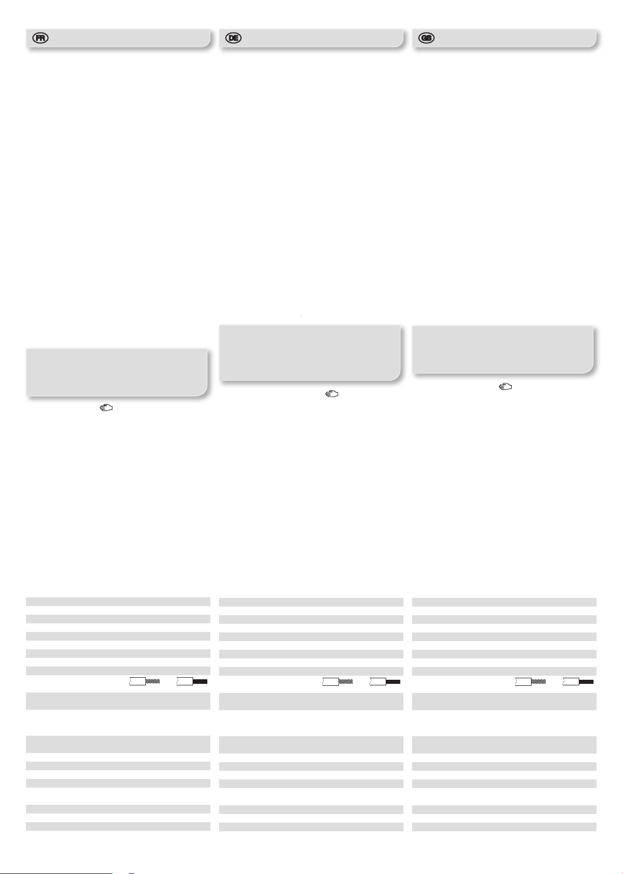
1• Commutateur Auto/Manu
• Schalter Auto/Manu
• Auto/Manu switch
2• Voyants d’état
• Kontrollleuchten
• Indicators state
3• Boutons poussoirs de commande
locale
• Taster zur lokalen Ansteuerung
• Local command push-button
4• Bouton poussoir lumineux
d’adressage physique
• Leuchttaster zur physikalischen
Adressierung
• Physical addressing lighted push
button
Les sorties peuvent être raccordées sur des phases différentes.
Die Schaltausgänge können an unterschiedliche Phasen angeschlossen werden.
The outputs can be connected to different phases.
Type de charges / Lasttyp / Load type 75318102 75318104 75318105
230 Vv
Lampes à incandescence
Glühlampen
Incandescent lamps 800 W 2300 W 2300 W
230 Vv
Lampes halogènes
Halogenlampen
Halogen lamps 800 W 2300 W 2300 W
12V v
24V DC
Transformateur ferromagnétique
Konventioneller Transformator
Conventional transformer 800 W 1600 W 1600 W
12V DC
24V DC
Transformateur électronique
Elekronischer Transformator
Electronic transformer 800 W 1200 W 1200 W
230 Vv
Tubes fluorescents non compensé
Leuchstofflampen ohne Vorschaltgerät
Fluorescent tubes non compensated 800 W 1200 W 1200 W
Tubes fluorescents pour ballast électronique (mono ou duo)
Leuchstofflampen mit EVG (mono oder duo)
Fluorescent tubes for electronic ballast (mono or duo) 12 x 36 W 20 x 36 W 20 x 36 W
Tubes fluorescents compensés en parallèle
Leuchstofflampen mit konventionellen Vorschaltgerät, Parallelschaltung
Parallel compensated fluorescent tubes
1500 W
200 µF
230 Vv
Fluo compact
Sparlampen
Compact fluorescent 6 x 23 W 18 x 23 W 18 x 23 W
1
AAttention!
• Appareil à installer uniquement par un installateur
électricien selon les normes d’installation en
vigueur dans le pays.
• Respecter les règles d’installation TBTS.
• Ne pas dépasser la charge maximale admissible
par appareil.
• Le non-respect de ces instructions peut entraîner
des dommages sur l'appareil, un incendie ou
d'autres conséquences dangereuses.
EAchtung!
• Einbau und Montage dürfen nur durch eine
Elektrofachkraft gemäß den einschlägigen
Installationsnormen des Landes erfolgen.
• Installationsvorschriften zur Schutzmaßnahme
SELV beachten.
• Die zulässige Höchstlast pro Gerät darf nicht
überschritten werden.
• Die Nichteinhaltung dieser Anweisungen kann
Schäden am Gerät, Brände oder sonstige
gefährliche Folgen verursachen.
ZCaution!
• This device is to be installed only by a professional
electrician fitter according to local applicable
installation standards.
• Conform to SELV installation rules.
• Do not exceed the maximum permissible load per
device
• Failure to follow these instructions may cause
damage to the device, fire or other dangerous
consequences.
M
Notices d’instructions
Bedienungsanleitung
Operation instructions
Réf. no./ Best.-Nr./ Order no
75318102,
75318104, 75318105
Module 8 sorties
Schaltausgang 8-fach
Output module 8-fold
Berker GmbH & Co. KG
Klagebach 38
58579 Schalksmühle/Germany
Telefon: + 49 (0) 23 55/90 5-0
Telefax: + 49 (0) 23 55/90 5-111
www.berker.com
03/2013
6T 8503-50A
azeiyr
AGarantie
Sous réserve de modications techniques et de
forme, dans la mesure où elles sont utiles au progrès
techniques. Nos appareils sont garantis dans le
cadre des dispositions légales en vigueur. Pour toute
demande en garantie, s’adresser à votre revendeur ou
retourner l’appareil dûment affranchi avec description
de défaut à notre Centre Service.
ZWarranty
We reserve the right to make technical and formal
changes to the product in the interest of technical
progress. Our products are under guarantee within
the scope of the statutory provisions. If you have a
warranty claim, please contact the point of sale or
ship the device postage free with a description of the
fault to the appropriate regional representative.
EGewährleistung
Technische und formale Änderungen am Produkt,
soweit sie dem technischen Fortschritt dienen,
behalten wir uns vor. Wir leisten Gewähr im
Rahmen der gesetzlichen Bestimmungen. Im
Gewährleistungsfall bitte an die Verkaufsstelle wenden
oder das Gerät portofrei mit Fehlerbeschreibung an
unser Service-Center senden.
Berker GmbH & Co. KG
Service-Center
Hubertusstraße 17
D-57482 Wenden-Ottngen
Telefon: 0 23 55 / 90 5-0
Telefax: 0 23 55 / 90 5-111
1Hager 07.12 6T 8503-50A1
Die 8-fach-Ausgänge 7531810x ermöglichen das
Schalten von elektrischen Lasten über den KNX-Bus.
Sie dienen der Steuerung der Beleuchtung (siehe
Lasttabelle) oder des Fenster- und Türbereichs, wie z.
B. Rollläden, Markisen, Jalousien, je nach Konfiguration
des Geräts.
Diese Geräte sind in 3 Varianten erhältlich, die sich durch
den Typ und die Leistung der anschließbaren Lasten
unterscheiden.
Funktionen
• Auswahl der Funktion EIN oder AUS oder Rollladen/
Jalousie pro Kanalpaar bei der Konguration.
• Bis zu 8 unabhängige Kanäle, gesteuert über den KNX-
Bus (je nach kongurierten Funktionen).
• Anzeige des Zustandes der Ausgänge am Produkt mit
Bus und/oder Netz (230 V).
• Möglichkeit der manuellen Steuerung der Ausgänge
über das Produkt unabhängig von der Art der
Stromversorgung (Bus und/oder Netz).
Einstellungen
• Planung, Installation und Inbetriebnahme des Gerätes
erfolgen mit Hilfe einer KNX-zertifizierten Software.
Produktdatenbank, technische Beschreibungen sowie
Konvertierungs- und weitere Hilfs-programme finden Sie
stets aktuell auf unserer Internet-Seite.
Test und Inbetriebnahme
Schalter Auto/Manu 1und Taster zur lokalen
Ansteuerung 3
Vor dem ersten Einspeichern im Handbetrieb ist
das Gerät auf Beleuchtungssteuerung eingestellt.
Falls bei dieser Betriebsart Motoren angeschlossen
werden. darauf achten, dass die Steuerbefehle
Aufwärts und Abwärts nicht gleichzeitig aktiviert
werden.
Steht der Schalter 1, auf Manu ( ), können die an die
Ausgänge angeschlossenen Lasten über die Taster 3
geschaltet werden.
Zum Kongurieren des Gerätes hat der Schalter 1 auf
Auto zu stehen. Steht der Schalter 1auf Auto sind die
Taster 3deaktiviert und die Relais lassen sich nur über
den Bus KNX ansteuern.
Kontrollleuchten 2
Die Kontrollleuchten 2geben den Zustand der
entsprechenden Ausgangsrelais an: Leuchte ein =
Relais geschlossen.
Ein Blinken aller Kontrollleuchten besagt, daß das
geladene Programm nicht mit dem Gerät kompatibel ist.
Leuchttaster zur physikalischen Adressierung 4
Drücken Sie den Leuchttaster 4um die physikalische
Adressierung des Gerätes vorzunehmen oder
das Anliegen des Busses zu überprüfen:
- Leuchte ein = Bus liegt an, physikalische Adressierung
läuft.
- Kontrollleuchte blinkt = keine Stromversorgung am
Bus.
Les pilotes 8 sorties 7531s810x sont des relais
permettant d’interfacer le Bus KNX avec des
charges électriques commandées en tout ou rien. Ils
permettent de commander de l’éclairage (voir tableau
de charges), ou des ouvrants tels que volets roulants,
stores à bannes, stores à lamelles, en fonction de la
configuration du produit.
Ces produits sont déclinés en 3 variantes qui se
distinguent par la puissance et le type des charges
raccordables.
Fonctions
• Sélection de la fonction tout ou rien ou volet/store
par paire de voies lors de la configuration.
• Jusqu'à 8 voies indépendantes commandées par le
Bus KNX (selon fonctions configurées).
• Visualisation de l’état des sorties sur le produit avec
présence bus et/ou présence secteur (230V).
• Possibilité de commande manuelle des sorties à
partir du produit quelque soit le type d'alimentation
(bus et/ou secteur).
Configuration
• La programmation, l`installation et la mise en service
de l`appareillage s`effectuent à l`aide d`un logiciel
certifié KNX.
La base de données produit, les descriptions
techniques, les programmes de conversion ainsi
que les d`autres programmes d`aide actualisés sont
disponibles sur notre site Internet.
Test et mise en service
Commutateur Auto/Manu 1et boutons poussoirs
de commande locale 3
Avant le premier téléchargement, en mode manuel,
le produit est configuré en commande d'éclairage.
Dans ce mode, si un ouvrant est câblé, veiller à
ne pas activer les commandes de montée et de
descente simultanément.
En position Manu ( ) du commutateur 1, les
boutons poussoirs 3permettent de commander les
charges raccordées aux sorties. Utilisez la position
Auto du commutateur 1en mode exploitation ou pour
congurer le produit. En position Auto du commutateur
1les boutons poussoirs 3sont inactifs et les relais
réagissent aux ordres provenant du bus KNX.
Voyants d’état 2
Les voyants 2indiquent l’état des relais de
sortie correspondants: allumé = relais fermé.
Un clignotement permanent des voyants indique le
chargement d’un logiciel d’application inapproprié.
Bouton poussoir lumineux d’adressage physique 4
Appuyez sur le bouton poussoir lumineux 4pour
réaliser l’adressage physique du produit ou vérier la
présence du bus:
- voyant allumé = présence bus et produit en adressage
physique.
- Voyant clignotant = tension bus absente.
The 8-fold outputs modules 7531810x are relays
designed to interface Bus KNX with on/off electric loads.
They control lighting (see load table) or the opening
operations such as for shutters, awning blinds and
venetian blinds, depending on the configuration of the
product.
3 product versions are available according to the
power and the type of connectable loads.
Functions
• Selection of the ON-OFF function or shutter/blind for
each channel pair when conguring.
• Up to 8 independent channels controlled via the KNX
bus (depending on features congured).
• Visualization of the status of the device outputs in the
presence of the bus and/or mains (230V).
• Possibility of manual control of the outputs from the
product, whatever the type of power supply (bus
and/or mains).
Configuration
• The planning, installation and commissioning of the
device is carried out with the help of KNX-certified
software.
You can find the latest version of the product database,
technical descriptions as well as conversion and
additional support programs on our website.
Test and startup
Auto/Manu switch 1and local command
pushbutton 3
Before the rst download, in manual mode, the
product is congured for lighting control.
In this mode, if an opening operation is wired, be
careful not to activate the up and down commands
simultaneously.
With switch 1in Manu () position, push buttons
3control loads connected to outputs.
Use Auto position of switch 1in operating mode or
to configure the product. In Auto position of switch 1
push buttons 3are inactive and relays are controlled
by commands from the KNX bus.
State indicators 2
Indicators 2display the respective of corresponding
output relays: indicator on = closed relay.
Continuous flickering of indicators indicates loading of
wrong application software.
Physical addressing lighted push button 4
Press lighted pushbutton 4to perform physical
addressing of the product or to verify the bus presence:
- switched on indicator = bus presence and product in
physical addressing.
- Flashing indicator = No power to bus.
A E Z
26T 8503-50A
Caractéristiques techniques
Tension d’alimentation 30 V DC TBTS
Dissipation maximale 2 W (8x4A), 12 W (6x16A)
Consommation typique sur le bus KNX 15,2 mA
Consommation au repos sur le bus KNX 8,6 mA
Consommation typique bus KNX avec secteur 2 mA
Consommation bus KNX au repos avec secteur 2 mA
Encombrement 6 x 17,5 mm
T° de fonctionnement -5°C —> + 45°C
T° de stockage - 20°C —> + 70°C
Raccordement
12 % noir
0,75 mm2—> 2,5 mm2
Pouvoir de coupure µ230Vv4A AC1 (75318102)
µ230Vv16A AC1 (75318104/75318105)
Intensité maximale admissible par appareil
(somme C1…C8) max. 32A (75318102)
max. 80A (75318104/75318105)
Cadence de commutation maximale à pleine charge
6 cycles de commutations / minute
Mode d'installation Rail DIN
Altitude de fonctionnement < 2000 m
Degré de pollution 2
Tension de choc 4 kV
Indices de protection IP 20 (boîtier) /
IP30 (boîtier sous plastron)
IK 04
Catégorie de surtension III
Norme EN50491-3 ; EN60669-2-1
Technische Daten
Versorgungsspannung 30 V DC SELV
Verlustleistung 2 W (8x4A), 12 W (6x16A)
Typischer Eigenverbrauch am KNX-Bus 15,2 mA
Eigenverbrauch im Ruhezustand am KNX-Bus 8,6 mA
Typischer Eigenverbrauch KNX-Bus mit Netz 2 mA
Eigenverbrauch im Ruhezustand KNX-Bus
mit
Netz 2 mA
Abmessung 6 x 17,5 mm
Betriebstemperatur -5°C —> + 45°C
Lagertemperatur - 20°C —> + 70°C
Anschlußkapazität
12 % noir
0,75 mm2—> 2,5 mm2
Abschaltvermögen µ230Vv4A AC1 (75318102)
µ230Vv16A AC1 (75318104/75318105)
Zulässige Höchststromstärke pro Gerät
(Summe C1…C8) max. 32A (75318102)
max. 80A (75318104/75318105)
Maximale Schalttaktzahl bei Volllast
6 Schaltzyklen/Minute
Installationsart Tragschiene DIN
Betriebshöhe < 2000 m
Verschmutzungsgrad 2
Stoßspannung 4 kV
Schutzgrade IP 20 (Gehäuse) /
IP30 (Gehäuse unter Frontplatte)
Schlagschutz IK 04
Überspannungsklasse III
Normen EN50491-3 ; EN60669-2-1
Technical characteristics
Supply voltage 30 V DC SELV
Power dissipation 2 W (8x4A), 12 W (6x16A)
Typical consumption on the KNX bus 15,2 mA
Standby consumption on the KNX bus 8,6 mA
Typical consumption KNX bus with the mains 2 mA
Standby consumption KNX bus with the mains 2 mA
Dimensions 6 x 17,5 mm
Operating temperature -5°C —> + 45°C
Storage temperature - 20°C —> + 70°C
Electrical connection
12 % noir
0,75 mm2—> 2,5 mm2
Breaking capacity µ230Vv4A AC1 (75318102)
µ230Vv16A AC1 (75318104/75318105)
Maximum permissible current per device
(sum C1…C8) max. 32A (75318102)
max. 80A (75318104/75318105)
Maximum switching rate at full load
6 switching cycles/minute
Installation mode DIN rail
Operating altitude < 2000 m
Pollution level 2
Surge voltage 4 kV
Protection rating IP 20 (housing) /
IP30 (housing under faceplate)
IK 04
Overvoltage category III
Standard EN50491-3 ; EN60669-2-1

30V DC
-+
Bus
auto
C6
C5
C8C8
C7C7
13 15
C5 C6
17
C7
19
C8
10 12 14 16
C5 C6 C7 C8
79
C2 C3
11
C4
468
C2 C3 C4
C2C2
C1C1
C4C4
C3C3
5
NL
C1
2
C1
L3
L2
L1
N
7531810
4
2
3
1• Auto/Manu schakelaar
• Commutatore Auto/Manu
• Commutador Auto/Manu
2• Status leds
• Led di stato
• Indicador de estado de salida
3• Drukknoppen lokale bediening
• Pulsanti di comando locale
• Pulsadores de mando local
4• Verlichte drukknop voor
fysieke adressering
• Pulsante luminoso
d’indirizzamento fisico
• Pulsador luminoso de
direccionamiento físico
De uitgangen kunnen op verschillende fasen aangesloten worden.
Le uscite possono essere collegate su fasi differenti.
Las salidas pueden ser conectadas a diferentes fases.
Belastingsoort/Tipo de carico/Tipo de carga 75318102 75318104 75318105
230 Vv
Gloeilampen
Lampade ad incandescenza
Incandescentes 800 W 2300 W 2300 W
230 Vv
Halogeenlampen
Lampade ad alogene
Halógenos 800 W 2300 W 2300 W
12V v
24V DC
Ferromagnetische transformator
Trasformatore ferromagnetico
Transformador ferromagnético 800 W 1600 W 1600 W
12V DC
24V DC
Elektronische transformator
Trasformatore elettronico
Transformador electrónico 800 W 1200 W 1200 W
230 Vv
Niet-gecompenseerde TL-lampen
Carichi fluorescenti non compensata
Tubo fluorescente no compensados 800 W 1200 W 1200 W
TL-lampen voor elektronische ballast (mono of duo)
Carichi fluorescenti per ballast elettronico (mono o duo)
Tubo fluorescente con balastro electrónico 12 x 36 W 20 x 36 W 20 x 36 W
Parallel gecompenseerde TL-lampen
Carichi fluorescenti compensata in parallelo
Tubo fluorescente compensados en parallelo
1500 W
200 µF
230 Vv
Compacte TL-lampen
Fluo compatto
Fluo compact 6 x 23 W 18 x 23 W 18 x 23 W
1
IOpgelet!
• Het toestel mag alleen door een elektroinstallateur
worden geïnstalleerd volgens de installatienormen
die van toepassing zijn in het land.
• De ZLVS-installatievoorschriften naleven !
• De per apparaat maximaal toelaatbare belasting
niet overschrijden.
• Het niet in acht nemen van deze instructies kan
beschadiging van het apparaat, brand of andere
gevaarlijke gevolgen opleveren.
YAttenzione!
• L’apparecchio va installato unicamente da un
elettricista qualicato secondo le norme
d’installazione in vigore nel paese.
• Rispettare le regole d’installazione SELV.
• Non superare il carico massimo ammissibile per
apparecchio.
• Il mancato rispetto di queste istruzioni può
provocare il danneggiamento dell’apparecchio,
un incendio o altre conseguenze pericolose.
RAtencion!
• Este aparato debe ser instalado obligatoriamente
por un electricista cualicado según as normas
de instalación vigentes en el país.
• Respetar las reglas de instalación TBTS.
• No superar la carga máxima admisible por
aparato.
• El incumplimiento de estas instrucciones puede
provocar daños en el aparato, un incendio u otras
consecuencias peligrosas.
M
Bedieningshandleiding
Istruzioni per l'uso
Instrucciones para el uso
Ref. num./ Nr. ord./ Ref. núm.
75318102,
75318104, 75318105
Module 8 uitgangen
Modulo 8 uscite
Módulo 8 salidas
Berker GmbH & Co. KG
Klagebach 38
58579 Schalksmühle/Germany
Telefon: + 49 (0) 23 55/90 5-0
Telefax: + 49 (0) 23 55/90 5-111
www.berker.com
03/2013
6T 8503-50A
azeiyr
IGarantie
Wij behouden ons het recht voor om technische en
formele wijzigingen aan het product aan te brengen,
voor zover deze de technische vooruitgang dienen.
Onze garantie voldoet aan de desbetreffende wettelijke
bepalingen. Neem bij garantiekwesties contact op
met het verkooppunt of stuur het apparaat franco
met beschrijving van de opgetreden defecten naar de
desbetreffende regionale vertegenwoordiging.
YGaranzia
Ci riserviamo il diritto di apportare modiche tecniche e
formali al prodotto purché utili al progresso tecnologico.
Offriamo garanzia delle disposizioni di legge.In caso
di necessità siete pregati di rivolgervi al punto vendita
oppure di spedire l'apparecchio in porto franco, con
descrizione dell'anomalia, alla liale regionale.
RGarantía
Nos reservamos el derecho a efectuar modicaciones
técnicas y formales en el producto, en virtud del avance
técnico del mismo. Efectuamos la prestación de
garantía dentro de los términos legales establecidos.
En caso de reclamación de garantía, diríjase al punto
de venta o envíe el equipo, sin pagar los portes, al
distribuidor de su zona describiendo el problema.
Berker GmbH & Co. KG
Service-Center
Hubertusstraße 17
D-57482 Wenden-Ottngen
Telefon: 0 23 55 / 90 5-0
Telefax: 0 23 55 / 90 5-111
3Hager 07.12 6T 8503-50A3

I piloti a 8 uscite 7531810x sono relè che permettono
d’interfacciare il Bus KNX con cariche elettriche azionate
con regolazione on-off (tutto o niente). Permettono di
comandare l’illuminazione (cf. tabella carichi) oppure
infissi come avvolgibili, tende da terrazzo o tende alla
veneziana, in base alla configurazione del prodotto. Questi
prodotti sono disponibili in 3 versioni che si distinguono
per il numero e la potenza delle uscite.
Funzioni
• Selezione della funzione “tutto o niente” o “tapparella/
veneziana” per coppia di canali durante la configurazione.
• Fino a 8 canali indipendenti comandati dal Bus KNX (in
base alle funzioni configurate).
• Visualizzazione dello stato delle uscite sul prodotto, con
presenza bus e/o rete (230V).
• Possibilità di comando manuale delle uscite
direttamente dal prodotto, indipendentemente dal tipo
di alimentazione (bus e/o rete).
Le funzioni precise di questi prodotti dipendono dalla
configurazione e dalla parametrizzazione.
Configurazione
• Pianificazione, installazione e messa in funzione
dell'apparecchio vengono effettuate con l'ausi-lio di un
software certificato KNX.
La banca dati dei prodotti, le descrizioni tecniche, i
programmi di conversione e gli ulteriori pro-grammi di
supporto, sono disponibili, sempre aggiornati, alla nostra
pagina Internet.
Test e messa in servizio
Commutatore Auto/Manu 1e pulsanti di comando
locale 3
Prima del download iniziale, in modalità manuale, il
prodotto è congurato con comando illuminazione.
In questa modalità, se un insso è cablato, evitare
di attivare simultaneamente i comandi di salita e
discesa.
In posizione Manu ( ) del commutatore 1, i pulsanti 3
permettono di azionare le cariche raccordate alle uscite.
Utilizzate la posizione Automatica del commutatore 1in
modo esercizio o per configurare il prodotto. In posizione
Auto del commutatore 1i pulsanti 3permettono
di azionare le cariche raccordate sono inattivi e i relè
reagiscono agli ordini provenienti dal bus KNX.
Led di stato 2
Le led 2indicano lo stato dei corrispondenti relè d’uscita:
acceso = relè chiuso. Un lampeggio permanente dei led
indica il caricamento d’un errato software applicativo.
Pulsante luminoso d’indirizzamento fisico 4
Premete il pulsante luminoso 4 per realizzare
l’indirizzamento fisico del prodotto o verificare la presenza
del bus :
- led accesa = presenza bus e prodotto in indirizzamento
fisico.
- Spia lampeggiante = assenza di alimentazione bus.
De stuurinrichtingen 7531810x met 8 uitgangen zijn relais
die als interface dienen tussen de KNX-bus en de in de
NO/NG-modus aangestuurde verbruikstoestellen.
Hiermee kunnen de verlichting (zie belastingentabel) of de
opengaande elementen, zoals rolluiken, zonneschermen
of jaloezieën aan de hand van de configuratie van het
product bediend worden.
Deze producten zijn verkrijgbaar in 3 varianten die
verschillen naargelang van het vermogen en het type van
de aansluitbare verbruikstoestellen.
Functies
• Selectie van de alles-of-niets functie of rolluik/jaloezie
per stel wegen tijdens de configuratie.
• Tot 8 onafhankelijke wegen bediend door de KNX-bus
(afhankelijk van de geconfigureerde functies).
• Visualiseren van de status van de uitgangen op het
product met aanwezigheid bus en/of aanwezigheid
netspanning (230V).
• Mogelijkheid tot handbediening van de uitgangen vanaf
het product, ongeacht het type voeding (bus en/of
netspanning).
De specifieke functies van deze producten hangen af van
de configuratie en van de parameterinstelling.
Configuratie
• Planning, installatie en inbedrijfstelling van het apparaat
worden uitgevoerd met behulp van KNX-gecertificeerde
software.
Productdatabase, technische beschrijvingen en conversie-
en andere hulpprogramma`s vindt u altijd actueel op onze
internetpagina.
Test en inwerkingstelling
Auto/Manu schakelaar 1en drukknoppen voor lokale
bediening 3
Voor de eerste keer downloaden in de handmatige
modus is het product gecongureerd voor
bediening van de verlichting. Zorg er, indien
een opengaand element bedrading heeft, dat in
deze modus het omhoog en omlaag gaan niet
tegelijkertijd bediend worden.
Als de schakelaar 1 zich in de Manu-stand ( ) bevind,
kunt u met de drukknoppen 3 de verbruikstoestellen
aansturen die op de uitgangen zijn aangesloten. Gebruik
de Auto-stand van de schakelaar 1in beheermodus of
voor het configureren van het product. Met de schakelaar
in de Auto-stand zijn de drukknoppen 3inactief en de
relais reageren op de bevelen afkomstig van de KNX bus.
Status leds 2
De controlelampjes 2geven de toestand
van de overeenkomstige uitgangsrelais aan:
aan = relais gesloten. Een permanent knipperen van
de led’s geeft het downloaden van een verkeerde
toepassingssoftware aan.
Verlichte drukknop voor fysieke adressering 4
Drukop de verlichtedrukknop4 om de fysiekeadressering
van het product te realiseren of de aanwezigheid van de
bus te verifiëren: led brandt = bus aanwezig en product in
fysieke adressering ; Lampje knippert = geen voeding bus.
El módulo de 8 salidas 7531810x son relés que permiten
conectar el BUS KNX con cargas eléctricas de control
todo o nada.
Permiten accionar el alumbrado (véase la tabla de cargas),
o dispositivos de apertura y cierre, como persianas
enrollables, toldos, persianas venecianas, con arreglo a la
configuración del producto.
Estos módulos existen en 3 variantes que se distinguen
por la potencia de las cargas conectadas y su tipo.
Funciones
• Selección de la función (todo o nada, o persiana/toldo)
por par de vías en el momento de la configuración.
• Hasta 8 vías independientes accionadas por el Bus KNX
(según las funciones configuradas).
• Visualización del estado de las salidas en el producto,
con presencia bus y/o presencia sector (230V).
• Posibilidad de accionamiento manual de las salidas
desde el producto, cualquiera que sea el tipo de
alimentación (bus y/o sector).
Las funciones concretas de estos módulos dependen de
la configuración y de la parametrización.
Configuracion
• La planificación, instalación y puesta en funcionamiento
del aparato tienen lugar mediante un software con
certificación KNX.
La base de datos de productos, las descripciones
técnicas, los programas de conversión y otros programas
de ayuda están disponibles en nuestra página web en su
versión más actual.
Prueba y puesta en servicio
Conmutador Auto/Manu 1y pulsadores de mando local
3
Antes de la primera descarga, en modo manual, el
producto está congurado para el accionamiento
del alumbrado. En este modo, si un dispositivo de
apertura y cierre está cableado, no deben activarse
los mandos de subida y de bajada simultáneamente.
Cuando el conmutador 1 está en posición Manu
(), los pulsadores 3 permiten controlar las cargas
conectadas a las salidas.
Utilice la posición Auto del conmutador 1para trabajar
en modo automático o para configurar el módulo. Cuando
el conmutador está en posición Auto del conmutador
1los pulsadores 3permanecen inactivos y los relés
reaccionan a las órdenes provenientes del bus KNX.
Indicador de estado de salida 2
Los indicadores 2 indican el estado de los relés de salida
correspondientes: encendido = relé cerrado. El parpadeo
permanente de los indicadores indica la carga de un
programa de aplicación incorrecto.
Pulsador luminoso de direccionamiento físico 4
Accione el pulsador luminoso 4 para efectuar el
direccionamiento físico del módulo o para verificar la
presencia del bus.
- El indicador encendido indica la presencia del bus y que
el módulo está en direccionamiento físico.
- Testigo luminoso intermitente = bus sin alimentación.
I Y R
4Hager 07.12 6T 8503-50AOCOM 116433
Technische kenmerken
Voedingsspanning 30 V DC ZLVS
Maximale dissipatie 2 W (8x4A), 12 W (6x16A)
Typisch verbruik op de KNX-bus 15,2 mA
Verbruik in rust op de KNX-bus 8,6 mA
Typisch verbruik bus KNX met netspanning 2 mA
Verbruik in ruststand bus KNX
met
netspanning 2 mA
Afmeting 6 x 17,5 mm
Werkingstemperatuur -5°C —> + 45°C
Opslagtemperatuur - 20 °C —> + 70°C
Aansluiting
12 % noir
0,75 mm2—> 2,5 mm2
Afschakelvermogen µ230Vv4A AC1 (75318102)
µ230Vv16A AC1 (75318104/75318105)
Maximaal toelaatbare stroomsterkte per apparaat
(optelling C1…C8) max 32A (75318102)
max 80A (75318104/75318105)
Maximale omschakelsnelheid bij vollast
6 omschakelcycli / minuut
Installatiemodus Rail DIN
Werkingshoogte < 2000 m
Verontreinigingsgraad 2
Stootspanning 4 kV
Beschermingsfactor IP 20 (kastje) /
IP30 (kastje onder front)
IK 04
Overbelastingscategorie III
Norm EN50491-3 ; EN60669-2-1
Caratteristiche tecniche
Tensione di alimentazione 30 V DC SELV
Potenza dissipata 2 W (8x4A), 12 W (6x16A)
Consumo caratteristico sul bus KNX 15,2 mA
Consumo a riposo sul bus KNX 8,6 mA
Consumo caratteristico bus KNX con rete 2 mA
Consumo a riposo bus KNX con rete 2 mA
Ingombro 6 x 17,5 mm
T° di funzionamento -5°C —> + 45°C
T° di stoccaggio - 20°C —> + 70°C
Collegamenti
12 % noir
0,75 mm2—> 2,5 mm2
Potere di interruzione µ230Vv4A AC1 (75318102)
µ230Vv16A AC1 (75318104/75318105)
Intensità massima ammissibile per apparecchio
(somma C1…C8) max. 32A (75318102)
, max. 80A (75318104/75318105)
Cadenza di commutazione massima a pieno carico
6 cicli di commutazioni/minuto
Modalità d’installazione Guida DIN
Altitudine di esercizio < 2000 m
Grado di inquinamento 2
Tensione d’impulso 4 kV
Indici di protezione IP 20 (scatola) /
IP30 (scatola sotto piastra)
IK 04
Categoria di sovratensione III
Norme EN50491-3 ; EN60669-2-1
Especificaciones técnicas
Tensión alimentación 30 V DC TBTS
Disipación máxima 2 W (8x4A), 12 W (6x16A)
Consumo normal en el bus KNX 15,2 mA
Consumo en reposo en el bus KNX 8,6 mA
Consumo normal bus KNX con el sector 2 mA
Consumo con conexión al sector bus KNX con reposo
2 mA
Dimensiones 6 x 17,5 mm
Tade funcionamiento -5°C —> + 45°C
Taalmacenamiento - 20°C —> + 70 °C
Conexión
12 % noir
0,75 mm2—> 2,5 mm2
Poder de corte µ230Vv4A AC1 (75318102)
µ230Vv16A AC1 (75318104/75318105)
Intensidad máxima admisible por aparato
(suma C1…C8) máx 32A (75318102)
máx 80A (75318104/75318105)
Cadencia de conmutación máxima en plena carga
6 ciclos de conmutaciones / minuto
Modo de instalación Guía DIN
Altitud de funcionamiento < 2000 m
Grado de contaminación 2
Tensión de choque 4 kV
Índices de protección IP 20 (caja) /
IP30 (caja con armazón de protección)
IK 04
Categoría de sobretensión III
Normas EN50491-3 ; EN60669-2-1
This manual suits for next models
2
Other Berker Control Unit manuals


Popular Control Unit manuals by other brands

SMART-AVI
SMART-AVI SMTCP-2 user manual

Ublox
Ublox C94-M8P user guide

SPX FLOW
SPX FLOW Waukesha Cherry-Burrell D4 Series instruction manual

Astral Pool
Astral Pool 28512 Quick start manual

Vanair
Vanair SENTINEL Installation, operation & maintenance instructions

Glowworm
Glowworm Climapro2 RF Instructions for use


