Animo OptiFresh Product guide

NL
GB
D
F
Service boek
Service book
Servicehandbuch
Manuel de service / maintenance

42 05/2008 Rev. 0.6
CONTENT
PREFACE.....................................................................................................................................44
1. BASIC FUNCTIONING ..........................................................................................................45
1.1 Boiler System...................................................................................................................46
1.2 Temperature regulation....................................................................................................46
1.3 Hot water dispensing .......................................................................................................46
1.4 Cold water dispensing (optional) .....................................................................................46
1.5 Ingredients and mixer system..........................................................................................46
1.6 Evaporation extractor system ..........................................................................................47
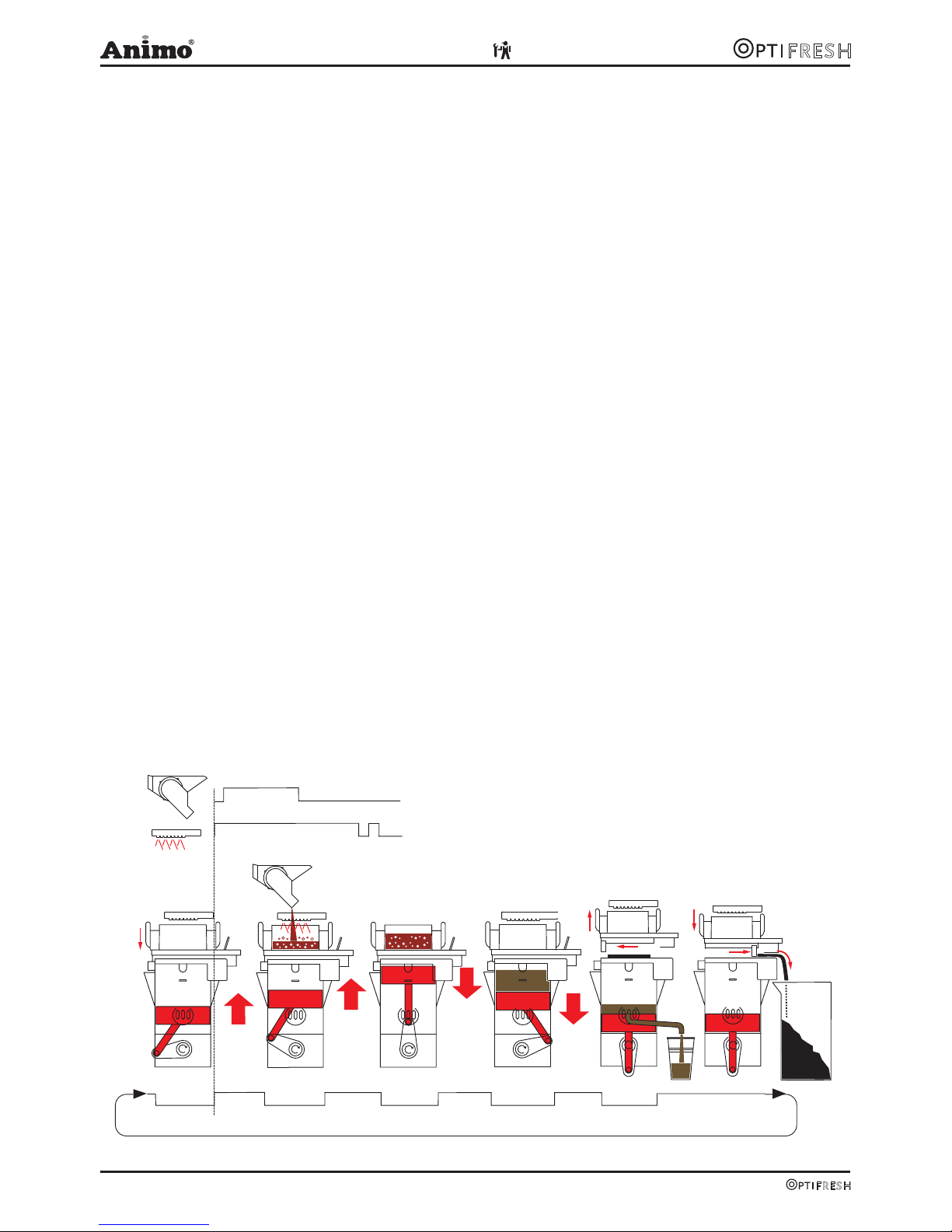
1.7 Brewer unit.......................................................................................................................47
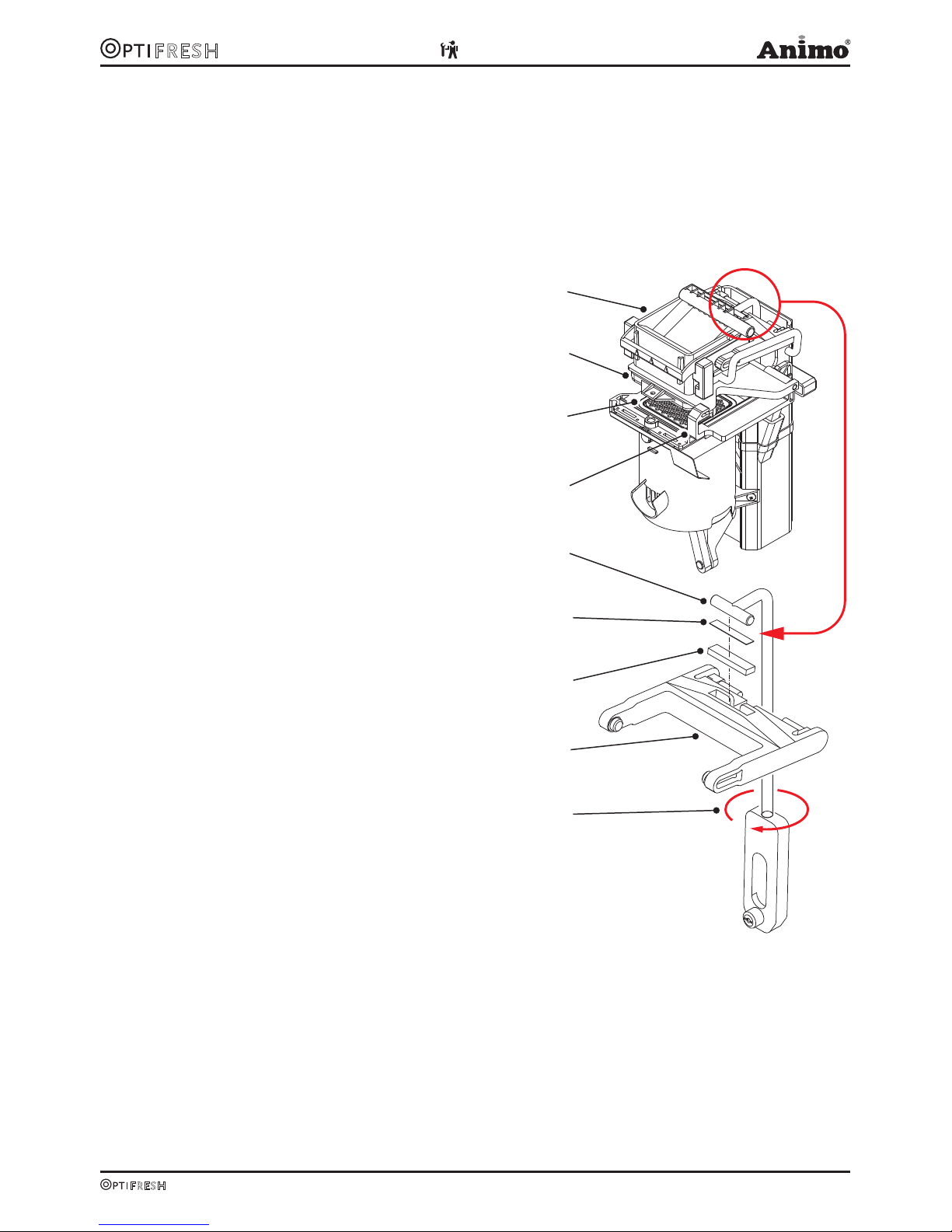
1.7.1 Adjustment.............................................................................................................48
1.7.2 Setting tips.............................................................................................................49
1.7.3 Troubleshooting.....................................................................................................50
2. MENU STRUCTURE .............................................................................................................51
2.1 The operator/service menu..............................................................................................51
2.2 The operator menu ..........................................................................................................52
2.3 The service menu ............................................................................................................53
3. RECIPE SETTINGS...............................................................................................................61
3.1 Quick recipe.....................................................................................................................61
3.2 Model code system ..........................................................................................................61
3.3 Button settings.................................................................................................................62
3.3.1 Standard canister configuration..............................................................................62
3.3.2 Different canister configuration...............................................................................63
3.4 Detailed recipe settings....................................................................................................62
3.5 Timebar recipe settings....................................................................................................62
3.6 Calibrating the hot water valves.......................................................................................64
4. SOFTWARE ..........................................................................................................................65
4.1 Memory card ....................................................................................................................65
4.2 Installing software............................................................................................................65
4.3 Installing a language........................................................................................................65
5. SERVICE ..........................................................................................................................96
5.1 Setting a service parameter.............................................................................................66
5.2 Preventative maintenance ...............................................................................................66
5.2.1 Service contracts...................................................................................................66
5.2.2 Servicing................................................................................................................67
5.3 Descaling instructions......................................................................................................68

05/2008 Rev. 0.6 43
6. COMPONENT ACCESSIBILITY ............................................................................................70
6.1 Electronics summary .......................................................................................................71
6.1.1 Control unit ............................................................................................................71
6.1.2 Interface / Display..................................................................................................72
6.1.3 Power supply.........................................................................................................72
6.2 Main circuit board entrances............................................................................................73
6.3 Main circuit board exits....................................................................................................74
6.4 Main circuit board communication ...................................................................................75
7. TROUBLESHOOTING...........................................................................................................75
7.1 Read log ..........................................................................................................................75
7.2 Clear log ..........................................................................................................................75
7.3 Troubleshooting ...............................................................................................................76
8. COIN MECHANISM (OPTIONAL)..........................................................................................78
8.1 Standard configuration.....................................................................................................78
8.2 Rejecting coins ................................................................................................................78
8.3 Activating existing tokens ................................................................................................79
8.4 Programming a new token...............................................................................................79
8.5 Accepting Euros and Tokens ...........................................................................................79
8.6 accepting Tokens only .....................................................................................................80
8.7 Cleaning the coin holder..................................................................................................80

44 05/2008 Rev. 0.6
© 2008 Animo®
All rights reserved.
No part of this document may be reproduced and/or made public in print, microfilm, electronic media
or any other form without the manufacturer’s prior consent. This also applies to the corresponding
diagrams and/or charts.
PREFACE
Purpose of this document
This document provides directions for use and serves as a service document for trained, authorised
service staff to safety install, programme and maintain this device.
- Trained, authorised service staff are considered to be those who install, programme and maintain
the device, and are able to carry out repairs.
The majority of settings, including product settings, are protected by a PIN code. This PIN code
ensures that users do not gain access to the service menu. It is recommended not to leave this
document with the user after installation and to change the standard factory PIN code.
All sections and paragraphs are numbered. The various figures referred to in the text can be found in
the figures section at the beginning of the manual or with the corresponding subjects.
Pictograms and symbols.
CAUTION
General indication for: IMPORTANT, CAUTION or REMARK.
WARNING
Warning for possible damage to the device, surroundings or environment.
DANGER
Danger of possible severe damage to the device or physical injury.
DANGER
Danger of electricity and voltage.
DANGER
Danger of electrostatic discharge (ESD) in electronics.

05/2008 Rev. 0.6 45
1. BASIC FUNCTIONING
1. Waste bin 6. Fresh brew coffee canister
2. Hot water outlet 7. Coffee canister motor
3. Coffee outlet/Drink outlet (instant) 8. Dispensing valves
4. Brewer 9. Water reservoir
5. Brewer motor 10. Inlet valve
Instant (OptiFresh 2 model and upwards)
11. Instant ingredient canisters 15. Mixer motor
12. Canister motor 16. Mixer impellor
13. Ventilator 17. Mixer housing
14. Evaporation extractor filter cassette 18. Evaporation extractor ring
Cold water (optional)
19. Cold water outlet 22. Inlet valve
21. Cooling unit (base cabinet)
Fresh brew Instant
11
1
2
3
4
5
6
78
12
13
14
15
17
18 16
910 Cold water
(optional)
20
21
19
Fig. 1

46 05/2008 Rev. 0.6
1.1 Boiler System
Turn on the device using the ON/OFF switch. The display will light up.
The magnetic valve (fig. 1-10) will open and the hot water reservoir (fig. 1-9) will be filled to the
maximum electrode. The heating element will be switched on. The display shows [ boiler filling ] and
[ boiler heating ]. As soon as the NTC sensor measures the set temperature, the heating element will
be switched off.
When a drink is being dispensed the water level drops and the maximum electrode is released;
the inlet valve (2.5 litres/min.) opens and immediately refills the reservoir until the maximum level
is reached again. If the water level falls under the minimum electrode level during operation, the
operating panel display will show [refilling boiler]. If the supply of water is not restored within 90
seconds, the display will show the error message [E3 level error] and shut off the inlet valve.
1.2 Temperature regulation
The heating element is turned on when the water temperature falls below the temperature setting and
the minimum electrode registers water. The temperature in the water reservoir is measured using an
NTC precision sensor mounted on the outside wall of the reservoir.
The water temperature also drops when drinks are dispensed. To avoid the temperature regulator from
responding too late, the heating element is switched on as soon as the inlet valve (fig. 1-10) opens
and cold water is added. The heating element switches off again as soon as the inlet valve shuts
off. The software can also be used to delay when the heating element switches off. See menu item
2.4 Settings / Temperature in the service menu. The heating element always switches off when the
maximum boiler temperature of 97˚C is reached.
1.3 Hot water dispensing
When dispensing drinks one of the dispensing valve (fig. 1-8) opens and hot water flows to the brewer
or mixer system. The flow velocity for each valve is set using the adjustment screw on the valve. The
amount of outflow is determined by the length of time that the valve stays open. In order to rinse the
brewer unit and mixer system, a small amount of rinsing water is released shortly after dispensing to
rinse away any ingredient residue.
1.4 Cold water dispensing (optional)
OptiFresh has a built-in cold water option + special base cabinet with built-in cooling unit. When
dispensing a cold-water recipe, inlet valve DV6 opens (fig. 1-21) and allows water to flow from the
mains to the cooling unit cooling coil (fig.1-20). The cooled water already present flows directly to
the cold water outlet (fig. 1-19). As soon as the valve shuts off again the cold water dispenser stops
immediately.
1.5 Ingredients and mixer system
The ingredients canisters (fig. 1-11) are powered by a 130RPM motor (fig. 1-12). The instant product
(ingredient) is forced out of the canister by a coil and drops through the dispensing bent pipes into the
mixer unit (fig. 1-17). At the same time, the dispensing valves (fig. 1-18) dispense hot water into the
mixer unit. The mixer motor (fig. 1-15) blends the instant product with water at a speed of 10,700 RPM
using the mixer rotor (fig. 1-16). The drink flows into the cup via the drink outlet (fig. 1-3). All individual
parts mentioned in this section can be sequentially coordinated using adjustable
parameters (timers) in the control unit.

05/2008 Rev. 0.6 47
1.6 Evaporation extractor system
Evaporation released during mixing is largely absorbed by the evaporation extractor ring (fig. 1-18)
and sucked into the machine via the filter cassette (fig. 1-14). The evaporation and ingredient residue
are absorbed by the filter. The filter (fig. 1-14) can be easily reached (for cleaning purposes) by
dismantling the mixer unit (fig. 1-17). To a large extent, this prevents evaporation from entering the
canister outlet and making ingredients damp.
1.7 Brewer unit
Ground coffee and hot water are dispensed to the permanent filter and are drawn into the filter by
vacuum. After making a fresh brew drink selection the following process (fig. 2) starts:
Start
position
Brewer in resting position. Start
brewer 3
The piston moves down and sucks
the coffee extract through the
permanent filter.
Start
brewer 1
The piston leaves the resting posi-
tion. Ground coffee and hot water is
dispensed to the brewer unit.
Pause 3 Just before the coffee extract
leaves the brewer the piston either
pauses or stops again to make
sure the coffee residue is suf-
ficiently dry.
Pause 1 The piston stops just above the
outlet. Coffee and hot water is still
dispensed.
Start
brewer 4
The piston moves down further so
that the outlet opening opens.
Start
brewer 2
The piston rises and forces air
upwards out of the cylinder, ensur-
ing that coffee and water are mixed
thoroughly. Water dispensing stops
during this cycle.
Pause 4 The coffee is now dispensed to the
cup, goblet or jug.
Pause 2 Piston stops at the highest setting to
enable the coffee to be extracted.
Return to
start
The piston returns to the start
position again. At the same time
the coffee residue is wiped away
by the filter wiper, before it drops
into the waste bin.
Pauze 1 Pauze 2 Pauze 3 Pauze 4
retrun to start
start
position Start 1 Start 2 Start 3 Start 4
1 sec.
6 sec.
3,5 sec.
2,5 sec.
3,8 sec.
4 sec.
3 sec.
2 sec.
1,3 sec.
6,2 sec.
Fig. 2

48 05/2008 Rev. 0.6
1.7.1 Adjustment
If a leak occurs between the brewer unit and the
permanent filter the tensile force of the brewer needs to
be increased.
The tensile force of the brewer should be set so that no
water is able to leak between the brewer unit (fig. 3-1)
and the permanent filter (fig. 3-3).
The tensile force also ensures that the wiper (fig.
3-4) completely pushes the coffee residue off of the
permanent filter.
See figure 3 for the most important brewer parts:
1. Brewer unit
2. Rubber seal (Art. No. 03375)
3. Permanent filter (Art. No. 03374)
4. Wiper (Art. No. 03380)
5. Tension member
6. Adjustment shim* (Art. No. 03384)
7. Rubber
8. H-frame
9. Tension member adjustment
1. First remove the brewer from the device (see section
8.7.2 for instructions).
2. The tensile force can be set by adding adjustment
shims (fig. 3-6) between the tension member (fig.
3-5) and the H-frame (fig. 3-8).
3. Press the H-frame downwards and take the tension
member out of the recess. Place an adjustment
shim* in the recess and replace the tension member.
CAUTION: adding multiple shims at the same time
can cause excess tensile force and damage the
brewer!
4. In most cases this procedure is sufficient for
repairing leaks. If the brewer unit still leaks fit
another adjustment shim.
5. If the brewer unit still leaks remove the two
adjustment shims and then turn in the tension
member once (clockwise). CAUTION: turning in the
tension member should only be done as a last
resort.
6. If the tensile force is correct but the brewer still leaks
do not increase the tensile force any more! For
further help see chapter 1.7.3 Troubleshooting.
1
2
3
4
6
8
7
9
5
Fig. 3
* a extra shim is located behind
the stainless steel panel on the
inside of the door.

05/2008 Rev. 0.6 49
1.7.2 Setting tips
Tensile force too low (fig. 4) Tensile force correct (fig. 5) Tensile force too high (fig. 6)
If the wiper moves over the
upper side of the cylinder it
makes no
contact with the permanent
filter, so that coffee residue is
left on the filter. The wiper does
not bend at all.
If the brewer unit is adjusted in
this way it can leak. If leakage
is severe
this can even result in a
vacuum loss, which means
that the coffee residue remains
too wet (particularly for larger
dispensing volumes).
If the brewer is adjusted
correctly, the wiper moves
carefully over the upper side
of the cylinder and pushes
the coffee residue off of the
permanent filter. The wiper
bends slightly.
When the wiper moves to
the right the coffee residue is
transported to the waste bin.
The coffee residue drops from
the right side of the brewer
straight into the waste bin.
If the brewer is adjusted too
high, the wiper will stretch
and become clearly warped.
Glancing along the long side of
the wiper will show a warped
effect in the rubber.
The brewer is under extreme
pressure and the sound of the
brewer motor audibly changes
as a sign of the severe load.
This may even damage the
wiper!
During the complete brewer
cycle, ball bearings from the
wiper arms and the tension
member are under severe
pressure, resulting in bending.
The ball bearings may then
break away, cracking the plastic
brewer housing.
Signs that the tensile force is too high (fig. 6):
The wiper is severely bent when it slides across the upper side of the brewer cylinder and•
permanent filter.
It appears as if the wiper arm is flattened between the brewer unit and the upper side of the•
brewer cylinder.
The brewer motor sounds as though it is running under extreme pressure.•
The wiper pushes against the coffee residue when moving to the left.•
Accumulation of coffee residue round the waste bin.•
Fig. 4 Fig. 5 Fig. 6

50 05/2008 Rev. 0.6
1.7.3 Troubleshooting
Problem Probable cause Action
The wiper pushes against the
coffee residue when moving to
the left.
The brewer unit does not rise
far enough.
The brewer unit is hindered
during the upward movement.
Check if the brewer unit is able
to move upwards freely.
The brewer unit tensile force is
too high.
Remove one adjustment shim
to reduce the tensile force.
The coffee residue remains
too wet.
Never increase the tensile force
under if the brewer unit tensile
force is set correctly.
There is inadequate suction in
the coffee residue.
Increase the pause 3 time (see
section 1.6)
The water temperature is too
high.
Lower the water temperature.
The permanent filter is dirty or
worn.
Clean or replace the permanent
filter.
If the above-mentioned problem
is not resolved:
Check the brewer unit and
cylinders for fractures.
Replace the defective parts.
Check the cylinder for wear
and tear or scratches.
Replace the defective parts.
Check the Teflon coating for
wear and tear.
Replace the defective parts.

05/2008 Rev. 0.6 51
2. MENU STRUCTURE
2.1 The operator/service menu
The majority of settings, including product settings, are protected by a PIN code. This PIN code
ensures that users do not gain access to the service menu.
It is recommended not to leave this document with the user after installation and to change the
standard factory PIN code.
This section describes how the various settings can be changed by trained, authorized service staff.
You can read about how to gain access to the service menu below. On access to the service menu
the control panel has the following functions:
Summary:
Operator menu Service menu
1.0 Free dispensing 2.1 Quick recipe
1.1 Clock 2.2 Button settings
1.2 Timer settings 2.3 Recipe settings
1.3 Recipe counters 2.4 Settings
1.4 Quick recipe 2.5 Reset counters
1.5 Permanent filter 2.6 Descale / filter
1.6 Software 2.7 Hardware test
1.7 PIN-code 2.8 Read log
2.9 Clear log
2.10 Load defaults
2.11 SD menu
2.12 Change PIN code
2.13 Additional settings
Escape (return without making any changes)
Previous (menu item / increase value)
Next (menu item / decrease value)
Enter (accept menu option) Fig. 7

52 05/2008 Rev. 0.6
2.2 The operator menu
Operator menu
Main item Sub item Item Range Set Description
1.0 Free dispensing
Yes/no Yes Set the device to free or paid dispensing here.
1.1 Clock Time HH:MM Set the clock to the correct local time here.
Date DD-MM-JJJJ Set the clock to the correct local time here.
1.2 Timer Mon-Fri On 00:00
Off 00:00
Set the time when the device should operate here. If
the timer switches off the device it will automatically
revert to standby mode.
Sat On 00:00
Off 00:00
Sun On 00:00
Off 00:00
1.3 Recipe counters
Recipe 1
Recipe 12
Total Off 00:00 Total counter for recipe 1 (free-paid-jugs)
Free Cups Number of free dispensed drinks (recipe 1)
Paid Cups Number of paid dispensed drinks (recipe 1)
Jug Cups Number of dispensed jugs (recipe 1)
Recipes total Total Cups Total counter for all dispensed recipes
Free Cups Total counter for all free dispensed recipes
Paid Cups Total counter for all paid dispensed recipes
Jug Cups Total counter for all dispensed jugs
Rinse counters Brewer Number of brewer rinses
Mixer(s) Number of mixer rinses
Reset counters Total rest of all counters
1.4 Quick recipe Recipe name 1
Recipe name 12
Cup volume
50-200 ml 120ml Use this for setting the volume and strength of cof-
fee, milk, sugar and cocoa easily per recipe (drink
button).
Only the ingredients applicable to the recipe are
shown.
Coffee (1)
-20 / +20% 0%
Decaf (2)
-20 / +20% 0%
Chocolate (3)
-20 / +20% 0%
Topping (4)
-20 / +20% 0%
Sugar (5)
-20 / +20% 0%
1.5 Permanent filter
Reset teller After the permanent filter of the vending unit
(brewer) has reached the maximum number of
brews the filter must be replaced. After replacing
the permanent filter, reset the ‘replace brewer filter’
indicator.
1.6 Software Software version is readable here.
1.7 PIN-code 2-2-2-2-2 PIN code = press the number 2 key five times.

05/2008 Rev. 0.6 53
2.3 The service menu
Service menu
Main item Sub item Item Range Set Description
2.1 Quick recipe Recipe name 1
Recipe name 12
Cup volume
50-200 ml 120ml Use this for setting the volume and
strength of coffee, milk, sugar and cocoa
easily per recipe (drink key).
Only the ingredients applicable to the
recipe are shown.
Coffee (1)
-20 / +20% 0%
Decaf (2)
-20 / +20% 0%
Chocolate (3)
-20 / +20% 0%
Topping (4)
-20 / +20% 0%
Sugar (5)
-20 / +20% 0%
2.2 Button setting
* From software 2.0
Button 1
Button 12
<Recipe name> Recipe list
See section
3.2
Change any recipe buttons here that
standard factory settings. All settings
that correspond to selected recipes are
automatically loaded.
Recipe active Yes/no Yes Use this to place the product concerned
out of service.
Price 0,05-2,00 0,10 For paid dispensing a price can be set
here for each product button.
Cup volume 50-230ml * 120ml Set the desired cup volume here. All other
parameters (e.g. coffee dosage) can be
adjusted automatically. This parameter is
coupled to the quick recipe cup volume!
Cup volume >200ml advice: deactivate
Quick recipe in the Operator menu; 2.4
Settings / I/O Quick recipe.
Cup volume >200ml change brewer
parameters (from software V02.01):
Pause 2 increase to 4,5 s. (2,5)
Start 3 increase to 4,8 s. (4,0)
Pause 3 increase to 5,5 s. (1,5)
Start 4 decrease to 2,2 s. (3,0)
Pause 4 increase to 4,0 s. (2,0)
Multicup 0-20 0 Set the number of cups that should be
dispensed when the key switch is in the
jug setting.
Key switch 0-1-2-3 0 / 1 Recipe button concerned works as follows:
0= key switch setting n/a
CUP (paid) or JUG* (paid)
1= key switch |: CUP (paid)
key switch –: JUG* (paid)
2= key switch |: no dispensing
key switch –: JUG* (paid)
3= key switch |: CUP (paid)
key switch –: JUG* (free)
(*when multicup is set to >1)
Push & Hold Yes-No No If set to yes: pressing this button starts the
hot/cold water dispensing and releasing it
stops the hot water dispensing.
Only use this option for Water 4 and Water
6 in combination with a hot/cold water
recipe button.
Drip time 0-10 sec. 2 sec. The length of time that the product
continues to run from the brewer or mixer.
After this time has elapsed a new drink
selection can be made.

54 05/2008 Rev. 0.6
Service menu continued ….
Main item Sub item Sub Item Range Description
2.3 Recipe setting Recipe name 1
Recipe name 12
Unit 1 DV 1 WT 0,0-30,0 s Waiting time Water 1
DV 1 0,0-100,0 ml Dispensing amount Water 1 (Brewer)
Rinse 1 WT 0,0-20,0 s Waiting time Rinsing Water 1
Rinse 1 0,0-15,0 ml Dispensing amount Rinsing Water 1 Auto-
matically deducted from Water 1
Ingredient 1 WT 0,0-30,0 s Waiting time Ingredient 1
Ingredient 1 0,0-50,0 s Product dispensing time Ingredient 1
Ingredient 2 WT 0,0-30,0 s Waiting time Ingredient 2
Ingredient 2 0,0-50,0 s Product dispensing time Ingredient 2
Start brewer 0,0-30,0 s 1st start time brewer
Pause 1 brewer 0,0-30,0 s 1st pause time brewer
Start 2 brewer 0,0-30,0 s 2nd start time brewer
Pause 2 brewer 0,0-30,0 s 2nd pause time brewer
Start 3 brewer 0,0-30,0 s 3rd start time brewer
Pause 3 brewer 0,0-30,0 s 3rd pause time brewer
Start 4 brewer 0,0-30,0 s 4th start time brewer
Pause 4 brewer 0,0-30,0 s 4th pause time brewer
Unit 2 DV 2 WT 0,0-30,0 s Waiting time Water 2
DV 2 0,0-100,0 ml Dispensing amount Water 2
Rinse 2 WT 0,0-20,0 s Waiting time Rinsing Water 2
Rinse 2 0,0-15,0 ml Dispensing amount Rinsing Water 2 Auto-
matically deducted from Water 2
Ingredient 3 WT 0,0-30,0 s Waiting time Ingredient 3
Ingredient 3 0,0-50,0 s Product dispensing time Ingredient 3
Ingredient 4 WT 0,0-30,0 s Waiting time Ingredient 4
Ingredient 4 0,0-50,0 s Product dispensing time Ingredient 4
Mixer 2 WT 0,0-30,0 s Waiting time Mixer 2
Mixer 2 0,0-50,0 s Mixing time Mixer 2
Unit 3 DV 3 WT 0,0-30,0 s Waiting time Water 3
DV 3 0-100 ml Dispensing amount Water 3
Rinse 3 WT 0,0-20,0 s Waiting time Rinsing Water 3
Rinse 3 0,0-15,0 ml Dispensing time Rinsing Water 3
Automatically deducted from Water 3
Ingredient 5 WT 0,0-30,0 s Waiting time Ingredient 5
Ingredient 5 0,0-50,0 s Product dispensing time Ingredient 5
Ingredient 6 WT 0,0-30,0 s Waiting time Ingredient 6 (optional)
Ingredient 6 0,0-50,0 s Product dispensing time Ingredient 6
(optional)
Mixer 3 WT 0,0-30,0 s Waiting time Mixer 3
Mixer 3 0,0-50,0 s Mixing time Mixer 3

05/2008 Rev. 0.6 55
Service menu continued ….
Main item Sub item Sub Item Range Description
2.3 Recipe setting
(continued…)
Recipe name 1
Recipe name 12
DV 4 WT 0,0-30,0 s Waiting time Water 4
DV 4 0,0-100,0 ml Dispensing amount Water 4
(Hot water dispensed)
DV 5 WT 0,0-30,0 s Waiting time Water 5
DV 5 0,0-100,0 ml
Dispensing amount from an extra hot water
valve Water 5 (reserved for a Brewer
By-Pass option).
DV 6 WT 0,0-30,0 s Waiting time Water 6
DV 6 0,0-100,0 ml Dispensing amount from an extra inlet
valve Water 6 (Cold Water option)
Strength Coffee 0-50% Use the strength setting item to add an
ingredient to the strength adjustment.
Ingredient strength adjustment:
0= off / > 1 = on
Example: [coffee] 20%
Example: [cocoa] 40%
Strength Decaf 0-50%
Strength Chocolate 0-50%
Strength Topping 0-50%
Strength Sugar 0-50%
Strength Ingrediënt 6
Option
0-50%
Strength
-- - 0 + ++
-20% -10% 0 10% 20%
Strength
-- - 0 + ++
-40% -20% 0 20% 40%

56 05/2008 Rev. 0.6
Service menu continued…
Main item Sub item Item Range Set-
ting Description
2.4 Settings
* From software 2.0
Language English Language choice display.
Ex factory setting English.
Dutch
German
French
Temperature
Temp. boiler 70-97°C *
95°C * Boiler temperature standard model
1A - 5A
90°C * Boiler temperature FreshBrew +
instant model 6A t/m 9A
Hysteresis 0-10°C 2°C Temperature drop, after which boiler
must reheat
Output block 70-95°C 78°C
Boiler temperature disables dispens-
ing. Display: [Out of order, boiler
heating]
Output release 70-95°C 85°C Boiler temperature allows dispens-
ing again
Stand-by 60-95°C 60°C Boiler temperature during stand-by
Extended Heating 0-5 sec 1 sec
To maintain the optimum boiler tem-
perature the heating element and
inlet valve switch on simultaneously.
Set the waste delay of the element
here after the inlet valve is closed.
Inlet valve
Heating
Display Show clock Yes/no No Show clock in display
Show date Yes/no No Show date in display
Message text Yes/no No
Show message text (running text) in
display. Only shown if Display Date,
Clock or both are set to no. Mes-
sage text only programmable using
a future PC programme.
Use bleeper Yes/no Yes Sound signal on or off
Fan time 0-300 sec. 60 s. Duration of Fan speed 1 after
dispensing
Fan speed 1 40-100% 50% Fan speed when resting
Fan speed 2 70-100% 100% Fan speed during dispensing
Inlet valve
Heating

05/2008 Rev. 0.6 57
Service menu continued …..
Main item Sub item Item Range Set-
ting Description
2.4 Settings
(continued…)
* From software 2.0
Coin system G13 Coin channel 1
Coin channel 6
0-100,00 +
Token
€ 0,05
€ 0,10
€ 0,20
€ 0,50
€ 1,00
€ 2,00
Coin value setting for each channel.
€0.05-€2 respectively.
0.00=free
TOKEN=coffee token
Single vend ja-nee ja
Yes: any excess credit is not
retained for next drink. No: credit
retained for next drink.
Max coin accep.
€ 0,05-
100,00 € 1,00
Coins larger than € 1.00 are rejected
and ejected through the return slot
of the coin mechanism. Adjust to the
highest recipe product price.
Point position 0-2 2 Decimal position in amount
Show credit Yes/no Yes Show credit on the display
MDB No MDB software available yet
I/0 Reset counter Yes/no No Add Reset counters menu item to
the operator menu
I/0 Quick recipe Yes/no Yes Add Quick recipe menu item to the
operator menu
* Drip tray sign. Yes/no Yes Turns off drip tray sensor software.
2.5 Reset counters Rinse counters Brewer counter? Reset brewer spoelteller
Mixer counter? Reset mixer spoelteller
Recipe counters Recipe counter 1
Recipe counter 12
Reset recepttellers per recept.
Reset counter total Reset totaal tellers
Reset all counters Reset alle tellers ineens
2.6 Descale/filter Service moment 0-25000 12500 After the Service Due setting has
been reached the Descale/filter
indicator will be displayed. See sec-
tion 5. Service
Service counter ????? The number of beverages dis-
pensed is counted here. Check here
to see how far the machine is from
periodic maintenance (descaling
boiler or replacing water filter).
Reset serv. coun After periodic maintenance has
been carried out (boiler descaled or
filter replaced) the service counter
should be set to nil.

58 05/2008 Rev. 0.6
Service menu continued….
Main item Sub item Sub Range Description
2.7 Hardware test Inputs Temperature Boiler temp
Shows the status of the sensors/switches
indicated
Level sensors High Yes/no
Low Yes/no
Drip tray sensor Yes/no
Waste bin Yes/no
Door switch Yes/no
Brewer switch Yes/no
Key switch Yes/no
Outputs
Test by holding
in recipe button
11.
# During test the
display shows
the Nominal
current (mA)
When the
Nominal current
of a output rises
above the set
current *
mentioned output
will be shut off.
Caution: BM 1
goes through a
complete drinks
cycle.
KW1
* 400 mA
Inlet valve (Boiler)
DV1 Dispenser valve 1 (Brewer)
DV2 Dispenser valve 2 (Mixer 2)
DV3 Dispenser valve 3 (Mixer 3)
DV4 Dispenser valve 4 (Hot water)
DV5 Dispenser valve 5 (n/a)
DV6 Inlet valve 6 (Cold water) optional!
IM1 #
* 400 mA
Ingredients motor 1 (Canister 1)
IM2 # Ingredients motor 2 (Canister 2)
IM3 # Ingredients motor 3 (Canister 3)
IM4 # Ingredients motor 4 (Canister 4)
IM5 # Ingredients motor 5 (Canister 5)
IM6 # Ingredients motor 6 (Canister 6)
BM/MM1 #
* 800 mA
Brewer motor
MM2 # Mixer motor 2
MM3 # Mixer motor 3
Ventilator * 200 mA Ventilator
LED’s LED’s
Calib. valves
Test by holding
in recipe button
11 (for 1 sec.)
to open the rel-
evant valve for
10 seconds.
DV1 15 ml / sec Calibrate to 150 ml (10 sec x 15 ml)
DV2 15 ml / sec Calibrate to 150 ml (10 sec x 15 ml)
DV3 15 ml / sec Calibrate to 150 ml (10 sec x 15 ml)
DV4 20 ml / sec Calibrate to 200 ml (10 sec x 20 ml)
DV5 20ml / sec. Calibrate to 200ml (10sec. x 20ml)
(Optional valve for Brewer By-pass)
DV6 42 ml / sec Inlet valve cannot be calibrated (fixed flow)

05/2008 Rev. 0.6 59
Service menu continued….
Main item Sub item Item Description
2.8 Read log Saves last 20 error messages, including date and time
2.9 Clear log Are you sure? Clears log
2.10 Load defaults
# See chapter 3.2
Model code system
* available from
software version 2.0
Model #
OF1A xx00
OF2A xx00
OF3A xx00
OF4A xx00
OF5A xx00 *
OF6A xx00 *
OF7A xx00 *
OF8A xx00 *
OF9A xx00 *
Are you sure? When a new circuit board is introduced it is necessary to load
defaults. When loading defaults it must be stated on the OptiFresh
model plate. The correct model settings are not loaded until the
question ‘Are you sure?’ has been confirmed.
Attention:
● Before you start changing the button- and/or receipt- settings, first
close the service menu, only after re-entering the service menu the
new model settings will be activated.
● When you confirm this setting all loaded factory settings and
changed programmed values will be lost.
● After loading defaults the PIN code reverts to 2-2-2-2-2 and the
language reverts to English. Change if necessary.
2.11 SD menu
Before saving
or loading data,
insert an empty SD
memory card into
the card reader .
This is located
behind the stainless
steel panel on the
inside of the door.
SD card
specifications:
- 16MB or greater
- FAT16 format
Load data Pers. settings This menu item is for loading personal settings to the device using
an SD memory card. This file contains the (amended) personal set-
tings for menus: 2.4 Settings / 2/6 Descale-filter / 2.13 Additional
settings. The data file (Ofxxxx00.mdu) should be on the SD card.
Language This menu item is for loading a different language set to the
device. The data file (xxxxxx.tlf) should be on the SD card.
Recipe This menu item is for loading personal recipes to the device using
an SD memory card. This file contains the (amended) personal reci-
pes for menus: 2.1 Quick recipe / 2.2 Button settings / 2.3 Recipe
settings. The data file (OFxxxx00.rcu) should be on the SD card.
Save data Pers. settings This menu item is for saving personal settings to an SD memory
card and copying them to another device.
All settings amended in menus: 2.4 Settings / 2.6 Descale-filter /
2.13 Additional settings are loaded to the SD card in one data file
(OFxxxx00.mdu).
Recipes This menu item is for saving personal recipes to an SD memory
card and copying them to another device.
All settings amended in menus: 2.1 Quick recipe / 2.2 Button
settings/ 2.3 Recipe settings are loaded to the SD card in one data
file (OFxxxx00.rcu).
2.12 Change PIN
New PIN code Repeat PIN code This menu item is for changing the PIN code using buttons 1-4 only.
The entire service menu is accessed with this PIN code, which
prevents unintentional changes from being made to the machine
settings by untrained staff.
• The ex-factory PIN code is 2-2-2-2-2
PIN code forgotten or needs to be deactivated?
The PIN code input display (operator menu item 1.7) shows a
number on the right. Enter the corresponding PIN code (see list on
p.60) to access the service menu.
Memory Card
Memory Card

60 05/2008 Rev. 0.6
Service menu continued…
Main item Sub item Item Range Set Description
2.13 Addit. settings
From software 2.0
moved to menu
2.4.10
Waste manag.
Cup amount 0-1000 250
After reaching the set total of brewer
movements, dispensing is disabled and
the display reads: Out of order – Waste
bin full
Almost full sign. 0-1000 230
After reaching the set total of brewer move-
ments, the display reads: Waste bin almost
full
Time-out reset 0-50 sec. 15 s The length of time that the waste bin is al-
lowed to be removed (for emptying). When
replacing it the (internal) waste bin counter is
reset. Any display messages disappear.
Waste bin sign.. Yes/no Yes Turns off waste bin sensor software (bypass).
Drip tray sign. Yes/no Yes Turns off drip tray sensor software.
Cycle counter xxxxx 0-99999 This Cycle counter records the number of
vends the brewer has made. Tip: This counter
can be reset after maintenance if the brewer
has been checked.
Reset c. counter Reset counter? Reset Cycle counter (Brewer)
Perm.filter coun xxxxx 0-10.000 6000 When the set number of (Brewer) vends is
reached the display reads ‘Replace perma-
nent filter’ when switching on.
Reset p. filter Reset counter? Reset the permanent filter counter after
(preventative) replacement
PIN Code Table No. Pincode No. Pincode
1 34242 11 13332
2 31434 12 12413
3 41343 13 43121
4 43232 14 11142
5 23341 15 21211
6 42131 16 12233
7 24244 17 34144
8 23241 18 41433
9 24323 19 31241
Table 1 10 31332 20 22324
Water Hardness Table Water
Quality
Hardness Limescale
Indicator ...cups
°D °F mmol/l mgCaCo3/l
Very hard 18-30 32-55 3,2-5,3 321- 536 5000
Hard 12-18 22-32 2,2-3,2 214-321 8500
Average 8-12 15-22 1,4-2,2 268-214 12.500*
Soft 4-8 7-15 0,7-1,4 72-268 20.500
Table 2 Very soft 0-4 0-7 0- 0,7 0-72 0 = off
Table of contents
Other Animo Coffee Maker manuals

Animo
Animo OptiFresh Bean Product guide

Animo
Animo CB 20W User manual

Animo
Animo M100W User manual

Animo
Animo TV B200 W User manual

Animo
Animo OptiBean Product guide

Animo
Animo PROFESSIONAL 25P User manual

Animo
Animo TA 100 User manual

Animo
Animo OptiFresh Bean User manual

Animo
Animo TA 202 W User manual

Animo
Animo OptiVend Choco User manual

Animo
Animo M200W User manual

Animo
Animo OptiBean Touch Product guide

Animo
Animo OptiBean Touch User manual

Animo
Animo OptiVend HS DUO NG User manual

Animo
Animo ComBi-line Series User manual

Animo
Animo DE 5 User manual

Animo
Animo A140 User manual

Animo
Animo Excelso User manual

Animo
Animo Aromatic A 100 User manual

Animo
Animo OptiVend Choco User manual