Anritsu HR-1100 User manual

Handheld Thermometer
Instruction Manual
HR-1100/HR-1200/HR-1300
AE-100288
Second edition (Jun 2022)
Anritsu Meter Co., Ltd.
2-4-5, Shimomeguro, Meguro-ku, Tokyo, 153-0064, Japan
TEL: +81-3-3491-9181
FAX: +81-3-3493-6729

To safely operate and service the thermometer and to prevent any product
damage and/or maintain the precise temperature measurement results, please
carefully follow the instructions below:
Do not use this product for any purpose other than taking temperature
measurements.
If any abnormalities are found, immediately stop using the product.
Do not disassemble or modify the product.
Do not use any power supply other than commercially available dry batteries
and/or a dedicated adaptor.
Insert the batteries in the correct manner (pole+ to pole+).
Remove the batteries when depleted or when the product is not expected to be
used for an extended period of time.
Do not mix old and new batteries or batteries of different makes or types.
● Do not throw into an open fire. Do not short circuit, disassemble, or heat.
● Do not recharge the batteries at any time.
● Use specified type batteries.
● To prevent electric shock, do not touch the metal parts or terminals of the probe cable
or analog output cable during measurement.
● To prevent electric shock, if the probe is still in contact with the voltage application part
even when the power is turned off, disconnect the probe before setting the analog
output cable or device.
※ When measuring under the influence of high voltage and high frequency, there is a risk
of electric shock and measurement failure, so please contact us.
Safety information
Caution
Warning

Introduction
Thank you very much for purchasing this Anritsu Meter product.
This instruction manual has been carefully prepared to ensure that the product can be
used safely and securely.
Please carefully and thoroughly read this instruction manual, fully understand all the
individual functions, and use the product properly.
Should you have any unclear issues or questions while operating the product, please
refer to this instruction manual.
Notes
The contents of this document and/or product specifications are subject to change
without prior notice.
Unauthorized reproduction of any part of this document is strictly prohibited.
This instruction manual has been prepared with absolute care. Please free feel to
contact our company or your retailer should you discover any omissions or
mistakes.
In no event is Anritsu Meter liable to anyone for any indirect, special, or
consequential damages as a result of using this product.
Warranty and After-sales Service
Warranty
This product has been submitted to strict tests and inspections prior to delivery. Anritsu
Meter warrants this product to be free from defects in material and workmanship for a
period of one (1) year from date of delivery. Should any failures arise due to defects
during manufacture or accidents during transportation, please contact our company or
your retailer. For any failures during the warranty period which are deemed our
responsibility, we will exchange the necessary parts or carry out repairs at no cost.
However, the warranty will be considered to be voided (i.e., the customer pays for
repairs) in the following cases:
- Failure due to a fire, earthquake, or any other force majeure.

- Failure due to misuse, abuse, and/or modification. (Please note that if the case of the
product is opened or the screws are loosened, such an act will be regarded as a
modification.)
Note: Our thermocouple probes are consumables and are not covered by the warranty.
After-sales Service
- If you think the product is not correctly working, please refer to this instruction manual.
Should any issue persist, please contact our company or your retailer.
- Repairs during the warranty period are subject to the content of the warranty sheet.
However, only when used in Japan. Repairs after the warranty period has elapsed will
be carried out only if such repairs recover and maintain the product functions.
- If there is a need to return the product for repair or calibration, please pack it in the
original packaging that was used for delivery. If such packaging is not available, please
enclose the product with sufficient cushioning material and return the product in a
condition where no damage can be caused.

Table of Contents
1. General .............................................................................................. 1
2. Unpacking .......................................................................................... 1
2.1. Unpacking ................................................................................................... 1
2.2. Repacking ................................................................................................... 1
3. Name and Explanation of Each Part ................................................. 2
3.1. External View ............................................................................................. 2
3.2. LCD Display ............................................................................................... 3
4. Preparations Before Taking Measurements ...................................... 4
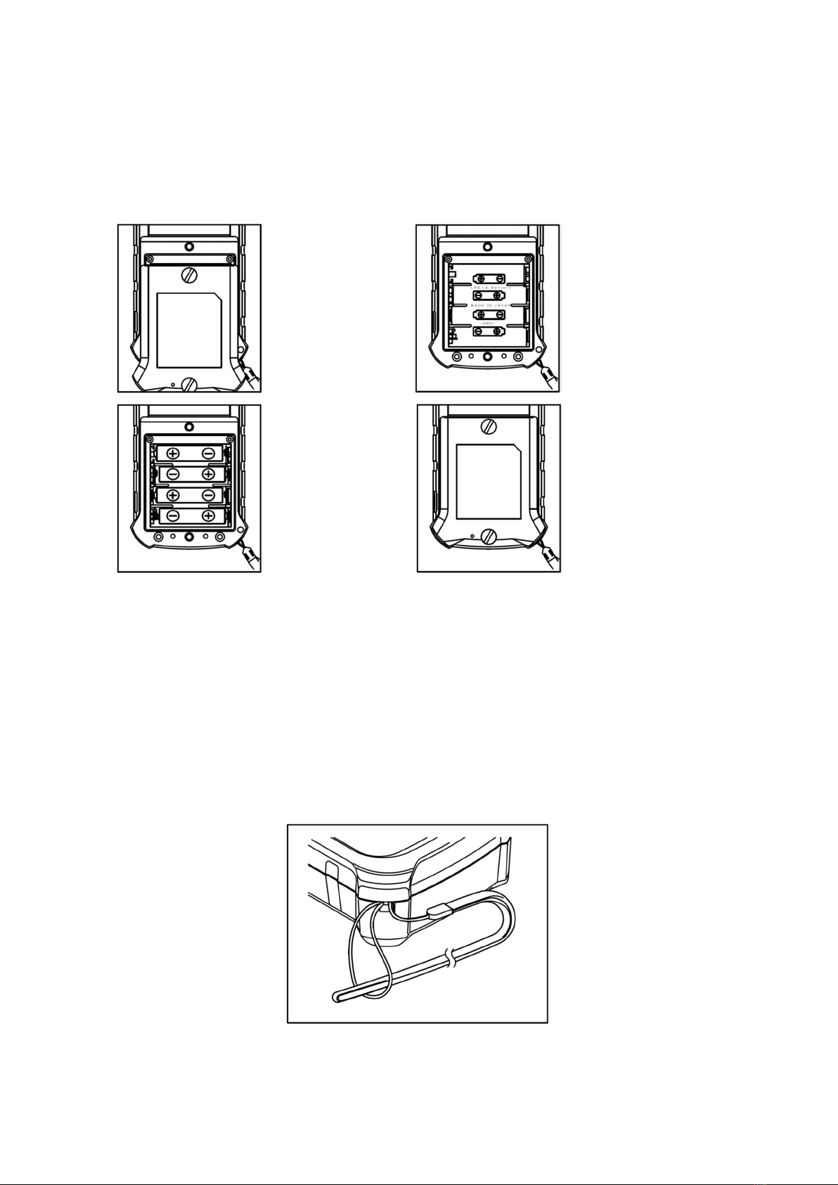
4.1. How to Install the Batteries ....................................................................... 4
4.2. How to Use the Hand Strap ....................................................................... 4
4.3. How to Use the AC Power Supply [Applicable Models: HR-13** Series] . 5
4.4. How to Set the Probe .................................................................................. 6
4.5. How to Use the Soft Case ........................................................................... 6
5. Operations and Functions ................................................................. 7
5.1. Power ON/OFF ........................................................................................... 8
5.2. HOLD Function .......................................................................................... 8
5.3. Automatic Power OFF Function ................................................................ 9
5.4. Resolution Change [Applicable Models: HR-12*0/HR-13*0] ..................... 9
5.5. P/V Hold Function [Applicable Models: HR-12*0/HR-13*0] ................... 10
5.6. Turning the Backlight ON/OFF [Applicable Models: HR-12*0/HR-13*0]
10
5.7. Calibration Function [Applicable Model: HR-13*0] ................................ 11
5.8. Alarm Function [Applicable Model: HR-13*0] ......................................... 12
6. Analog Output [Applicable Model: HR-13*1] ................................... 15
6.1. Turning the Analog Output ON/OFF....................................................... 16
7. Retention of Setup Data .................................................................. 17
8. Checking the Remaining Battery .................................................... 17
9. Error Messages ................................................................................ 18
9.1. Indication of a Broken Element of the Probe ........................................... 18
9.2. Overrange Indication ............................................................................... 18
9.3. Battery Voltage Drop Indication .............................................................. 18
10. Maintenance .................................................................................... 19
10.1. Storage ...................................................................................................... 19
10.2. When the Case of the Instrument Gets Dirty .......................................... 19
11. Troubleshooting: Before Contacting Support .................................. 20

12. HR Series Specifications .................................................................. 21

1
1. General
This product is a handheld thermometer for high precision, reliability, and
usability. It has a high-precision analog technology and a microcomputer to
digitally correct measured data, making highly stable and high-precision
temperature measuring possible.
2. Unpacking
2.1. Unpacking
Please check if the following items are present when unpacking. We make sure
all items are carefully packed, but should you find any missing or failed items,
please contact our company or your retailer.
Item Q’ty
Applicable
model
Main unit 1 All models
Soft case 1 All models
Hand strap 1 All models
Analog output cable 1 HR-13*1
Alarm output cable 1 HR-13**
Alkaline AA battery 4 All models
Instruction manual 1 All models
Test report 1 All models
Warranty sheet 1 All models
User registration sheet 1 All models
2.2. Repacking
To move this instrument (such as transportation by car), pack it in its original
packaging. If such packaging is not available, fully protect the instrument with
shock-absorbing material (Styrofoam, etc.). Please note that if packing
materials generate dust or moisture, the instrument may become damaged.
Please use dry packing materials that do not generate dust.

2
3. Name and Explanation of Each Part
3.1. External View
(HR-1301)
① Probe input connector
② Alarm output connector/Analog output connector
③ LCD display
④ Key switch panel
⑤ Battery housing
⑥ AC adaptor jack
⑦ Hand strap

3
3.2. LCD Display
Description
HR-11*0 HR-12*0 HR-13*0 HR-13*1
① ALM_BZ
segment ● ●
② ↑↓ segment ● ●
③ A-OFF segment ● ● ● ●
④ Analog output
segment ●
⑤ HOLD segment ● ● ● ●
⑥ ALM segment ● ●
⑦ Main display ● ● ● ●
⑧ P segment ● ● ●
⑨ Battery segment ● ● ● ●
⑩ CAL segment ● ●
⑪ °C segment ● ● ● ●
⑫ Lo segment ● ●
⑬ Hi segment ● ●
⑭ Sub display 1 ● ● ●
⑮ V segment ● ● ●
⑯ Sub display 2 ● ● ●
④
⑫
⑬
③
⑤
⑦
⑧
⑨
⑭ ⑮ ⑯
⑪
⑩
⑥
① ②

4
4. Preparations Before Taking Measurements
4.1. How to Install the Batteries
Make sure to turn the power off when replacing batteries.
Note: To maintain the waterproofing performance, firmly tighten the screws on
the battery cover.
Applicable models: HR-11*0/HR-12*0
4.2. How to Use the Hand Strap
Place the enclosed hand strap on your wrist to prevent the instrument from
dropping.
Loop the thin cord of the strap through the hole and then pull the other end of
the hand strap through that loop.
(1) Loosen both
screws and
open the cover
of the battery
housing.
(2) Pay attention
to the
orientation of
the batteries.
(3) Install the
batteries.
(4) Reattach the battery
housing cover, tighten
both screws, and then
press the edge of the
cover to secure it.

5
4.3. How to Use the AC Power Supply [Applicable Models: HR-
13** Series]
(1) Turn off the power of the instrument and then connect the connection plug
of the AC adaptor to the main unit as follows:
(2) Connect the power plug of the AC adaptor to an AC mains (100 VAC).
Note: The AC adaptor is available as an option. Please use one as
specified by Anritsu Meter.

6
4.4. How to Set the Probe
Set the probe to the main unit as shown in the illustration below. It is designed
so that if the probe orientation is incorrect, it cannot be fully inserted. If the
probe is forcefully inserted, failure may result. Please check the probe’s
orientation before inserting it.
[HR-1*00] [HR-1*50]
4.5. How to Use the Soft Case
To protect the instrument from dirt or scratches, etc., use the attached soft
case.
When using an AC adaptor, alarm output, and/or analog output, open a hole at
the relevant position on the soft case by using scissors or a similar object.

7
5. Operations and Functions
This instruction manual covers the HR-1100 Series, the HR-1200 Series, and
the HR-1300 Series. Depending on the model purchased, some functions may
not be available. Please refer to the table below.
Table of functions supported by individual series
Function
HR-11*0 HR-12*0 HR-13*0 HR-13*1
Power ON/OFF ● ● ● ●
Hold ● ● ● ●
Automatic power
OFF ● ● ● ●
Resolution change ● ● ●
P/V hold ● ● ●
Backlight ● ● ●
Calibration ● ●
Alarm ● ●
Analog output ●
Waterproofing
function (equivalent
to IPX5)
● ●
Note: About analog output
- 1 mV/°C and 10 mV/°C can be switched using the resolution change.
- The factory setting is “enabled” (outputting). As this setting increases battery
consumption, it is recommended to turn the analog output off when not in use.

8
5.1. Power ON/OFF
Pressing the POWER key will illuminate all the indicators for about three
seconds and start the measurements.
Press the POWER key again to turn the instrument off.
All illuminated (HR-1300) Normal measurement
5.2. HOLD Function
Press the HOLD key to maintain the indicated values during measurements.
HOLD will illuminate on the screen while HOLD is on. To release the HOLD
function, press the HOLD key again.
HOLD illuminated

9
5.3. Automatic Power OFF Function
When the AUTO OFF key is pressed, “AUTO OFF” symbol will illuminate on the
screen. If no key operation is performed for a certain period of time (about five
minutes), the power will automatically be turned off, preventing the unit from
remaining turned on. To release the Automatic Power OFF function, press the
AUTO OFF key again.
5.4. Resolution Change [Applicable Models: HR-12*0/HR-13*0]
Press the RESO key to switch the resolution.
0.1°C resolution indication: A range between -104.9
and 504.9°C is displayed with a 0.1°C resolution. If a
temperature is out of this range, the instrument will
automatically indicate it at a 1°C resolution.
1°C resolution indication: The 1°C resolution is
applied to all temperatures.
0.1°C resolution indication 1°C resolution indication
“AUTO OFF” symbol illuminates
RESO

10
5.5. P/V Hold Function [Applicable Models: HR-12*0/HR-13*0]
Press the P/V-HOLD key to enter the P/V Hold function.
The lowest and highest values will be displayed in the
sub-screens. Press the P/V-HOLD again to return to
normal measurements.
Normal measurement P/V mode
5.6. Turning the Backlight ON/OFF [Applicable Models: HR-
12*0/HR-13*0]
Press the ☀ key to turn on the backlight so that
indications on the screen can be seen in dark places.
Press the ☀ key again to turn off the backlight.
Note: When the backlight is ON, more battery usage will
be incurred. Don’t forget to turn it off.
Max.
value
Min.
value
Current
temperature
P/V-HOLD

11
5.7. Calibration Function [Applicable Model: HR-13*0]
The calibration function offsets-compensates the measured data.
(1) Calibration settings
(i) Make the probe contact the object of measurement, and when the
indication becomes stable, press the CAL SET key.
Note: When the CAL SET key is pressed, the calibrated temperature
first shown is a value that is calculated by adding the offset value that
was set last time to the current temperature.
In the above case, the last offset value is +0.4°C.
(ii) Use the ˄ and ˅ keys to set up a calibration value (sub-screens) to a
desired temperature.
Note: The setting range with the ˄ and ˅ keys are limited within
±10°C of measured values.
(iii) Press the ENTER key to complete the setting and automatically
return to the calibration mode.
Pressing the CAL SET key before pressing the ENTER key will
interrupt the setup process and the normal mode will resume.
(2) Calibration mode
During calibration mode, “CAL” is displayed on the
screen. In the main display, a value calculated by
adding the offset value to the current temperature is
displayed.
In the case of the image on the left, the current
temperature is 199.6°C, and the offset value is +0.4°C.

12
(3) Releasing the calibration mode
To release the calibration mode, press the CAL SET key
twice.
5.8. Alarm Function [Applicable Model: HR-13*0]
The alarm function indicates data abnormalities when
measured data go out of the setup range (upper and
lower limits.) For every measurement, the alarm
function is turned on. When an abnormality is
detected, a mark to indicate the abnormality is shown
at the top of the screen.
Measured data status Mark indicating abnormality
Upper limit ≤ Measured data ALM ↑
Lower limit ≥
Measured data ALM ↓
Within upper/lower limits of
alarm None
(1) Setting of upper/lower limits of alarm
(i) When the ALM SET key is pressed, the setting
screens are switched in order as follows. Display the
desired screen to make changes.

13
Normal measurement Upper limit setting Lower limit setting
(ii) Change the numerical value with the ˄ and ˅
keys. Press and hold the ˄ and ˅ keys to increase the
rate of change by 10 and 100 times.
(iii) Press the ENTER key to make new settings
effective. If the ALM SET key is pressed before
pressing the ENTER key, new setups are canceled.
(2) Turning buzzer sound ON/OFF
When the key is pressed, “ALM” and will illuminate on the
screen. When abnormal data is detected, the buzzer sound is outputted.
Press the key again to turn the buzzer sound output off.
SET
SET
SET
Upper
limit
Lower
limit
“ALM”
illuminates ↑ or ↓

14
(3) External outputs
(i) Signal name and pin assignments
Pin # Signal
1 ALM1 (upper limit)
2 ALM1 (upper limit)
3 ALM2 (lower limit)
4 ALM2 (lower limit)
Note: Dedicated cable: ALMHA-1.5
(ii) Output signals
It compares the current temperature with the alarm set value and outputs
the contacts as shown in the table below.
Measurement data status Upper limit alarm
Lower limit alarm
Higher than upper limit Close Open
Within upper and lower limits Open Open
Lower than lower limit Open Close
Note: The alarm output uses a photo MOS relay.
ON resistance (internal protection resistance 400Ω, photo MOS relay
ON resistance 50Ω)
Drive voltage MAX.25V
(iii) Example of connection
Note: Make sure to turn the power off before connecting/disconnecting the
instrument to other equipment.
This manual suits for next models
2
Table of contents
Other Anritsu Thermometer manuals