Anritsu HR-1400 User manual

Handheld Thermometer
Instruction Manual
HR-1400
AE-100289
First edition (May 2022)
Anritsu Meter Co., Ltd.
2-4-5, Shimomeguro, Meguro-ku, Tokyo, 153-0064, Japan
TEL: +81-3-3491-9181
FAX: +81-3-3493-6729


To safely operate and service the thermometer and to prevent any product
damage and/or maintain the precise temperature measurement results, please
carefully follow the instructions below:
Do not use this product for any purpose other than taking temperature
measurements.
If any abnormalities are found, immediately stop using the product.
Do not disassemble or modify the product.
Do not use any power supply other than commercially available dry batteries
and/or a dedicated adaptor.
Insert the batteries in the correct manner (pole+ to pole+).
Remove the batteries when depleted or when the product is not expected to be
used for an extended period of time.
Do not mix old and new batteries or batteries of different makes or types.
● Do not throw into an open fire. Do not short circuit, disassemble, or heat .
● Do not recharge the batteries at any time.
● Use specified type batteries.
● To prevent electric shock, do not touch the metal parts or terminals of the sensor cable
or analog output cable during measurement.
● To prevent electric shock, if the sensor is still in contact with the voltage application
part even when the power is turned off, disconnect the sensor before setting the
analog output cable or device.
※ When measuring under the influence of high voltage and high frequency, there is a risk
of electric shock and measurement failure, so please contact us.
Safety information
Caution
Warning

Introduction
Thank you very much for purchasing this Anritsu Meter product.
This instruction manual has been carefully prepared to ensure that the product can be
used safely and securely.
Please carefully and thoroughly read this instruction manual, fully understand all the
individual functions, and use the product properly.
Should you have any unclear issues or questions while operating the product, please
refer to this instruction manual.
Notes
The contents of this document and/or product specifications are subject to change
without prior notice.
Unauthorized reproduction of any part of this document is strictly prohibited.
This instruction manual has been prepared with absolute care. Please free feel to
contact our company or your retailer should you discover any omissions or
mistakes.
In no event is Anritsu Meter liable to anyone for any indirect, special, or
consequential damages as a result of using this product.
Warranty and After-sales Service
Warranty
This product has been submitted to strict tests and inspections prior to delivery. Anritsu
Meter warrants this product to be free from defects in material and workmanship for a
period of one (1) year from date of delivery. Should any failures arise due to defects
during manufacture or accidents during transportation, please contact our company or
your retailer. For any failures during the warranty period which are deemed our
responsibility, we will exchange the necessary parts or carry out repairs at no cost.
However, the warranty will be considered to be voided (i.e., the customer pays for
repairs) in the following cases:
- Failure due to a fire, earthquake, or any other force majeure.

- Failure due to misuse, abuse, and/or modification. (Please note that if the case of the
product is opened or the screws are loosened, such an act will be regarded as a
modification.)
Note: Our thermocouple sensors are consumables and are not covered by the
warranty.
After-sales Service
- If you think the product is not correctly working, please refer to this instruction manual.
Should any issue persist, please contact our company or your retailer.
- Repairs during the warranty period are subject to the content of the warranty sheet.
Repairs after the warranty period has elapsed will be carried out only if such repairs
recover and maintain the product functions.
- If there is a need to return the product for repair or calibration, please pack it in the
original packaging that was used for delivery. If such packaging is not available, please
enclose the product with sufficient cushioning material and return the product in a
condition where no damage can be caused.

Table of Contents
1. General .............................................................................................. 1
2. Unpacking .......................................................................................... 1
2.1. Unpacking ................................................................................................... 1
2.2. Repacking ................................................................................................... 1
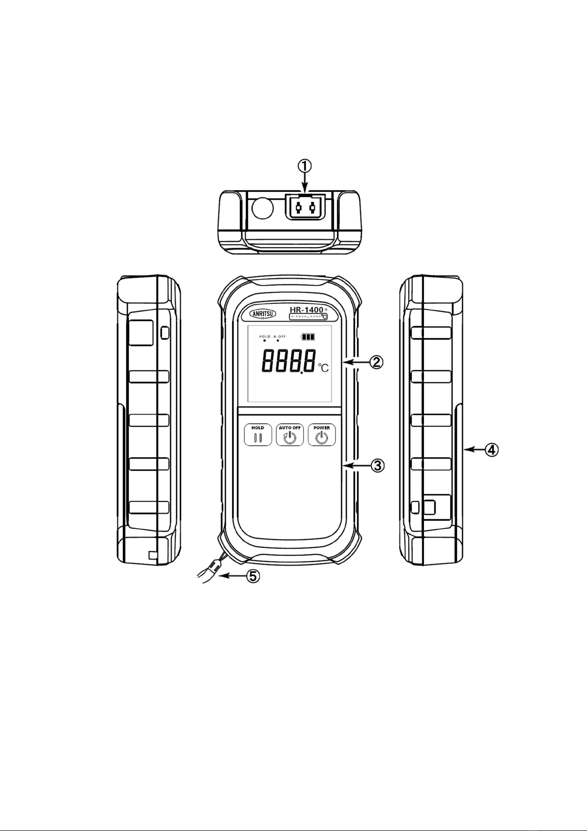
3. Name and Explanation of Each Part ................................................. 2
3.1. External View ............................................................................................. 2
3.2. Display ........................................................................................................ 3
4. Preparations Before Taking Measurements ...................................... 4
4.1. How to Install the Batteries ....................................................................... 4
4.2. How to Use the Hand Strap ....................................................................... 4
4.3. How to Set the Sensor ................................................................................ 5
4.4. How to Use the Soft Case ........................................................................... 5
5. Operations and Functions ................................................................. 6
5.1. Power ON/OFF ........................................................................................... 6
5.2. HOLD Function .......................................................................................... 6
5.3. Automatic Power OFF Function ................................................................ 7
6. Retention of Setup Data .................................................................... 8
7. Checking the Remaining Battery ...................................................... 8
8. Error Messages .................................................................................. 9
8.1. Indication of a Broken Wire of the Sensor ................................................. 9
8.2. Overrange Indication ................................................................................. 9
8.3. Battery Voltage Drop Indication ................................................................ 9
9. Maintenance .................................................................................... 10
9.1. Storage ...................................................................................................... 10
9.2. When the Case of the Instrument Gets Dirty .......................................... 10
10. Troubleshooting: Before Contacting Support .................................. 11
11. HR Series Specifications .................................................................. 12


1
1. General
This product is a handheld thermometer for high precision, reliability, and
usability. It has a high-precision analog technology and a microcomputer to
digitally correct measured data, making highly stable and high-precision
temperature measuring possible.
2. Unpacking
2.1. Unpacking
Please check if the following items are present when unpacking. We make sure
all items are carefully packed, but should you find any missing or failed items,
please contact our company or your retailer.
Item Q’ty
Applicable
model
Main unit 1 All models
Soft case 1 All models
Hand strap 1 All models
Alkaline AA battery 4 All models
Instruction manual 1 All models
Test report 1 All models
Warranty sheet 1 All models
User registration sheet 1 All models
2.2. Repacking
To move this instrument (such as transportation by car), pack it in its original
packaging. If such packaging is not available, fully protect the instrument with
shock-absorbing material (Styrofoam, etc.). Please note that if packing
materials generate dust or moisture, the instrument may become damaged.
Please use dry packing materials that do not generate dust.

2
3. Name and Explanation of Each Part
3.1. External View
(HR-1400)
① Sensor input connector
② display
③ Key switch panel
④ Battery housing
⑤ Hand strap

3
3.2. Display
Description
①
HOLD Indicator Lights when using the hold function
②
A-OFF Indicator Lights when using the auto-off function
③
Battery level Indicator
Battery level
④
Main display Main display
⑤
°C Temperature symbol
④
⑤
③
②
①

4
4. Preparations Before Taking Measurements
4.1. How to Install the Batteries
Make sure to turn the power off when replacing batteries.
Note: To maintain the waterproofing performance, firmly tighten the screws on
the battery cover.
4.2. How to Use the Hand Strap
Place the enclosed hand strap on your wrist to prevent the instrument from
dropping.
Loop the thin cord of the strap through the hole and then pull the other end of
the hand strap through that loop.
(1) Remove both
screws and
open the cover
of the battery
housing.
(2) Pay attention
to the
orientation of
the batteries.
(3) Install the
batteries.
(4) Reattach the battery
housing cover, tighten
both screws, and then
press the edge of the
cover to secure it.

5
4.3. How to Set the Sensor
Set the sensor to the main unit as shown in the illustration below. It is designed
so that if the sensor orientation is incorrect, it cannot be fully inserted. If the
sensor is forcefully inserted, failure may result. Please check the sensor’s
orientation before inserting it.
[HR-1*00] [HR-1*50]
4.4. How to Use the Soft Case
To protect the instrument from dirt or scratches, etc., use the attached soft
case.

6
5. Operations and Functions
5.1. Power ON/OFF
Pressing the POWER key will illuminate all the indicators for about three
seconds and start the measurements.
Press the POWER key again to turn the instrument off.
All illuminated Normal measurement
5.2. HOLD Function
Press the HOLD key to maintain the indicated values during measurements.
HOLD will illuminate on the screen while HOLD is on. To release the HOLD
function, press the HOLD key again.
HOLD illuminated

7
5.3. Automatic Power OFF Function
When the AUTO OFF key is pressed, “AUTO OFF” symbol will illuminate on the
screen. If no key operation is performed for a certain period of time (about five
minutes), the power will automatically be turned off, preventing the unit from
remaining turned on. To release the Automatic Power OFF function, press the
AUTO OFF key again.
“AUTO OFF” symbol illuminates

8
6. Retention of Setup Data
Some settings will be released when the batteries are exchanged or when the
instrument is turned off. Please check the details in the following table:
Function
HOLD Released
Automatic power OFF Retained
7. Checking the Remaining Battery
Remaining battery is displayed in the top right corner of the indication.
As properties vary, depending on batteries, use this value only as a reference.
Indicator
When the indication of the indicator becomes replace the batteries with
new ones.
Remaining battery
indication
FULL

9
8. Error Messages
8.1. Indication of a Broken Wire of the Sensor
If the sensor has a broken wire or is disconnected, the
burnout (broken wire) indication is displayed.
If this indication is displayed, replace the sensor with a
new one or connect the sensor.
8.2. Overrange Indication
When the temperature in measurement exceeds the
measurable range, the overrange indication is
displayed.
If the wire of the sensor is about to become broken,
this overrange indication may be shown. If it is clear
that the temperature in measurement is within the
measurable range, check the sensor.
Even if the overrange indication is shown, it will not
damage the instrument. However, the sensor may be
consumed, so relocate it to a place where the
temperature is at a heat-resistant temperature or a
lower temperature.
8.3. Battery Voltage Drop Indication
When batteries are depleted and the battery
indication on the screen becomes , replace the
batteries with new ones.

10
9. Maintenance
9.1. Storage
When storing the instrument, avoid the following places:
- In direct sunlight
- Subject to heavy vibrations
- High humidity (85%RH or more)
- High temperature atmosphere (50°C or higher)
- Filled with dust, waste, corrosive gas, and/or salt
- High electromagnetic field
To store the instrument for a long time, it is recommended to remove the
batteries and store the unit in the original packaging at time of delivery.
9.2. When the Case of the Instrument Gets Dirty
When the case of the instrument gets dirty, please wipe it with a slightly damp
cloth. Do not use alcohol, thinner, benzine, or other chemicals. Otherwise, the
case or keyboard may become discolored or deformed.

11
10. Troubleshooting: Before Contacting Support
If you find any abnormalities or become unable to operate the instrument, first
check for the following items. If you still cannot solve the issue, please contact
your retailer or our company.
(1) The instrument does not operate when power is turned on:
- Is the orientation of the batteries in the correct manner?
Reset the batteries.
- Have the batteries been depleted?
Install new batteries.
(2) The indicated values of temperature are unstable:
- Is the wire of the sensor almost broken or is the sensor deformed?
Do an appearance check of the sensor.
- Is the sensor connector inserted fully?
Re-insert the connector.
- Is the sensor sufficiently making contact with the object of measurements?
Change how to set the sensor.
- Is the measurement environment in a high electromagnetic field (such as a
large motor)?
- Relocate the instrument or use the shield.
(3) If measurement errors are too large:
- Are the thermocouple types of the sensor and the instrument the same?
Replace the sensor.
- Is the head of the sensor deformed?
Replace it with a new one.
(4) Keys are not responding:
- Is there any burn out (broken wire) indication shown?
Set the sensor.
- Are any functions running?
Terminate various functions and retry to operate the keys.

12
11. HR Series Specifications
ASP specifications (common)
Model (HR-) 1100, 1200, 1300, 1301, 1400, 1500
Operation switches Membrane keyboard (with clicking function)
Input connector ASP connector (thermocouple homogeneous metals)
Input Thermocouple Type E or K
No. of input One
Signal source resistance 1 kΩ or less
Measurement range
1°C
resolution
E -200 to 800°C
K -200 to 1370°C
0.1°C
resolution
E -104.9 to 504.9°C
K -104.9 to 504.9°C
Measurement accuracy
1°C
resolution
Less than 0°C
± (0.5% x indicated value + 1°C)
0°C or more
± (0.1% x indicated value + 1°C)
0.1°C
resolution
Less than
0.0°C ± (0.15% x indicated value + 0.2°C)
0.0°C or more
± (0.05% x indicated value + 0.2°C)
Accuracy of reference
junction compensation ±0.2°C
(
at 25°C
± 10°C)
Temperature coefficient
(Only when exceeding 25°C
± 10°C)
±0.02 × Δt°C
(Exceeded temperature Δt is multiplied by the
coefficient and then added to the indication tolerance
(measurement accuracy + accuracy of the reference
junction compensation))
Ex. @50°C
or 0°C environment: ± 0.3°C added
Operational conditions 0 to 50°C, within 0 to 80% RH (no condensation)
Storage conditions -20 to 50°C, within 0 to 85% RH (no condensation)
Sampling frequency About 200 ms
Linearizer method Digital linearizer method (compliant with JIS C 1602-
2015)
Dimensions 82.1 × 166 × 36 (W × H × D)
(Excluding connector extrusion)
Weight About 350 g (including batteries)
Analog output See specifications (analog output)
Alarm output See specifications (alarm output)

13
Power supply See specifications (power supply)
Accessories See specifications (accessories)
Conformity standards (CE)
EMC: EN61326-1: 2013
EN 61326-2-1: 2013 class A Table2 (Industrial)
RoHS: IEC EN 63000:2018
This manual suits for next models
3
Table of contents
Other Anritsu Thermometer manuals