9. INSPECTION:
ŸKEEP INSTRUCTIONS AVAILABLE FOR REFERENCE. Record Date of First Use. Prior to EACH use, inspect for
deciencies, including, but not limited to, corrosion, deformation, pits, burrs, rough surfaces, sharp edges, cracking, rust, paint
buildup, excessive heating, alteration, broken stitching, fraying, bird-caging, and missing or illegible labels. IMMEDIATELY remove
from service if defects or damage are found, or if exposed to forces of a fall arrest.
ŸEnsure that applicable work area is free of all damage, including, but not limited to, debris, rot, rust, decay, cracking, and hazardous
materials. Ensure that selected work area will support the application-specic minimum loads set forth in this instruction manual. Work
area MUST be stable.
ŸAt least at an interval of every 6 months, a Competent Person other than the user must inspect
inspections MUST be recorded in inspection log in instruction manual and on equipment inspection grid label. The Competent Person
must sign their initials in the box corresponding to the month and year the inspection took place.
ŸDuring inspection, consider all applications and hazards to which the has been subjected.
WARNING: Use of equipment in unintended applications may result in serious injury or death. Maximum 1 attachment per connection
point.
ŸRestraint: may be used in Restraint applications. Restraint systems prevent workers from reaching the
leading edge of a fall hazard. Always account for fully deployed length of lanyard/SRL. Structure must withstand loads applied in the
directions permitted by the system of at least 1,000 lbs. No free fall is permitted. Restraint systems may only be used on surfaces with
slopes up to 4/12 (vertical/ horizontal). Applicable D-rings: Dorsal, Chest, Side, Shoulder.
ŸNEVER for simultaneous use in Fall Arrest and Restraint.
10. LIMITATIONS:
ŸFall Clearance: There must be sufcient clearance below the anchorage connector to arrest a fall before to eliminate the possibility of
the user from striking the ground or an obstruction. When calculating fall clearance, account for a MINIMUM 3' safety factor,
deceleration distance, user height, length of lanyard/SRL, and all other applicable factors.
ŸSwing Falls: Prior to installation or use, make considerations for eliminating or minimizing all swing fall hazards. Swing falls occur when
the anchor is not directly above the location where a fall occurs. Always work as close as possible to be in line with the anchor point.
Swing falls signicantly increase the likelihood of serious injury or death in the event of a fall.
ŸCompatibility: When making connections with , eliminate all possibility of roll-out. Roll-out occurs when
interference between a hook and the attachment point causes the hook gate to unintentionally open and release. All connections must
be selected and deemed compatible with Rigging Plate Rope Anchors by a Competent Person. All connector gates must be self-closing
and self-locking, and withstand minimum loads of 3,600 lbs.(16 kN). See the following for examples of compatible/incompatible
connections.
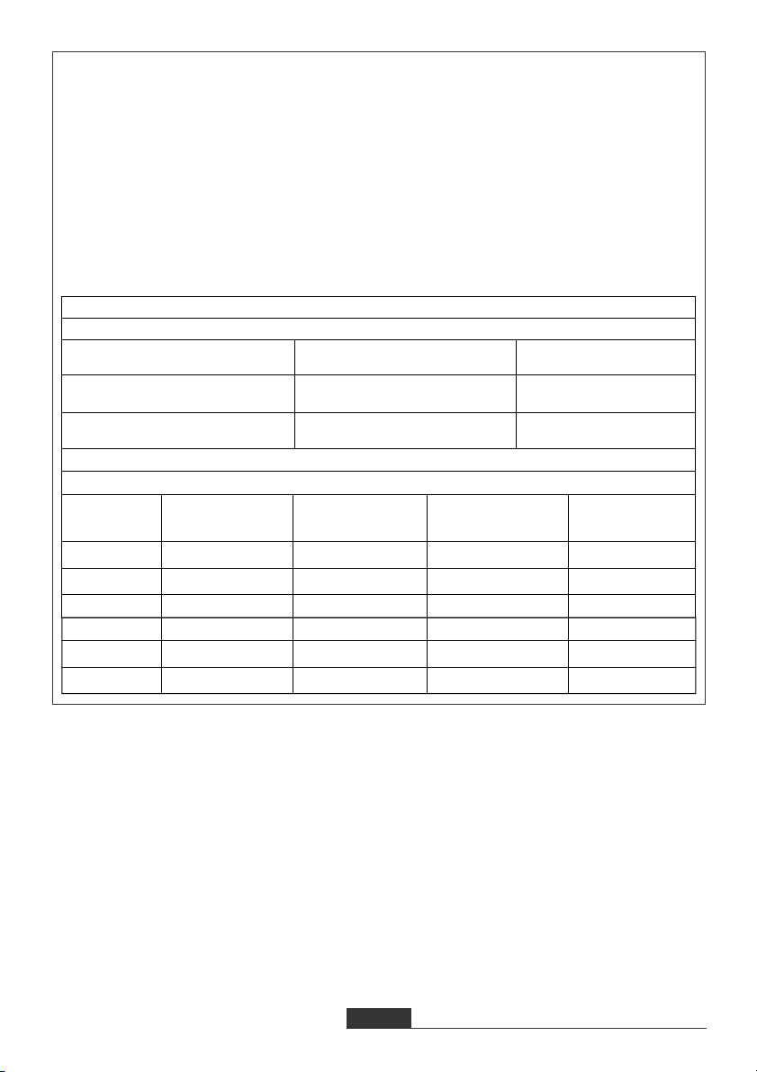
11. EQUIPMENT RECORD: If equipment fails inspection, IMMEDIATELY REMOVE FROM SERVICE. User must inspect prior to EACH
use. Competent Person other than user must complete formal inspection at least every 6 months.
12. PERSON INSPECTIONS: This inspection log must be specic to one Separate inspection logs must be
used for each All inspection records must be made visible and available to all users at all times.
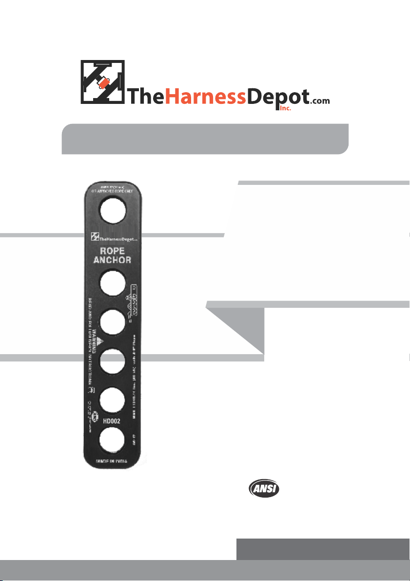
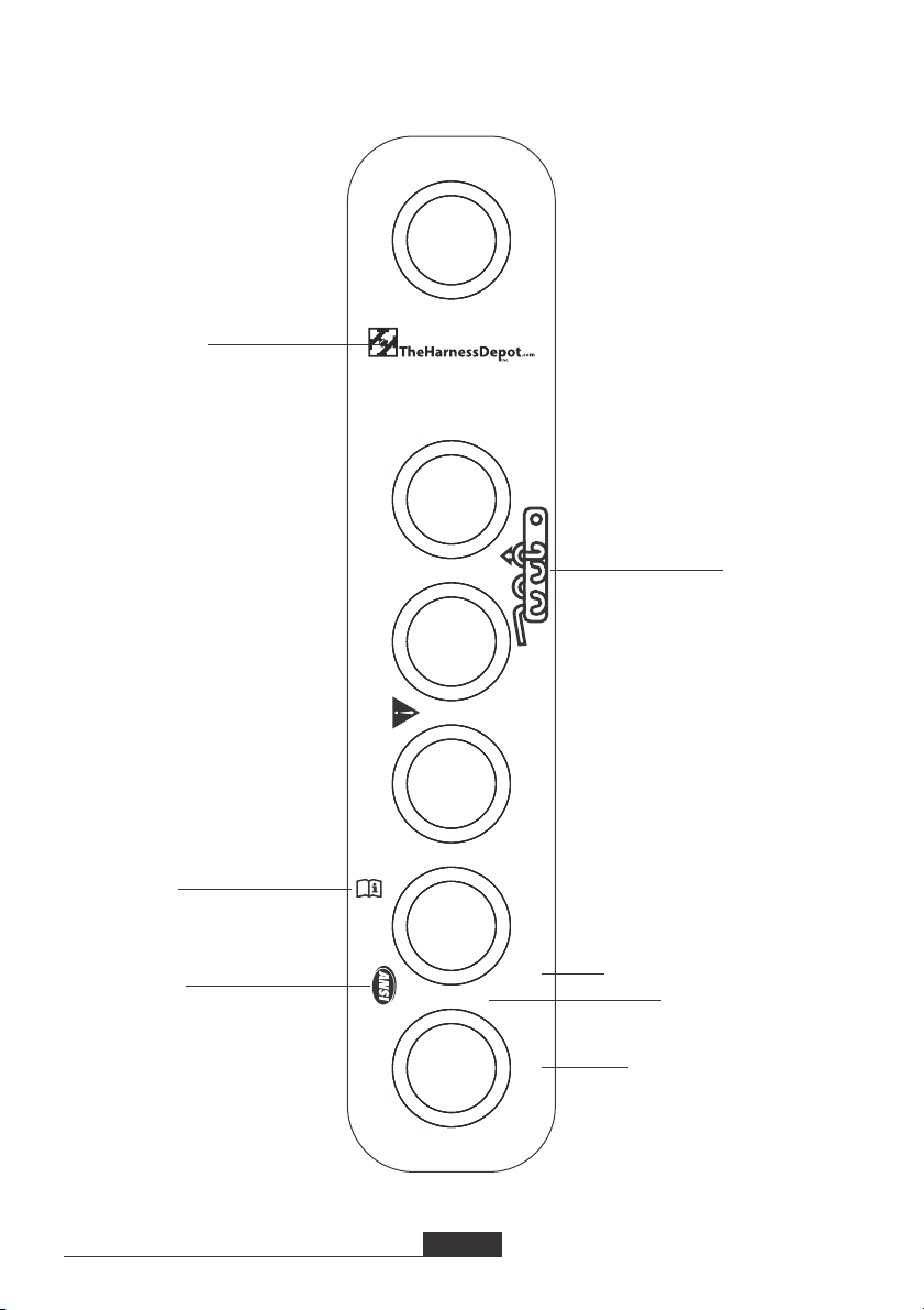
Rope Termination Anchor
Rope Termination Anchor
Rope Termination Anchor . Competent
Rope Termination Anchor
Rope Termination Anchor
Rope Termination Anchor
Rigging Plate Rope Anchors.
Rigging Plate Rope Anchors.
3