ANSI PCWB 11FT-SK Operator's manual

PCWB 11FT-SK, PCGS 10FT-SK, PCGS 60FT(R)-SK, PCGS 18FT(LE)-SK, PCGS 20FT(LE)-SK, PCWB 20FT-SK, PCGS 25FT(LE)-SK, PCGS 30FT(LE)-SK, PCWB 30FT-SK, ELE06FT-SK, ELE06FT-SKRebarUSER INSTRUCTION MANUALSELF RETRACTABLE LIFELINE This instruction manualapplies to the following models:ANSI Z359.14
MADE IN INDIA
BKLSKR 04-02

1800 lbs1800 lbs
PCWB 11FT-SK
Polyester Webbing (Black) 1" width(3.35 m)(1372 mm)
PCWB 20FT-SK
Polyester Webbing (Black) 1" width20 ft (6 m)54 inches(1372 mm)BB
1.INTRODUCTION TO RETRIEVAL TYPE FALL ARRESTER LIFELINE: SAFE KEEPER introduces the Retrieval Fall Arrester SRL in Polymer casing which is coupled with hoisting winch to enable easy retrieval of a victim of a Fall. The SRL allows the fall to arrest and also allows easy hoist of the victim with help of its hoist function.The Locking Pin on the side of the casing at the base of the handle allows this dual system to work in independent Fall Arrest & Winch modes.It can be easily mounted on the leg of SAFE KEEPER Megapod (Ref. SA17-SK) using universal mounting bracket for Retrieval SRL's.2.INSTALLATION: Follow step-1 to step-4 install this equipment:-Step 1: Install the base of universal mounting bracket on Megapod with help of two pins and lock them with the cotter pin.Step 2: Mount Retrieval SRL on the bracket by inserting the guided pulley's of Retrieval SRL into the Recess provided in the bracket.Step 3: Now insert the locking pin into the bush of bracket and tight it to the fullest.Step 4: Reel out the wire and guide it through the pulley of Megapod and connect to the Dorsal D-ring of the of the user's harness.Note: The user is advised to keep the user instructions document for the life of the product.Do not skip this instruction manual. Read the instruction manual carefully before using the equipment. If failed in doing so it may cause serious Injury or Death.This manual must be read and understood in its entirety and used as part of fall protection training program as required by OSHA or any state regularity agency. These instructions are intended to meet the manufacturer instructions as required by ANSI Z 359.14 and OSHA 1926. The user must fully understand the proper equipment use and limitations. 1Manufacturer :SAFE KEEPER, 314 E. CANAL ST. MULBERRY, FL 33860Certication Body : SATRA Technology Europe Ltd, Bracetown Business Park, Clonee, Dublin D15 YN2P Ireland (Notied Body 2777)Ongoing Assessment Body : SGS United Kingdom Ltd., Unit 202B, Worle Parkway,Weston-super-Mare, BS22 6WA, UNITED KINGDOM. (Notied Body 0120)TABLE- SPECIFICATION (ANSI SRL)Lifeline LengthMaximum Arresting ForceMaximum Arrest DistanceModel NumberLifeline Material and Size54 inches(1372 mm)10 ft(3.0 m)PCGS 10FT-SK7X19 Galvanized Steel cable (3/16" dia)1800 lbsComply ANSI Z359.14ClassB
1800 lbs
PCWB 30FT-SK
Polyester Webbing (Black) 1" width30 ft (9.14 m)54 inches(1372 mm)B
1800 lbsELE 06FT-SKRebarTechnora Webbing (Black) 0.8" width6 ft (1.83m)24 inches(609 mm)A1800 lbsELE 06FT-SKTechnora Webbing (Black) 0.8" width6 ft (1.83m)24 inches(609 mm)A11 ft

3.INTRODUCTION TO LEADING EDGE SELF RETRACTABLE LIFELINE: Each SRL in this range is constructed in such a way that if subjected to contact with a sharp edge in the event of a fall from a roof/ terrace etc, the retracted lanyard remains intact, while arresting the fall immediately. Conforms for the vertical usage as per ANSI Z 359.14-2014 and Horizontal usage as per ANSI Z 359.14-2014 SRL-LEŸConnect the end of Lifeline, adjacent to Energy Absorber, to the dorsal attachment of the body support.ŸLE range of SRL's are tested and suitable to be used on edges having radii not greater than 0.005".4.POSSIBLE USAGE FOR ELECTRON RETRACTABLE FALL ARRESTER: * It can be used where the Anchorage point is available at foot Level also. (Refer g 01)How to Use: Follow below steps to use this equipment as single or double Lanyard. (Refer g 02)STEP 1: Connect the swivel eye of the retractable fall arrester to the dorsal attachment of the full body harness with the help of special connector PN 170 and PN 169 & ensure the connector is locked.STEP 2: Now connect the snap/scaffold hook at the termination end of the device to the structure and ensure that it is locked. You are now safe to move in normal speed. In the event of a fall, the Retractable Fall Arrester locks & also minimizes the impact forces on the body of user.Similarly, it can be used where the anchorage point is available at foot level by just connecting the swivel eye of the retractable to the anchorage point and the hook at termination to the dorsal attachment of harness.Fig 02Fig 01LIST OF RETRIEVAL TYPE LEADING EDGE FALL ARREST SRL's Model NumberLifeline Material and SizePCGS 30FT LE-SK7X19 Galvanized Steel cable ( dia)7/32" PCGS 20FT LE-SK7X19 Galvanized Steel cable ( dia)7/32"Lifeline Length30 ft (9.14 m)20 ft (6.09 m)Weight15.19 lbs8.9 lbs3.HOW TO USE ELECTRON AS TIE-BACK: SAFE KEEPER Electron with Tie-back hook should be used with the SRL casing attached to the Dorsal D-ring of the full body harness, and the extended webbing (with a sheath) wrapped around the anchorage structure, and the Tie-back hook secured around the webbing. WARNING:ŸNEVER use Electron Tie Back SRL in Leading Edge (LE) applications.ŸALWAYS avoid lifeline contact with sharp or abrasive edges and surfaces.ŸFor Tie – Back application, snap hook must only be attached to webbing below shock pack. NEVER attach snap hook between housing and shock pack.ŸNo Free Fall is allowed2Lifeline LengthMaximum Arresting ForceMaximum Arrest DistanceModel NumberLifeline Material and SizeComply ANSI Z359.14ClassLIST OF RETRIEVAL TYPE RETRACTABLE FALL ARREST SRL's PCGS 60(R)-SKFT7X19 Galvanized Steel cable (3/16" dia)60 ft (18 m)54 inches(1372 mm)1800 lbsB7X19 Galvanized Steel cable ( dia)7/32"18 ft (5.48 m)7.5 lbs7X19 Galvanized Steel cable ( dia)7/32"25 ft (7.62 m)9.0 lbs PCGS 18FT LE-SK PCGS 25FT LE-SK

Installation and use ŸEnsure that the structural anchor to which Electron Tie-Back SRL is to be attached, and on which work is to be performed, is free of all hazards, including, but not limited to, debris, rot, rust, sharp or abrasive edges and surfaces, and hazardous materials. Ÿ Wrap Tie- Back SRL lifeline around selected structural anchor, and attach snap hook on to webbing below shock pack (Never attach snap hook between housing and shock pack). Attach Electron Tie-back carabiner to applicable harness D-ring. WARNING:If the Electron with rebar hook conguration is used, then the rebar hook should always be connected to the anchorage structure, and NEVER to the dorsal D-ring of the full body harness. And the Electron casing should always be worn at the harness end. A competent person must always ensure compatibility of the anchorage structure with the Electron.5.GENERAL REQUIREMENTS, WARNINGS AND LIMITATIONS:ŸThe Equipment is designed for use as a part of a personal fall protection system. Components must not be used for any other operation other than that which it has been designed and approved. Fall Arrest system are designed to comply with OSHA. Fall Restraint System must be designed by a Qualied Person, and must be installed and used under the supervision of a competent person. ŸAll authorized persons/users must refer the regulations governing occupational safety, as well as applicable ANSI or CSA standards. Please refer to product labeling for information on specic OSHA regulations, ANSI and CSA standards met by product. ŸProper precautions should always be taken to remove any obstructions, debris, material, or other recognized hazards from the work area that could cause injuries or interfere the operations of the system. All equipment must be inspected before each use according to the manufacturer's instructions. All equipment should be inspected by a qualied person on a regular basis.ŸTo minimize the potential for accidental disengagement, a competent person must ensure system compatibility.ŸEquipment must not be altered in any way. Repairs must be performed only by the manufacturer, or persons or entities authorized in writing by the manufacturer.ŸAny product exhibiting deformities, unusual wear, or deterioration must be immediately discarded. Any equipment subject to a fall must be removed from service. The authorized person/user must have a rescue plan and the means at hand to implement it when using this equipment.ŸNever use fall protection equipment for purposes other than those for which it is designed. Fall protection equipment should never be used for towing or hoisting.ŸAll synthetic material must be protected from slag, hot sparks, open ames, or other heat sources. The use of heat resistant materials is recommended in these applications.ŸNever use natural materials (manila, cotton, etc.) as part of a fall protection system.ŸDo not expose this equipment to chemicals which may have a harmful effect on the materials used to construct it. Be especially aware of caustic environment, or those that contain high levels of organic acids or bases. If you are uncertain about the safe Shock PackStructural Anchor (I –beam)Snap HookTo this eye hole, attachcarabiner to applicable harness3

operations of this equipment in any environment, contact SAFE KEEPER for further instructions.ŸDo not use the equipment near sharp edges and abrasive surfaces. ŸDo not use the equipment around moving machinery or electrical hazards. ŸSAFE KEEPER Self Retractable lifeline should be used only with the combinations of components, sub-systems or both which may not affect or interfere with the safe function of one another. Be certain that connecting devices are compatible and that other elements of the PFAS are safe to use and compatible before use.6.TRAINING REQUIREMENTS: The employer must provide a training program to each employee who might become exposed to fall hazards. The program must enable each employee to recognize the hazards of falling and must train to follow each employee in the procedures in order to minimize these hazards. Relevant Federal, State, and local requirements, procedures, and standards must also be a part of training.The employer must ensure that each employee has been trained, as necessary, by a Competent or Qualied Person in the nature of fall hazards in the work area, the correct erecting, maintaining, disassembling, and inspection of the fall protection systems being used, and the use of personal fall arrest systems.7.RESCUE PLAN:The user is required to have a rescue plan and the means at hand to implement the plan when using the equipment. 8.EQUIPMENT IS SUBJECTED TO A FALL: Remove the equipment from service immediately if it has been subjected to the force of a fall arrest. Contact your distributor or SAFE KEEPER about policies regarding replacement of SAFE KEEPER components involved in a fall incident.Inspection:ŸOnly the manufacturer of this equipment or persons or entities authorized in writing by the manufacturer must repair the fall protection equipment.ŸThe date of rst inspection should be recorded by the employer on the equipment, and any serial number must be recorded on the owner's Inspection Log.ŸFormal inspections must be made either by a Competent or a Qualied Person on (at least) a semi-annual basis.Prior To Each Use:Ÿ Fall protection equipment must be inspected by the user for defects, damage, or deterioration.Ÿ Any suspected defective equipment must be removed from service immediately.Ÿ If the manufacturer's label is not legible or is missing, the equipment must be removed from service.Ÿ Fall protection equipment must be removed from service upon evidence of defects, damage, or deterioration, or upon expiration of the manufacturer's specied service limits, whichever comes rst.9.MAINTENANCE, CLEANING, AND STORAGE: Repairs to equipment must be administered only by a SAFE KEEPER representative or person or entity authorized by SAFE KEEPER. Contact SAFE KEEPER to request equipment maintenance and/or repair. Cleaning after use is important for maintaining the safety and life of the equipment. Clean the equipment of all dirt, corrosives, and contaminants. If the equipment cannot simply be wiped clean use a mild soap and water. Rinse, wipe, and hang to dry. Store equipment where it cannot be affected by heat, light, excessive moisture, oil, chemicals, or other degrading elements.WARNING: Consult with your doctor if there is reason to doubt your tness to safely absorb the shock from a fall arrest, Age, tness, and health conditions can seriously affect a worker's ability to withstand falls. Pregnant women and minors must not use any SAFE KEEPER Fall Protection equipment.4

10. DESCRIPTION OF PRODUCT:Retractable: All SAFE KEEPER Retractables are hereby referred to as Self Retracting Lifelines (SRL). The device is used to safely expand the working area where a harness with a 6 ft. lanyard is not adequate. Also, a SRL is designed to reduce the shock loading to the body of a worker by limiting the distance of a fall. The device allows for complete freedom of movement. This product is to be used as part of a complete fall arrest system. PFAS normally include the use of a full body harness, anchorage connector such as a carabiner and the SRL.ABCDEFGHIJKLMNRATCHET CASING PLAIN CASING ANCHORAGE EYE GALVANIZED WIRE ROPE Ø5mmx15m SNOUT FERRULE DAMPER SPRING GUIDEDAPMPER SPRING CAP DAMPER SPRING FERRULE SWIVEL STEEL SNAP HOOK ( 122) WEBBING 25mm WEBBING GUIDE SWIVEL STEEL SNAP HOOK (144) ITEM/ DESCRIPTION S.NO.PART LIST SAFE KEEPER Self Retracting Lifeline: Includes a swivel eye anchorage, self-locking swivel snap hook with impact indicator, and 3/16" galvanized wire cable/1" Polyseter Webbing. SRL also comes with a carabiners and tag line to be used with the device to avoid improper use.11.PRODUCT APPLICATION INFORMATION: The SRL is used in a stationary or mobile manner. As a stationary device, the SRL would be mounted to an approved xed anchorage connector directly overhead. The SRL would extend as the user moves away from the anchor point and it retracts as the user moves back towards the anchorage point. As the SRL is used in a mobile manner, the device should be traveling on a steel cable, rope or xed rail traveling from one anchorage connector to the other.12.LIMITATIONS: Consider the following application limitations before using this equipment.ŸCapacity: The SRL is to be used by an individual with a combined weight (person, clothing, tool, etc.) of 90 lbs.(41 kg) minimum and no more than 310 lbs.(140 kg) maximum. No more than one person may be connected at one time.ŸCorrosion: Leaving the SRL in an environment for long periods of time that could cause corrosion of metal parts is not warranted in any way and must not be done. Use caution when working around corrosive compounds such as ammonia, sewage, fertilizers, seawater or other corrosive environments. when using in such environment the product may require more frequent inspections or servicing. These increased inspections and servicing are required to ensure corrosive damage is not impacting the performance of the SRL.ŸChemical Hazards and Heat: Extreme caution must be taken when working in or around environments containing acid or caustic chemicals, particularly at elevated temperatures. Damage will result to in this environment. Chemical damage is difcult to detect and it is recommended that the lifeline be replaced periodically to ensure safety of the workers.Additionally, this SRL is not to be used in high temperature environments. The SRL must be protected when using near welding, metal cutting, or similar activities. Hot sparks and slag can damage this equipment. Users must inspect SRL prior to each use.Ÿ Electrical Hazards: For web and wire rope models, there is a possibility of an electric current owing through the lifeline. Moisture absorbed by the lifeline may provide a path for electrical current to ow, resulting in electrical shock. Use caution where the lifeline may contact high voltage power line.Ÿ Locking Speed: Extreme caution should be taken when using this device whereas an obstructed fall could occur as well as when someone must perform work in a conned or cramped space. Working in these types of environments could limit the speed at which the locking mechanisms engage. Extreme caution should be taken when working on low pitched roofs, where a worker may slide instead of fall. A clear path is required to ensure positive locking of the SRL.5

Considers when calculating distance:ŸDistance of DecelerationŸMovement of harness attachment element (D-ring)ŸFree Fall DistanceŸWorker Height (Worker's height could affect the free fall distance)ŸElevation of Anchorage ConnectorŸLengths of Connecting SubsystemsAttach to OverheadAnchor!Swing Falls IncreaseFall Arrest Distance13.LIMITATIONS CONTINUED:ŸSwing Falls: Swing falls occur when the anchorage point is not directly above the point where a fall occurs. The force of striking an object in a swing fall may cause serious injury or death. Minimize the risk of a swing fall by working as close to the anchorage point as possible. Do not permit a swing fall if injury could occur. Swing fall will signicantly increase the clearance required when a self retracting lifeline or other variable length connecting system is used.ŸPotential Environmental Hazards: Use of fall protection equipment in areas with environmental hazards may require additional precautions to prevent injury to the user or damage to the equipment.Hazards may include but are not limited to: chemicals, corrosive environments, high voltage power lines, gases, moving machinery, and sharp edges.14.APPLICABLE STANDARDS: Refer to potential applicable standards. Standards might include OSHA regulations depending on the type of work, and also might include state regulations where applicable. Consult regulatory agencies for more information on personal fall arrest system and associated components. This product is designed to comply with OSHA and ANSI Z359.14 standards when used properly, and in accordance with manufacturer's instructions.15.SYSTEM REQUIREMENTS:ŸCompatibility of Components: SAFE KEEPER Fall Protection equipment is designed to be used with SAFE KEEPER approved components. Please contact SAFE KEEPER if you have a question regarding compatibility. Making substitutions without approval from SAFE KEEPER Protection may lead to injuries and or death by compromising the safety and reliability of any component or that of the complete system. A qualied and competent person can make a determination on compatibility of equipment from different manufacturers. If in doubt, please contact SAFE KEEPER Fall Protection for clarication.ŸCompatibility of Connectors: Connectors (D-rings, hooks, carabiners) must be capable of supporting at least 5,000 lbs. (22kN). Do not use equipment that is not compatible. Non-compatible connectors may unintentionally disengage. Self locking snap hooks and carabiners are required by ANSI and OSHA. Connectors must be compatible in size, shape, and strength.ŸMaking Connections: Only use self-locking snap hooks and carabiners with any SAFE KEEPER Fall Protection equipment. Do not use equipment that is not compatible. If you have any questions on compatibility, please contact SAFE KEEPER.WARNING:Large throat opening snap hooks should not be connected to standard size D-rings or similar objects which will result in a load on the gate if the hook or D-ring twists or rotates. Large throat snap hooks are designed for use on xed structural elements such as rebar or cross members that are not shaped in a way that can capture the gate of the hook.Max 7.5 Feet Fall clearanceTotal Fall Distance (Free Fall + Deceleration)6

7ŸŸThe “arrest distance” experienced through testing, internally or externally is indeed 120”, then clear fall requirement would be 18ft, calculated and measured as follows:Ÿ120” -arrest distance measured from walking/working surface to the hook attachment point to the test weight.Ÿ60” -Distance that needs to be added for the length of an average worker measured from d-ring to feet.Ÿ36” -3ft safety factor to include D-ring slide/harness give and buffer to ground below.Ÿ216”-(18ft) required clear fall as measured from the walking/working surface to the nearest obstruction/ground below.ŸTherefore, for all SRD-LE's, we need to make clear that “clear fall” is measured from the walking/working surface to nearest obstruction/ground below.ŸStandard SRL (When Used Vertically) Clear Fall IssueŸType AŸ24” – Maximum Arrest DistanceŸ36” 3ft safety factor to include D-ring slide/harness give and buffer to ground below.Ÿ60” (5ft) required clear fall as measured from the walking/working surface to the nearest obstruction/ground belowŸType BŸ54” – Maximum Arrest DistanceŸ36” 3ft safety factor to include D-ring slide/harness give and buffer to ground below.Ÿ96” (7.5ft) required clear fall as measured from the walking/working surface to the nearest obstruction/ground belowLeading Edge Clear Fall Leading Edge SRLSharp Edge16. PERSONAL FALL ARREST INFORMATION:Personal Fall Arrest System (PFAS): Personal fall arrest systems used with this equipment must meet applicable state, federal, OSHA, and ANSI requirements. A full body harness must be worn when this equipment is used as a component of a personal fall arrest system. As required by OSHA, the personal fall arrest system must be capable of arresting the user's fall with a maximum arresting force of 1,800 lbs., and limit the free fall to six feet or less.WARNING:
Do not alter or intentionally misuse this equipment. Consult with SAFE KEEPER when using this equipment incombination with
components or subsystems other than those described here in this manual and or other information. Use caution when using this equipment around moving machinery, electrical and chemical hazards, and sharp edges.

17.OPERATION, USE AND PLAN:ŸAnchorage: The anchorage to which the SRL is attached must sustain static loads applied in the directions permitted by the fall arrest system of at least 3,600 lbs. with certication of a qualied person, or 5,000 lbs. without certication. Refer to OSHA and ANSI for specic denition. This device is only to be used by one person. When more than one personal fall arrest system is attached to the same structure, the strength requirements stated above must be multiplied by the number of personal fall arrest systems attached to the structure.ŸHorizontal Systems and Tripods: In applications where the SRL is used in conjunction with a horizontal system or with Megapod, ensure the support structure and or the horizontal system components are compatible.ŸHorizontal systems must be designed and installed under the supervision of a qualied engineer.Ÿ Anchorage Selection: Select an anchorage point capable of support is at least 5,000 lbs. Additionally, select a location for anchorage of the SRL that will avoid a free fall and swing fall hazards. To prevent an increased free fall distance, do not work above the anchorage location.ŸFree Fall: Avoid slack in the line and do not lengthen the SRL by connecting a lanyard or other snap hooks directly to the retractable.ŸDo not use this device at or below your feet. This will increase your free fall distance beyond the allowable limits set by OSHA and exceed the capabilities of the SRL to safely arrest a fallŸ Swing Falls: Swing fall will occur when the anchorage point is not directly over the head of the worker or directly above the point where a fall occurs. The force of striking an object in a swing fall may cause serious injury including death. Minimize swing falls by working as directly below the anchorage point as possible. In all situations where a swing fall can occur, the likelihood of an injury can occur. Please contact SAFE KEEPER Fall Protection if you have questions on a particular application involving one of our retractable.Ÿ Fall Clearance: Ensure that there is always adequate clearance in the path of a fall to avoid striking an object or lower level. A minimum of six feet from the working level to the lower level or nearest obstruction is recommended as long as the SRL is attached directly over head of the worker and the worker is not in danger of insult as a result of a swing fall hazard.ŸSharp Edges: Unprotected and sharp edges can damage the lifeline. Please make sure to avoid working where this can occur and provide protection where possible. A SAFE KEEPER manufactured energy absorbing device can be added to aid in reducing the impact forces on the entire device. For more details contact SAFE KEEPER.18.INSPECTION OF SELF RETRACTING LIFELINES:ŸBefore each use of this equipment inspect it according to the following guidelines: A formal inspection of fall protection products/components must be performed at least every six months by a competent person other than the user. The frequency of formal inspections should be based on conditions of use or exposure. Record the inspection results in the inspection and maintenance log at the end of this manual. OSHA 1910.66, OSHA 1926.502 and ANSI Z359.14 requires an inspection of equipment before each use. Before using this equipment, record the serial number information from the label in the inspection and maintenance log at the end of this manual.ŸAnnually: ANSI requires a formal inspection of the SRL be completed by a competent person other than the user at least twice a year. More formal and frequent inspections may be required based upon the severity and environmental conditions of the workplace. SAFE KEEPER Retractable, unless otherwise marked, are required to be recertied every two years from the date of rst use.WARNING:If inspection reveals an unsafe or defective condition, remove the product from service and send product back to SAFE KEEPER authorized service center.8

STEP
1
STEP
2
STEP
7
STEP
8
STEP
9
STEP
5
STEP
6
STEP
3
STEP
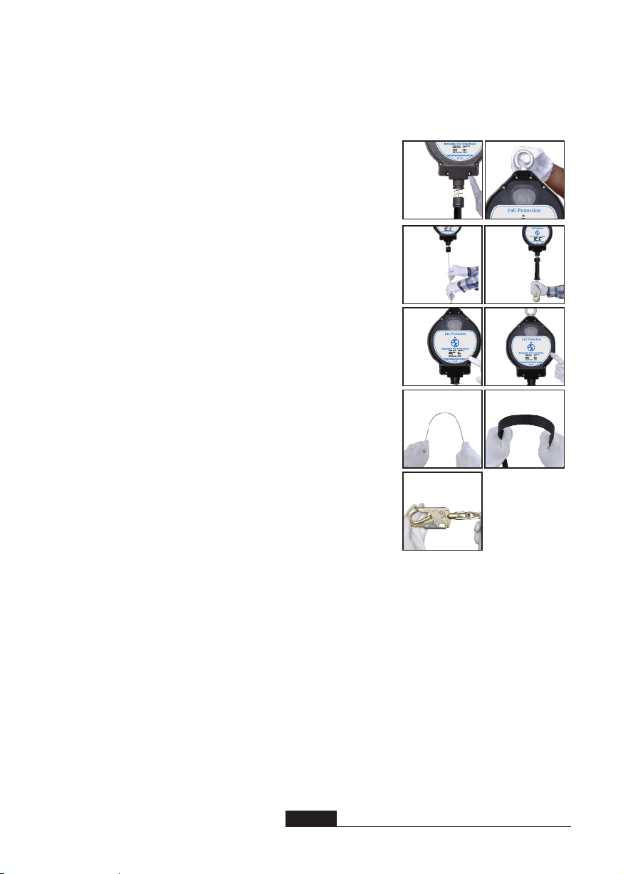
4ŸAfter a Fall Arrest: Inspect the impact indicator on the snap hook of the SRL and look for an exposed red color band. Do not attempt to reset the impact indicator. Remove the retractable from service immediately and return to SAFE KEEPER or an authorized repair center. If using a retractable with a webbed lifeline, then inspection of the shock pack is required. Remove retractable from service if there are any deformation, elongation or other signs of the shock pack being torn or deployed. If inspection reveals an unsafe condition, remove unit from service immediately and destroy, or contact an authorized service center for repair.ŸInspecting The Self Retracting Lifeline:STEP 1: Inspect for loose screws and bent or damaged parts.STEP 2: Inspect housing for distortion, cracks or other damage Ensure the swivel eye is not damaged or distorted in anyway. Make sure the swivel eye turns freely.STEP 3: The lifeline must fully extend and retract without hesitation or creating a slack line condition.STEP 4: Ensure the device locks up when lifeline is jerked sharply.STEP 5: Ensure the labels must be present and fully legible with inspection log information completed.STEP 6: Look for signs of corrosion on the entire unit.STEP 7: Wire rope inspection must include identifying cut kinks, broken wires, bird-caging, corrosion, welding splatter, chemical damage, or severely abraded areas. Check all thimbles etc… for excessive wear including cracks or separation of metal components.STEP 8: Webbed lifeline inspection must include identifying frayed strands, broken webbing, burns, cuts, and abrasions. Inspect for excessive heat, paint build-up, soiling rust, or chemical damage indicated by brown or discolored areas.STEP 9: Inspect connecting hooks or carabiners for signs of damage, corrosion or excessive wear.STEP 10: Record inspection results in the inspection and maintenance log found in this manual. Clearly check off month the SRL was inspected on the label of the housing.19.CABLE INSPECTION: When inspecting SRL's that utilize cable lifelines, it is critical to look for the following damages and deterioration that will result in malfunction of the unit and potentially unsafe conditions.Ÿ Crushing: The cable will often get crushed or bent while being used on a job site. Cable that is crushed or bent will damage the retractable and thus the
unit should be immediately taken out of service and returned to SAFE KEEPER or
authorized repair center.ŸCutting: Movement over sharp edges or other objects while the cable is under tension results in damaged strands and broken wires. If, through inspection of the retractable lifeline prior to each use, it is found to have any broken strand, immediately remove from service and return to SAFE KEEPER or an authorized repair center.ŸAbrasion: Abrasion can result from normal wear. Particular attention must be paid to the outer wire strands as they with each use, it is found have damage or deterioration from abrasion, immediately remove from service and return to SAFE KEEPER or an authorized repair center.ŸKinking: Any deformation in the cable whereas the lifeline appears to be bent, requires the retractable to be immediately removed from service and returned to SAFE KEEPER or an authorized repair center.ŸCorrosion, Arc or Heat Damage: Extreme caution must be taken to avoid any potential damage as a result of using a retractable within an environment where corrosive compounds, welding, or high heat may exist. Corrosive damage could cause the cable to crack. Welding damage would result in fused wires and thus change the characteristics of the strength with regards to the wire. If the retractable is used in these environments, the retractable lifeline needs to be closely examined for damage. 20.PLAN THE FALL PROTECTION SYSTEM: Before installation plan your system. Consider all factors that will affect your safety during use of this equipment. The following list gives important points to consider when planning your system:ŸAnchorage: Select a rigid anchorage capable of supporting the loads no less than 5,000 lbs per worker attached.ŸSharp Edges: Avoid working where system components may be in contact with, or abrade against, unprotected sharp edges.9

MADE IN INDIA
ŸAfter a Fall: Components which have been subjected to the forces of arresting a fall must be removed from service and destroyed. Retractable must be returned for servicing to SAFE KEEPER or an authorized repair center.ŸRescue: The employer must have a rescue plan when using this equipment. The employer must have the ability to perform rescue quickly and safely.21.INSTALLATION REQUIREMENTS: The following requirements outline the proper installation procedures to be followedŸLocation:ŸSelect a location on an appropriate strength anchorage that will provide overall safety and proper loading. The anchorage must be free of deformities or defects that may weaken the structure. The anchorage to which the SRL is attached must be capable of sustaining static load in the directions applied by the personal fall arrest systems of at least 3,600 lbs. with certication of a qualied person, or 5,000 lbs. without certication.ŸWhen more than one person is attached to the same structure, the strength requirements stated above must be multiplied by the number of personal fall arrest systems.ŸDo not work above the anchorage point. While using an SRL, always ensures that there is constant tension on the cable. Slack in the cable could result in an increase in fall distance. Movenormally as sudden jerky movements will allow the locking mechanism to engage.ŸDo not install in an area where a swing fall hazard potentially could exist. Failure to do so can result in injury or possibly death.ŸKeep these instructions for reference.WARNING:If inspection reveals an unsafe or defective condition, remove the Self Retracting Lifeline from service and send it back to SAFE KEEPER or an authorized repair center.Training: It is the responsibility of the user and the purchaser of this equipment to assure that they are familiar with these instructions, trained in the correct care and use of, and are aware of the operating characteristics, application limits, and the consequences of improper use of this equipment.WARNING:Training should be conducted without exposing anyone to a fall hazard. Training should be repeated on a periodic basis in accordance with your organization policy and compliance with OSHA regulations.ONE OR MORE OF THESE LABELS WILL APPEAR ON YOUR PRODUCT10

WARNING::ŸTo maintain the longetivity of the self-retractable blocks, SAFE KEEPER strongly recommends to get them serviced at a SAFE KEEPER Authorized Service Centre only. If not, SAFE KEEPER shall not be liable for any warranty claims.ŸAlternation or misuse of this product or failure to follow instructions may lead to serious injury or even death. 11
Made In India

LIFESPAN: The estimated product Lifespan is 10 years from the date of manufacturing. The following factors can reduce the Lifespan of
the product: intense use, contact with chemical substances, specially aggressive environment, extreme temperature exposure, UV exposure, abrasion, cuts, violent impacts, bad use or maintenance.
DISCLAIMERS: This information on the product is based upon technical data that SAFE KEEPER obtained under laboratory conditions and believes to be reliable. SAFE KEEPER does not guarantee results and take no liability or obligation in connection with this information. As conditions of end use are beyond our control it is the user's responsibility to determine the hazard levels and the use of proper personal protective equipment. Persons having technical expertise should undertake evaluation under their own specic end-use conditions, at their own discretion and risk. Please ensure that this information is only used to check that the product selected is suitable for the intended use. Any product that is damaged, torn worn or punctured should be discontinued from usage immediately.
Periodic examinationnext due date Product Model & type/Identication Trade NameAddress Identication number Manufacturer Tel, fax, email into use Year of manufacture Purchase Date Date rst put into use Other relevant information (e.g. document number) PERIODIC EXAMINATION AND REPAIR HISTORY Date Name and signature of competent personReason for entry (periodic examinationor repair)Defects noted, repairs relevant information carried out and otherEQUIPMENT RECORD12

SAFE KEEPER, 314 E. CANAL ST. MULBERRY, FL 33860
This manual suits for next models
15
Table of contents
Other ANSI Safety Equipment manuals
Popular Safety Equipment manuals by other brands

LAHTI PRO
LAHTI PRO LPAB64S User instructions

PREISING
PREISING PASA I Series Instructions for use

Steitz
Steitz ESD Officer 2 User information

BACOU USA SAFETY
BACOU USA SAFETY Survivair TWENTYTWENTY HEADNET 962270 INSTALLATION AND ORIENTATION PROCEDURES

Restube
Restube Lifeguard instruction manual

ABS
ABS ABS-Lock X-DURCH instruction manual