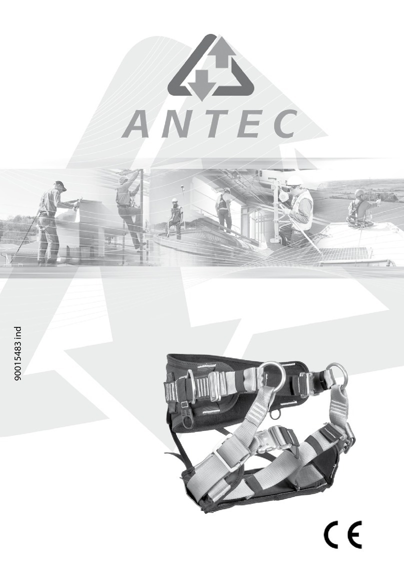
Antec ABIES User manual

1
90016729 ind A

Notice d’utilisation
de l’Abies
1015414 - CEINTURE ELAGAGE ABIES EN 358-813 S/M
1015415 - CEINTURE ELAGAGE ABIES EN 358-813 M/L
MATÉRIAUX UTILISÉS :
Sangle principale : polyester, point central : polyamide, dosseret : cordal.
CARACTÉRISTIQUES:
Ceinture d’élagage conforme à l’EN 358 et l’EN 813, composée de 2 anneaux latéraux pour le maintien au
travail (EN 358), de cuissardes semi-rigides à boucles automatiques et d’1 point central en corde
démontable (EN 813).
INSTRUCTIONS DE RÉGLAGE DE L’ABIES :
Avant toutes choses libérer les sangles de réglage de la triangulation (4 pour les sangles de cuisse, 2 pour
les sangles du dosseret).
Ouvrir au plus large les réglages : de triangulation de dosseret, des sangles des cuissardes et des quatre
élastiques de soutien de cuissardes.
Instaler un rappel d’élagage muni de son nœud autobloquant à 5-6m de hauteur.
1/ RÉGLAGE DE LA SANGLE DE CEINTURE ET POSITIONNEMENT DU DOSSERET
Placer le dosseret au niveau de la ceinture dans le creux des reins, le centrer. Ajuster la «sangle de
ceinture». Le dosseret ne doit pas pouvoir glisser sous les hanches.
1
2
10
9
8
5
7
6
4
3
10
1- Point central avec anneau
2-Boucles automatiques
cuissardes avec protection
3-Boucle automatique ceinture
4-Maniles
5-Anneaux latéraux
6-Elastiques de maintien
cuissardes
7-E m p l a c e m e n t s p o r t e
tronçonneuse
8-Porte matériel
9-Cuissardes
10-Dosseret

3
2/ RÉGLAGES DES CUISSARDES
Les cuissardes ont pour fonction l’assise du grimpeur. Eles supportent plus ou moins 70% de son
poids.
2.1 Tout en restant les pieds au sol s’instaler dans le rappel avec son nud autobloquant. (Fig 1)
2.2 Se mettre en opposition, le rappel formant un angle de 45 ° environ par rapport à la verticale du
point d’ancrage. (Fig 1)
2.3 Positionner les cuissardes sous les cuisses. (Fig 2)
2.4 Régler la longueur des sangles des cuissardes de façon :
- à ne pas être trop serré au niveau des cuisses,
- à garder le point central réglable ou xe au plus près.
Il est important que la coque
rigide des cuissardes soit bien
centrée sous la cuisse (Fig 2)
Pour se faire le réglage
des deux sangles
sur chaque cuissarde
doit être symétrique.
NB : A ce stade de réglage,
il est normal
que le dosseret
ne soutienne pas le dos.
3/ RÉGLAGES DU DOSSERET
Le dosseret a pour fonction le maintien du dos. Il
empêche le grimpeur de partir en arrière. Il supporte
plus ou moins 30% du poids du grimpeur.
3.1 Rester en opposition comme au chapitre 2.2 (Fig 1)
3.2 Serrer les sangles de réglage de triangulation du
dosseret de manière à se sentir soutenu dans le dos. (Fig 3)
3.3 Se mettre en suspension complète, aner le
réglage du dosseret de façon à être soutenu dans le dos.
Un compromis entre l’opposition et la suspension complète est à trouver.
4/ RÉGLAGES DES QUATRE ÉLASTIQUES DE SOUTIEN DE CUISSARDES
Ces élastiques servent à maintenir les cuissardes en place lorsque le grimpeur ne se trouve pas en opposition.
4.1 Se remettre en opposition avec le rappel en formant un angle de 45 ° environ par rapport à la
verticale du point d’ancrage. (Fig 1) Bien positionner les cuissardes sous les cuisses comme au
chapitre 2 .3. (Fig 2)

4
4.2 Ajuster au plus court les quatre élastiques (Fig 4)
4.3 Le réglage est correct si lors du passage de la
position debout à la position assise les cuissardes
se calent seules sous les cuisses. Du passage
assis à debout les cuissardes ne doivent pas
tomber au milieu des cuisses.
5/ AFFINAGE DES RÉGLAGES
5.1 Contrôler la symétrie des longueurs de réglage.
5.2 Passer le surplus de sangle dans la fente de la boucle.
S’assurer que le retour de sangle couvre le mot «
DANGER « et que la èche jaune sorte du dernier
passage. (Fig 5-A)
5.3 Ranger le mou des sangles dans les élastiques prévus à cet eet. (Fig 5-B)
5.4 Le surplus de sangle des boucles automatiques de cuissardes se range à l’intérieur des protections. (Fig 6)
6/ LE POINT CENTRAL RÉGLABLE
Le point central réglable permet d’ajuster la longueur du point central au besoin du grimpeur (position
longue en footlock ou retour de branche (Fig 7) et position courte en déplacement dans le tête de l’arbre (Fig 8)).
Ne pas régler sous charge.
6.1 Pour ralonger le point central (g. 7) : tirer sur le sanglon du Ropman (Fig 9-A) et s’asseoir en douceur.
6.2 Pour le raccourcir (g. 8) : tirer sur le sanglon se trouvant sur la boucle formée par le mou du cordage. (Fig 9-B)

5
REMPLACEMENT DU POINT CENTRAL FIXE OU RÉGLABLE
NB : L’Abies est muni d’un point central de 35cm en standard. Celui-ci peut-être remplacé par :
Réf: 1016210 lg:Point central 30cm
Réf: 1016212 lg:Point central 35cm
Réf: 1016213 lg:Point central 40cm
Réf: 1016214 lg:Point central réglable longueur 0,90m
1 Le point central xe
1.1 Pour démonter le point central : utiliser une clé Alen N°4 ainsi qu’une pince pour dévisser les 2 maniles.
1.2 Mettre le nouveau point central dans l’une des maniles, déposer 2 gouttes de frein let LOCTITE N°222 sur le
letage de l’axe,
1.3 Visser jusqu’ au contact et serrer d’un demi tour.
1.4 Laisser sécher 15 min avant manipulation et 45 min avant mise en service.
1.5 Répéter les opérations 2, 3 et 4 pour l’autre côté.
2 Le point central réglable
1.1 Connecter le point central réglable à la manile à droite ou à gauche, du côté de la boucle cousue (Fig 9-C) .
Se reporter aux étapes du 1.1 à 1.5.
1.2 Connecter à l’opposé la boucle cousue et le Ropman à l’autre manile. (Fig 9-D) Se reporter aux étapes du
1.1 à 1.5.
Respecter la notice spécique du Ropman, vérier le sens de blocage de celui-ci et la bonne connexion
des deux boucles cousues.
Matériel à utiliser :
Loctite frein let 222
Clé Alen N°4

6
EMPLACEMENTS PORTE TRONÇONNEUSE
Mise en place
des bretelles
de maintien

7
Abies
Instructions for use
1015414 ABIES PRUNING SAFETY BELT EN 358--813 S/M
1015415 ABIES PRUNING SAFETY BELT EN 358-813 M/L
USED MATERIALS:
Main strap: polyester, central point: polyamide, back support: cordal.
CHARACTERISTICS:
Pruning safety belt compliant with the EN 358 and EN 813 standards, composed of 2 lateral rings for work
positioning (EN 358), semi-rigid leg straps with automatic buckles and 1 central point made with a rope that
can be dismantled (EN 813).
INSTRUCTIONS FOR ADJUSTMENT
First of al, release the adjustment straps from triangulation (4 for the leg loops, 2 for the back support straps). Open
at the widest the adjustments of the back support triangulation, the leg straps, and the four elastics maintaining
the leg straps.
Instal a pruning abseil with its self-jamming hitch at a height of 5-6m.
1/ ADJUSTMENT OF THE BELT STRAP, AND POSITIONING OF THE BACK SUPPORT
Put the back support at the level of the belt, in the smal of the back, and center it. Adjust the « belt strap «.
The back support mustn’t be able to slide under the hips.
1
2
10
9
8
5
7
6
4
3
10
1- Central point with ring
2-Leg straps’ automatic buckles
with protection
3-Belt’s automatic buckle
4-Shackles
5-Lateral rings
6-Elastics maintaining leg straps
7-Places for the chainsaw carrier
8-Tool carrier
9-Leg straps
10-Back support
GB

2/ ADJUSTMENTS OF THE LEG STRAPS
The leg straps’function is the course of the climber.They withstand more or less 70%of his weight.
2.1 Keeping feet on the ground, settle in the abseil with its self-jamming hitch (Fig 1).
2.2 Place oneself in a layback position; the abseil making an angle of about 45° in relation to the
vertical of the anchorage point (Fig 1).
2.3 Position the legs straps under the thighs (Fig 2).
2.4 Adjust the length of the straps of the leg straps in order:
- not to be too tight on the thighs,
- to keep the central point adjustable or xed at the nearest.
It is important for the rigid shell
of the leg straps to be well
centered under the thigh (Fig 2).
For that, the adjustment
of the two straps
on each leg strap must be
symmetrical.
NB: At this stage of the adjustment,
it is right for the back
not to be maintained
by the back support.
3/ ADJUSTMENTS OF THE BACK SUPPORT
The function of the back support is to maintain the back. It
prevents the climber from faling backwards. It withstands
more or less 30%of the climber’s weight.
3.1 Stay in a layback position as in the section 2.2 (Fig 1)
3.2 Tighten the back support’s triangulation adjustment
straps in order to feel maintained in the back. (Fig 3)
3.3 Place oneself in complete suspension; rene the
back support adjustment in order to be maintained in the
back. A compromise between the layback and the
complete suspension must be found.
4/ ADJUSTMENTS OF THE FOUR ELASTICS MAINTAINING THE LEG STRAPS
The function of these elastics is to maintain the leg straps in place when the climber is not in a layback
position.
4.1 Once again, place oneself in a layback position with the abseil making an angle of about 45°
in relation to the vertical of the anchorage point (Fig 1). Position the legs straps under the thighs
as in the section 2.3 (Fig 2).

4.2 The four elastics must be adjusted at the shortest (Fig 4).
4.3 The adjustment is correct if, during the passage from
the standing to the sitting position, the leg straps settle
themselves under the thighs. From the standing to the
sitting position, the leg straps mustn’t fal in the middle
of the thighs.
5/ REFINING OF THE ADJUSTMENTS
5.1 Control the symmetry of the adjustment’s lengths.
5.2 Pass the surplus of the strap in the opening of the
buckle. Make sure that the return of the strap covers the
word « DANGER « and that the yellow arrow goes out
from the last passage. (Fig 5-A)
5.3 Put the slack of the straps in the elastics provided. (Fig 5-B)
5.4 The surplus of the leg straps automatic buckles’strap has to be put within the protections. (Fig 6)
6/ THE ADJUSTABLE CENTRAL POINT
The adjustable central point alows to adjust the length of the central point to the needs of the climber
(long position in footlock or in return of branch (Fig 7), and short position for the displacement in the top
of the tree (Fig 8)).
Do not adjust under load.
6.1 To lengthen the central point (g. 7): pul at the Ropman’s girth strap (Fig 9-A) and sit down smoothly.
6.2 To shorten it (g. 8): pul at the girth strap located on the closed loop made by the slack of the rope.(Fig 9-B)

REPLACEMENT OF THE FIXED OR ADJUSTABLE CENTRAL POINT
NB: Abies has a standard central point of 35cm. It can be replaced by:
Ref: 1016210 lg: Central point 30cm
Ref: 1016212 lg: Central point 35cm
Ref: 1016213 lg: Central point 40cm
Ref: 1016214 lg: Central point adjustable, length 0,90m
1 The xed central point
1.1 To dismantle the central point: use an Alen key n°4 and a pair of pliers to unscrew the 2 shackles.
1.2 Put the new central point in one of the shackles; put 2 drops of LOCTITE frein let n°222 on the thread of the
axle.
1.3 Screw on until the contact and tighten a half-turn.
1.4 Let dry during 15 min before handling and during 45 min before bringing into service.
1.5 Repeat the operations 2, 3, and 4 for the other side.
2 The adjustable central point
1.1 Connect the adjustable central point to the shackle on the right or on the left, on the side of the sewed buckle
(Fig 9-C). Refer to steps 1.1 to 1.5.
1.2 On the opposite side, connect the sewed buckle and the Ropman to the other shackle. (Fig 9-D)
Refer to steps 1.1 to 1.5.
Respect specic instructions of the Ropman, check its direction of locking and the good
connection of the two sewed buckles.
Equipment to use:
Loctite frein let 222
Alen key N°4

PLACES FOR THE CHAINSAW CARRIER
Set up
of the shoulder
straps

SPERIAN FALL PROTECTION France
35 - 37, rue de la Bidauderie
18100 VIERZON - France
This manual suits for next models
3
Table of contents
Languages:
Other Antec Safety Equipment manuals
Popular Safety Equipment manuals by other brands

Vimar
Vimar ARKE 19784 quick start guide

babcockdavis
babcockdavis 31722 Installation, operation & maintenance manual

Honeywell
Honeywell MILLER HandZup Instructions for use

Steitz
Steitz ESD Officer 2 User information

Federal Signal Corporation
Federal Signal Corporation SmartSystem Load Management System Operation and configuration instructions

ISOtunes SPORT
ISOtunes SPORT IT-77 manual