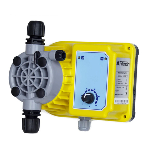
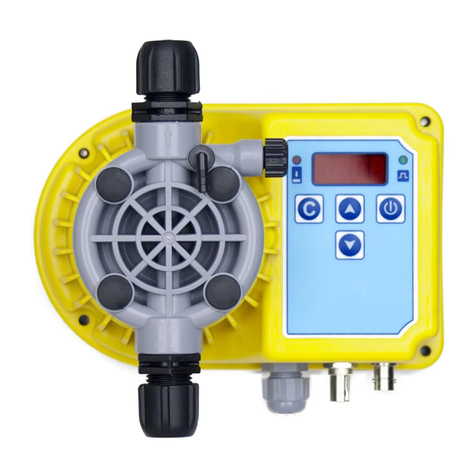
Antech CLS Series User manual


www.antech.com.tr

DOSING PUMPS
R3 Sayfa 2/34
Please read the manual through completely before commissioning this equipment.
Do not discard!
Any part which has been subject to misuse is excluded from the warranty!
Table Of Contents
TABLE OF CONTENTS..................................................................................................................................... 2
1. GENERAL USER INFORMATION ................................................................................................................. 3
2. DEFINITION AND FEATURES....................................................................................................................... 5
2.1. Definition............................................................................................................................................... 5
2.2. General Features .................................................................................................................................. 5
2.3. Electrical Design................................................................................................................................... 5
2.4. Technical Features ............................................................................................................................... 5
3. INSTALLATION ............................................................................................................................................. 7
3.1. Electrical Connection........................................................................................................................... 7
3.2. Assembly and Installation.................................................................................................................... 9
3.3 Injection Group with Ball and Checkvalve......................................................................................... 15
3.4 Suction Group...................................................................................................................................... 16
3.5. Combined Head Group 1-2-3.............................................................................................................. 17
3.6 Head Group 2....................................................................................................................................... 18
3.7 Head Group 4....................................................................................................................................... 19
3.9 Level Sensor Installation..................................................................................................................... 20
4. USAGE......................................................................................................................................................... 21
4.1 Explanations for Analog Models ........................................................................................................ 21
4.2 Explanations for Digital Models.......................................................................................................... 22
4.3. Leds and Meanings............................................................................................................................. 22
4.4. Parameter Settings in Digital Models................................................................................................ 23
4.5 Details of External Socket................................................................................................................... 27
4.6 Volumetrik Modellerde Sayaç Bağlantısı ........................................................................................... 27
4.7 Password Usage.................................................................................................................................. 28
5. SERVICE...................................................................................................................................................... 28
5.1. Maintenance........................................................................................................................................ 28
6. SERVICE...................................................................................................................................................... 29
6.1 Mechanical Failures............................................................................................................................. 29
6.2 Electrical Failures................................................................................................................................ 29
7. CHEMICAL RESISTANCE LIST.................................................................................................................. 31
8. FEED RATE SETTINGS GRAPHS .............................................................................................................. 32
9. MODEL LIST................................................................................................................................................ 33
10. GUARANTEE............................................................................................................................................. 33
10.1. Guarantee.......................................................................................................................................... 33
11. STANDARDS............................................................................................................................................. 33

DOSING PUMPS
R3 Sayfa 3/34
1. General User Information
Please read the following information carefully and complete. This information enables to the highest
benefit to instructions for use.
WARNING
This symbol used for specify the potential risk situations. Ignoring safety
information can endanger life or result in serious injury!
CAUTION
This symbol used for specify the dangerous situations. Ignoring safety information
can result in injury to persons or damage to machinery or other materials!
IMPORTANT
This symbol used for specify the danger situations. Ignoring safety information can
result in damage to machinery or other materials!
SAFETY GUIDELINES
WARNING
The use of toxic or hazardous materials!
This guide has all instructions for lessen the risks of mixing toxic and
hazardous materials always read chemical safety data!
Analyze the hydraulic parts of the dosing pump and use it's just all parts
smooth case.
Use available materials for pipes, records, covers, suction and injection valves.
Please read the notes below 1,2 and 3 for remove the dosing pump. For taking
pressure and draw out the chemicals from the pump head look at "MAINTENANCE"
CAUTION
Before any service :
1. Disconnect pump from electricity,
2. Release the pressured part from pump head and injection line,
3. Discharge dosing liquid from pump head.

DOSING PUMPS
R3 Sayfa 4/34
GENERAL ADVICES
WARNING
Before working on the metering pump, always de-pressurise the discharge line,
empty the liquid end and rinse out!
Never allow the metering pump to operate when the stop valve on the discharge
line is closed, as this can result in the rupture of the discharge line!
CAUTION
Install pump at a dry place far from heat sources and ambient temperature
must be below 40ºC
Make electrical connection in electrical rules (3.1).
Mount pump as in figure 16 Liquid distances at underside and upper side of
pump must be shorter then two meters. Keep pump upper then liquid level ant
close tank tightly.
NOTE
Be cafeful to avoid folding on the pipes
IMPORTANT
Do not remove the screw caps that on the pump head.

DOSING PUMPS
R3 Sayfa 5/34
2. Definition and Features
2.1. Definition
Dosing pumps are sensitive dosing equipments, designed to use in areas (as pools, tap water, agricultural)
that chemicals (like acid, chlorine or liquid fertilizer) must give by dosing.
2.2. General Features
This manual may used for all dosing pumps. Installation, usage and service off all pumps are similar, but
there are some differences at usage, technical information and maintenance.
2.3. Electrical Design
Device makes dosing function as considering to user settings.
The device complies with the following standards:
TS EN 61000–6–1
TS EN 61000–6–3
IEC 60335–2–41
IEC 60335–1
EN 60332–41
EN 60335–1
2.4. Technical Features
2.4.1 Dosing Pump Technical Features
Power Supply
AC 230V 50-60Hz
DC 12V *
Suction Line Max.Height
1,5mt
Injection Line Max.Height
4 mt
Body
IP54
IP65
Ambient Temp.
0–50°C
Chemical Temp.
0–45°C
Weight
CLS Series
2,3 Kg
LARA Series
2,2 Kg
NANO Series
1,7 Kg
2.4.2 Raw Metarials
Parts
CLS Series
LARA Series
NANO Series
Records
PP-PVDF**
Pump Body
ABS
PP
Çekvalfler **
Suction Group
EPDM, Viton, Silicon, Neoprene, Zirconium Ball
Injection Group
EPDM, Viton, Silicon, Neoprene, Zirconium Ball
Head Group
Zirconium Ball
Diaphgram
PTFE
Pump Head
PP-PVDF**
O-Rings
VİTON
Suction Pipe
PVC
Injection Pipe
PE
Discharge Line Pipe
PVC
*In 12 V models / ** May change in models

DOSING PUMPS
R3 Sayfa 6/34
2.4.3 Dimensions
CLS SERIES DOSING PUMPS
Figure 1
Dimensions
A 219mm
B 107.5mm
C 157mm
LARA SERIES DOSING PUMPS
Figure 2
Dimensions
A 185mm
B 107.5mm
C 156mm
NANO SERIES DOSING PUMPS
Figure 3
Dimensions
A 115mm
B 120mm
C 101mm
D 173mm

DOSING PUMPS
R3 Sayfa 7/34
3. Installation
SAFETY INFORMATION
WARNING
The device shouldn’t be damp or wet. Not used open area without any
protection (external box, cover protect from sun and rain.. etc.)
CAUTION
Implement all general safety precautions for installation!
Read this user guide completely and carefully before installation
All electrical connections are just made by specially trained and qualified
persons.
Power supply source value must be same with instruction label on the pump
CAUTION
Choose the electrical connection point far away from the liquids and chemicals
3.1. Electrical Connection
WARNING
Do not connect the electric source before assembly the pump.
Pompa sökülmeden önce elektrik bağlantısı çıkartılmalıdır.
Cut-off all electrical connections before remove the pump
Choose healty ground lined electrical outlet for connect the pumps that needs
ground line
WARNING
Keep the cover closed absolutely when the pump runs
3.1.1 Electrical Connection for DC Models
Figure 4
12V DC Dosing pumps electrical
connection diagram is shown in the
figure at left side
Brown cable connect to the
power supply +(positive) pole and
blue cable connect to –(negative)
pole
Use minimum 1,5mm2 cable for
extend the dosing pump cable

DOSING PUMPS
R3 Sayfa 8/34
3.1.2 Electrical Connection for AC Models
Figure 5
Figure 5 show the CLS models electric connection diagram.
If the CLS series dosing pumps electric cable attached into a safety box protected electric plug please
control the electric line earth contact
Should be use minimum 0,75mm2cable for any addition for extend the electric cable.
Figure 6
LARA and NANO series Dosing pumps electrical connection diagram is shown in the figure at above.
Should be use safety box protected electric plug for connect the dosing pump.
Should be use minimum 0,75mm2cable for any addition for extend the electric cable.

DOSING PUMPS
R3 Sayfa 9/34
3.2. Assembly and Installation
3.2.1 General Installation
Figure 7
The Shape of the device general installation
The Shape of the device general installation should be done like at the above figure.
The suction line should be as short as possible. Distance of the pipe should be max 1,5mt between pump
and suction group.
The suction line should be laid on an ascending incline, to avoid air bubbles collecting.
Device installation should be finished before make the electrical connection.
Electrical connection point should be choosing far away from liquids and chemicals.
Easy readable and usable place should be selected for user’s accsess.
Should be select the mounting are dry and goog ventiled for the device works properly and long-lived.
Numbered 5 flat line show the 230V AC power supply connection, numbered 6 dashed line show the 12V
DC power supply connection.
1 ) Injection Line
2 ) Injection Line Pipe
3 ) Safety Fuse
4 ) DC Power Supply
5 ) AC Power Supply Cable
6 ) DC Power Supply Cable
7 ) Discharge Pipe
8 ) Suction Line Pipe
9 ) Liquid Level Sensor
10) Suction Line

DOSING PUMPS
R3 Sayfa 10/34
3.2.2 Mounting on Wall
Figure 8
For installation use the hole-template that compatible with your pump model. (Figure: 12–13–14–15).
Mark the mounting the device surface according to the listed dimensions.
Drill max.7mm hole for insert the 8mm rawplugs
Fixed the pump with screws after assemble the rawpulgs.
3.2.3 Mounting on Plastic Panel
Figure 9
Screw Size Dimensions
CLS
Series
4 Pieces 5x20
YHB Screw
NANO
Series
2 Pieces 4,2x25
YSB Screw
LARA
Series
4 Pieces 4,2x25
YSB Screw

DOSING PUMPS
R3 Sayfa 11/34
3.2.4 Mounting Holes of the Pumps
The below figures does shown the mounting hole templates for the pumps.
Mark the mounting the device surface according to the listed dimensions before installation
Please make sure that the pump will be installed a clean and dry surface.
CLS SERIES DOSING PUMPS
Figure 10
Dimensions
A 35mm
B 149mm
C 11mm
D Ø6mm
LARA SERIES DOSING PUMPS
Figure 11
Dimensions
A 76mm
B 23mm
C Ø5mm
D 155mm
E 9mm
F 104mm

DOSING PUMPS
R3 Sayfa 12/34
NANO SERIES DOSING PUMPS
Figure 12
Dimensions
A 6mm
B 21,5mm
C 60mm
D Ø5mm
3.2.5 Pump Mounting Position
Figure 13
Figure 14
Right
Wrong
NOTE
Suction and discharge valves (bleed valves for self-degassing liquid ends) must be
in a vertical position. (± 45º )

DOSING PUMPS
R3 Sayfa 13/34
3.2.6 Connecting Tubing
Figure 15
Figure 16
1. When installing suction discharge and bypass lines, ensure they are free from all mechanical stress!
2. Arrange the lines so that it is possible, if necessary, to pull the liquid end and the pump apart sideways!
3. Ensure tubing length ends are cut straight across.
4. Insert tubing through union nut and clamping ring.
5. Push tubing ends up to the stop on the tube nozzle.
6. Place tubing and nozzle onto valve.
7. Tighten union nut, pushing tubing down at the same time.
8. Pull briefly on the tubing attached to the liquid end and then retighten the union nut

DOSING PUMPS
R3 Sayfa 14/34
3.2.7 Discharge Pump
Figure 17
Before working on the metering pump, always de-pressurise the discharge line
Install PVC pipe to the discharge line and after assembly.
Unscrewed the discharge record
Run the dosing pump
Wait until the chemical goes to the tank from the discharge pipe without air bubbles.
Screwed the disharge recorg tightly.
Figure 18
Follow the instroductions that the figure above for the without discharge line pumps
Please run the pump before install the injection group to the line.
Wait until the chemical goes to the injection pipe without air bubbles.
Stop the pump
Install the injection group to the line

DOSING PUMPS
R3 Sayfa 15/34
3.3 Injection Group with Ball and Checkvalve
NOTE
Injection valve group must be fitted up side of the pump head that shown the
arrow sign ( )
All parts of the injection group must be fitted same way and placement that
the figure below
If it changes your pump doesn't work smoothly.
Injection Line With
Checkvalve
Figure 19
Injection Line
With Ball
Figure 20
Çekvalfli Basma Hattı
No
Açıklama
Adet
1
Injection Checkvalve Body
1
2
Checkvalce Rubber Washer
1
3
Checkvalce Rubber
1
4
Checkvalce Rubber Stopper 2
1
5
Record 2 4x6
1
6
Conical pipe entrance 4x6
1
7
Record Cap 2
1
Bilyeli Basma Hattı
No
Açıklama
Adet
1
Injection Checkvalve Body
1
2
Bilye Yuvası 3 Basma Hattı
2
3
Ball 6,35mm
1
4
Bow for Ball Housing
1
5
Record 2 4x6
1
6
Conical pipe entrance 4x6
1
7
Record Cap 2
1

DOSING PUMPS
R3 Sayfa 16/34
3.4 Suction Group
Suction valve group must be fitted bottom side of the pump head that and
immersed the chemical tank.
All parts of the suction group must be fitted same way and placement that the
figure below
If it changes your pump doesn't work smoothly.
Figure 21
No
Açıklama
Adet
1
Suction Checkvalve Body
1
2
Checkvalce Rubber Stopper 2
1
3
Checkvalce Rubber
1
4
Checkvalce Rubber Washer
1
5
Record 2 4x6
1
6
Conical pipe entrance 4x6
1
7
Record Cap 2
1
8
Suction Checkvalve Middle Part
1

DOSING PUMPS
R3 Sayfa 17/34
3.5. Combined Head Group 1-2-3
All parts of the combined head group must be fitted same way and placement
that the figure below
If it changes your pump doesn't work smoothly.
Figure 22
No
Açıklama
Adet
No
Açıklama
Adet
1
Record 2 4x6
2
10
Ball 6.35mm
4
2
Record Cap 2
2
11
Oring 7x1,57
4
3
Discharge Record
1
12
Oring 12x1,2
1
4
Conical pipe entrance 4x6
2
13
Discharge Pipe Input
1
5
Oring 4,5x1,78
5
14
Combined Head Group 1-2-3
1
6
Ball Housing Body-6
1
15
Ball Housing Body-6 (injection)
1
7
Ball Haousing Body-6 Down Cap
2
16
Oring 2,5x1,78
1
8
Ball Haousing Body-6 Up Cap
2
17
Oring 5x1,2
1
9
Ball Haousing Body-6 rove
4
18
Security Stopper Cap 2 4x6
2

DOSING PUMPS
R3 Sayfa 18/34
3.6 Head Group 2
All parts of the head group 2 must be fitted same way and placement that the
figure below
If it changes your pump doesn't work smoothly.
Figure 23
No
Açıklama
Adet
1
Pump Head Group 2
1
2
Record 2 4x6
2
3
Record Cap 2
2
4
Conical pipe entrance 4x6
2
5
Security Stopper Cap 2 4x6
2
6
Ball Hausing 1
4
7
Ball 5mm
4
8
Checkvalve Stopper B
2
9
Checkvalve Stopper A
2

DOSING PUMPS
R3 Sayfa 19/34
3.7 Head Group 4
All parts of the head group4 must be fitted same way and placement that the
figure below
If it changes your pump doesn't work smoothly.
Figure 24
No
Açıklama
Adet
1
Pump Head Group 4
1
2
Record 2 4x6
2
3
Record Cap 2
2
4
Security Stopper Cap 2 4x6
2
5
Conical pipe entrance 4x6
2
6
Ball Hausing 1
4
7
Ball 5mm
4
8
Checkvalve Stopper B
2
9
Checkvalve Stopper A
2
10
Discharge Record
1
11
Oring 6x1,5
1
12
Oring 3x1,5
1
This manual suits for next models
2
Table of contents
Other Antech Water Pump manuals
Popular Water Pump manuals by other brands

ABB
ABB PSTX30 Applications manual

Thetford
Thetford Sani-Con Turbo 700 owner's manual

KABI
KABI KF700-C1 operating manual

GORMAN-RUPP
GORMAN-RUPP AMT 370F-95 Specifications information and repair parts manual

MasterCraft
MasterCraft 062-3425-4 instruction manual

ProMinent
ProMinent DULCO flex Control - DFXa quick start guide