Anthos A7 Plus User manual

ITALIANO
97050825
Rev. 03
2017.03
A7 Plus
EN

A7 Plus –OPERATOR'S MANUAL
2
EN
Contents
1. GENERAL WARNINGS................................................................................................................................................................................... 4
1.1. SYMBOLS...................................................................................................................................................................................................4
1.2. INTENDED USE .........................................................................................................................................................................................5
1.2.1. CLASSIFICATION AND REFERENCE STANDARDS ........................................................................................................................5
1.2.2. ENVIRONMENTAL CONDITIONS......................................................................................................................................................5
1.2.2.1. TRANSPORT AND PACKAGING CONDITIONS................................................................................................................................5
1.2.3. WARRANTY.......................................................................................................................................................................................5
1.2.4. DISPOSING THE EQUIPMENT WHEN NO LONGER USED.............................................................................................................6
1.3. SAFETY WARNINGS..................................................................................................................................................................................6
1.4. CLEANING AND DISINFECTION................................................................................................................................................................8
2. DESCRIPTION OF THE EQUIPMENT............................................................................................................................................................. 9
2.1. IDENTIFICATION PLATES.........................................................................................................................................................................9
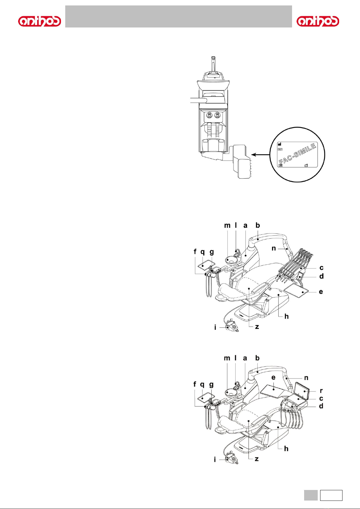
2.2. DENTAL UNITS..........................................................................................................................................................................................9
2.3. DENTAL CHAIR........................................................................................................................................................................................10
3. TURNING ON THE OPERATING UNIT ......................................................................................................................................................... 10
4. DENTAL CHAIR OPERATION ...................................................................................................................................................................... 10
4.1. SAFETY DEVICES....................................................................................................................................................................................11
4.2. EMERGENCY DEVICES...........................................................................................................................................................................11
4.3. ADJUSTABLE HEADREST.......................................................................................................................................................................12
4.4. MOVABLE ARMRESTS (OPTIONAL).......................................................................................................................................................12
5. DENTIST'S BOARD OPERATION................................................................................................................................................................. 13
5.1. DENTIST’S CONTROL CONSOLE ...........................................................................................................................................................16
5.1.1. USER'S INTERFACE.......................................................................................................................................................................18
5.1.1.1. OPERATOR SELECTION................................................................................................................................................................19
5.1.1.2. MAIN SETTINGS .............................................................................................................................................................................19
5.1.1.2.1. BIOSTER DISINFECTION CYCLE SETTING .......................................................................................................................20
5.1.1.2.2. SETTING THE FLUSCHING CYCLE....................................................................................................................................21
5.1.1.2.3. W.H.E. SYSTEM TANK EMPTYING.....................................................................................................................................21
5.1.1.2.6. BOWL AUTOMATIC MOVEMENT SETTING........................................................................................................................23
5.1.1.2.7. FOOT CONTROL SETTING.................................................................................................................................................23
5.1.1.2.8. OPERATING LIGHT SETTING.............................................................................................................................................24
5.1.1.2.9. OTHER SETTINGS...............................................................................................................................................................24
5.1.1.2.10. DATA AND TIME ADJUSTMENT..........................................................................................................................................25
5.1.1.2.11. STOPWATCH.......................................................................................................................................................................25
5.1.1.2.12. FAVOURITE BUTTON CUSTOMIZATION............................................................................................................................26
5.1.1.2.13.OPERATOR DATABASE ENTRY.........................................................................................................................................26
5.1.1.2.14. LANGUAGE SELECTION.....................................................................................................................................................27
5.1.1.2.15. USB SETUP .........................................................................................................................................................................27
5.1.1.2.16. IMAGE MANAGEMENT........................................................................................................................................................28
5.1.1.2.16.1. IMAGE MANAGEMENT THROUGH iRYS............................................................................................................................29
5.1.1.2.17. APEX LOCATOR SETTING..................................................................................................................................................31
5.1.2. SETTING THE DENTAL CHAIR "AUTOMATIC RETURN” AND "RINSE POSITION”.......................................................................31
5.1.3. DENTAL CHAIR POSITION PROGRAMMING.................................................................................................................................32
5.1.4. EMERGENCY BUTTON...................................................................................................................................................................32
5.1.5. TOUCH-SCREEN LOCK BUTTON...................................................................................................................................................32
5.2. FOOT CONTROL......................................................................................................................................................................................33
5.2.1. "MULTIFUNCTION” FOOT CONTROL.............................................................................................................................................33
5.2.2. "PUSH-PEDAL” FOOT CONTROL...................................................................................................................................................34
5.2.3. "POWER PEDAL" FOOT CONTROL................................................................................................................................................36
5.2.4. WIRELESS FOOT CONTROL..........................................................................................................................................................38
5.3. SYRINGE..................................................................................................................................................................................................40
5.4. TURBINE..................................................................................................................................................................................................41
5.5.1. RESTORATIVE OPERATING MODE...............................................................................................................................................47
5.5.2. ENDODONTIC OPERATING MODE................................................................................................................................................48
5.5.2.1. ROOT CANAL DRILL CUSTOMIZATION MENU..............................................................................................................................50
5.5.3. IMPLANT OPERATING MODE ........................................................................................................................................................51
5.5.4. REDUCTION RATIO SETTING MENU.............................................................................................................................................52
5.5.5. RECIPROCATING OPERATING MODE ..........................................................................................................................................53
5.6. SCALER....................................................................................................................................................................................................54
5.7. T LED CURING LIGHT..............................................................................................................................................................................57
5.8. C-U2 DENTAL CAMERA...........................................................................................................................................................................61
5.9. ZEN-Xi INTEGRATED SENSOR...............................................................................................................................................................66
5.10. PERISTALTIC PUMP................................................................................................................................................................................67
5.11. ELECTRONIC APEX LOCATOR...............................................................................................................................................................69

A7 Plus –OPERATOR'S MANUAL
EN
3
6. ASSISTANT’S BOARD OPERATION............................................................................................................................................................ 71
6.1. ASSISTANT’S BOARD CONSOLE ...........................................................................................................................................................71
6.2. SYRINGE..................................................................................................................................................................................................72
6.3. T LED CURING LIGHT..............................................................................................................................................................................72
6.4. C-U2 DENTAL CAMERA...........................................................................................................................................................................72
6.5. SUCTION TUBES.....................................................................................................................................................................................73
6.6. TRAY HOLDER.........................................................................................................................................................................................74
6.7. SALIVA HYDRAULIC SUCTION UNIT......................................................................................................................................................74
7. WATER UNIT OPERATION........................................................................................................................................................................... 75
7.1. FILL CUP AND BOWL ..............................................................................................................................................................................75
7.2. S.H.S. SYSTEM........................................................................................................................................................................................76
7.3. W.H.E. SYSTEM (WATER HYGIENIZATION EQUIPMENT).....................................................................................................................77
7.4. BIOSTER DISINFECTION AUTOMATIC SYSTEM ...................................................................................................................................79
7.5. AUTOMATIC INSTRUMENT FLUSHING CYCLE......................................................................................................................................81
7.6. A.C.V.S. SYSTEM (AUTOMATIC CLEANING VACUUM SYSTEM)..........................................................................................................82
7.7. OPENING/CLOSING THE WATER UNIT SIDE COVER...........................................................................................................................83
8. ACCESSORIES............................................................................................................................................................................................. 84
8.1. OPERATING LAMP ..................................................................................................................................................................................84
8.2. MONITOR ON LAMP POLE......................................................................................................................................................................84
8.3. NEGATOSCOPE FOR PANORAMIC X-RAYS..........................................................................................................................................84
8.4. AIR/WATER/230V QUICK-COUPLINGS...................................................................................................................................................85
8.5. AUXILIARY TRAY HOLDER .....................................................................................................................................................................85
9. MAINTENANCE............................................................................................................................................................................................. 86
9.1. MAINTAINING THE INSTRUMENTS........................................................................................................................................................86
9.2. DRAINING CONDENSATE.......................................................................................................................................................................86
9.3. CLEANING THE SURGICAL SUCTION FILTER.......................................................................................................................................87
9.4. SURGICAL SUCTION...............................................................................................................................................................................87
9.5. CATTANI SURGICAL SEPARATOR.........................................................................................................................................................88
9.6. CLEANING THE TURBINE RETURN AIR FILTER....................................................................................................................................89
9.7. CATTANI GRAVITY SURGICAL SEPARATOR.........................................................................................................................................89
9.8. METASYS AMALGAM SEPARATOR........................................................................................................................................................90
9.9. DÜRR AMALGAM SEPARATOR..............................................................................................................................................................90
9.10. DENTAL CHAIR........................................................................................................................................................................................90
10. WARNING MESSAGES................................................................................................................................................................................. 91
11. TECHNICAL DATA........................................................................................................................................................................................ 93
11.1. DIMENSIONAL CHARACTERISTICS .......................................................................................................................................................94
12. DENTAL UNIT OPERATING UNIT MAINTENANCE PLAN........................................................................................................................... 96

A7 Plus –OPERATOR'S MANUAL
4
EN
1. GENERAL WARNINGS
•These instructions explain how to correctly use the following dental units:
A7 Plus CONTINENTAL
A7 Plus INTERNATIONAL
Please carefully read this manual before using the device.
•The dental units described in this manual are manufactured by CEFLA s.c. - via Selice Prov.le 23/A - 40026 Imola (BO) Italy, a manufacturer
complying with the European Directive on devices.
•These instructions describe all the versions of the dental units with the maximum possible accessories, therefore not all the paragraphs are applicable
to the unit you have purchased.
•It is forbidden to reproduce, store and transmit this publication by any means (electronically, mechanically, by photocopying, translating or in other
ways) without a written authorisation issued by CEFLA s.c..
•The information, technical specifications and illustrations contained in this publication are not binding.
CEFLA s.c. reserves the right to introduce modifications and technical improvements without having to modify these instructions.
•The manufacturer has a company policy of continual development. Although every effort is made to keep technical documentation up-to-date at all
times some of the instructions, specifications and figures given in this manual may slightly differ from the purchased product. The manufacturer
reserves the right to make changes without prior notice.
•The original text is in Italian; translation from the original in Italian.
•This equipment is equipped with a device that prevents liquid back flow.
•The manufacturer’s website contains a list of authorised agents of the various countries.
1.1. SYMBOLS
Note the meaning of the following symbols and expressions:
Type of protection against direct and indirect contact:
Class I.
Type of protection against direct and indirect contact:
Type B.
Equipment in compliance with essential requirements of
directive 93/42/EU and subsequent changes
( Class IIa Medical Device).
Notified body: IMQ spa.
WARNING!
Failure to observe may result in equipment damage or
injury to the user and/or patient.
Accessory in compliance with essential requirements of
directive 93/42/EU and subsequent changes
( Class I Medical Device).
"Consult the instruction manual"
It means that it is advisable to consult the instruction
manual before using that part of the device.
Disposal symbol in accordance with Directive
2012/19/EU
NOTE:
Identifies information that is especially important for the
user and/or the assistant.
“Warning biological hazard”.
It provides information about possible risks of
contamination deriving from contact with fluids, storage of
infected biological waste.
Protective ground contact.
Manufacturer.
Alternating current.
Month and year of construction.
Part that can be sterilised in a steam autoclave up to 135°
C.
Device serial number.
ON / OFF button.
DVGW mark (Quality assurance kitemark regarding
supply of drinking water).
"Refer to the instruction manual"
Means that for reasons of safety you need to consult the
instruction manual before using the equipment.
Product/equipment identification code.
Off (a part of the unit).
Pushing prohibited.
On (a part of the unit).
Foot crushing hazard.
Equipment On.
Equipment equivalent to Class 2 light source.
Equipment OFF.
Hand crushing hazard.
Ukrainian national symbol of conformity.

A7 Plus –OPERATOR'S MANUAL
EN
5
1.2. INTENDED USE
•The dental units described in this manual are Medical Devices intended for dental treatment.
•The dentist's board may hold up to 6 instruments.
•The assistant’s board can hold 2 suction tubes and 3 instruments.
•This equipment must be used only by adequately trained personnel (dentists and paramedics).
•The device is intended for non-continuous operation with intermittent loads (see the operating times of the individual parts in the dedicated sections).
•The device is classified as pollution degree 2.
•Overvoltage class: II.
1.2.1. CLASSIFICATION AND REFERENCE STANDARDS
•MEDICAL DEVICES classification
Classification of the dental unit in accordance with the indications given in annex IX of directive 93/42/EC as amended:
Class IIa.
•ELECTRICAL MEDICAL EQUIPMENT classification
Classification of the dental unit in accordance with standard EN 60601-1 on safety of medical equipment: Class I - Type B.
•Reference standards: the dental units described in this manual are designed and manufactured in compliance with IEC60601-1 3rd Ed. - 2007, IEC
60601-1-6 3rd Ed. - 2010, IEC 62366 1st Ed. - 2007, IEC 80601-2-60 1st Ed. - 2012, IEC 60601-1-2 3rd Ed., ISO 6875 3rd Ed. - 2011, ISO 7494-1
2nd Ed. - 2011 and EN 1717 (type AA and AB) standards as far as water mains safety devices are concerned.
•Classification of RADIO DEVICES AND COMMUNICATION TERMINALS (only when the WIRELESS foot control is present)
Equipment classification according to Directive 99/05/EC Art.12: Class I.
1.2.2. ENVIRONMENTAL CONDITIONS
The equipment is to be installed in rooms that satisfy the following requirements:
•temperature between 10 and 40 °C;
•relative humidity between 30 and 75%;
•atmospheric pressure ranging from 700 to 1060 hPa;
•altitude ≤ 3000 m;
•air pressure entering equipment ranging from 6 to 8 bar;
•water hardness at the equipment inlet must not be above 25 °f (French degrees) or 14 °d (German degrees) for untreated drinking water. For water
with a higher hardness degree, it is recommended to soften water until it reaches a hardness degree between 15 and 25 °f (French degrees) or
between 8.4 and 14 °d (German degrees);
•water pressure entering equipment ranging from 3 to 5 bar;
•water temperature entering equipment not higher than 25 °C.
1.2.2.1. TRANSPORT AND PACKAGING CONDITIONS
•Temperature between -10 and 70°C;
•Relative humidity between 10 and 90%;
• Atmospheric pressure: from 500 to 1060hPa.
1.2.3. WARRANTY
CEFLA s.c. stands behind its products warranting safety, reliability and performance.
The warranty is valid only under the following terms:
•Conditions given on the warranty certificate are observed.
•Yearly scheduled maintenance is performed.
•The equipment is used only as instructed in this manual.
•The electrical wiring in the room in which the equipment is installed must conform to IEC 60364-7-710 (standards for electrical wiring in medical and
dental offices).
•A 3x1.5 mm2line protected by a bi-polar cut-out that conforms to applicable standards (10 A, 250 V, distance between contacts at least 3 mm) must be
used to feed the equipment.
WARNING:
The colour of the three wires (POWER, NEUTRAL and EARTH) should satisfy the requirements of current standards.
•Installation, repairs and, in general, any other operation requiring the casing to be opened are to be performed exclusively by personnel authorised by
ANTHOS.

A7 Plus –OPERATOR'S MANUAL
6
EN
1.2.4. DISPOSING THE EQUIPMENT WHEN NO LONGER USED
In compliance with Directives 2011/65/EU and 2012/19/EU regarding restriction of the use of certain hazardous substances in electrical and electronic
equipment along with waste electrical and electronic equipment, it is forbidden to dispose of this equipment in the municipal waste stream as unsorted
municipal waste.
When new equipment that is similar is purchased, the old equipment must be given to the dealer for disposal. As regards reuse, recycling and other
forms of recovery of waste electrical and electronic equipment, the manufacturer carries out the functions defined by current local laws. A high level of
separate collection of waste electrical and electronic equipment is indispensable to efficiently recycle, treat and dispose of the equipment. Recycling and
treatment operations should comply with minimum standards to assure human health and high environmental protection as well as favour recycling of
the materials included in the equipment. The symbol indicating separate collection for electrical and electronic equipment
consists of the crossed out bin marked on the equipment.
WARNING:
Illegal waste clearance and disposal shall be punished as established by laws and regulations currently in force in the individual
countries.
1.3. SAFETY WARNINGS
WARNING:
•All devices are permanently installed.
Depending on the type of dental chair the unit comes with, refer to the installation SCHEMATICS in paragraph "Technical Specifications”.
The CEFLA s.c. shall not be held liable for any personal injury or property damage arising from failure to heed the following clause.
•Floor conditions.
The floor (continuous) should meet the load-bearing capacity set forth by DIN 1055, sheet 3.
The weight of the dental unit including a 190 kg patient is about 350 kg.
For further details on anchoring conditions, refer to the Installation Manual.
The positions of delivery and drain line connections comply with standard UNI EN ISO 11144.
In case of floor installation without load reduction plate, floor characteristics must ensure a breaking strength of the anchor bolt not less than 1200 daN
each (considering RcK concrete strength 20 MPa).
In case of floor installation without load reduction plate, floor characteristics must ensure a strength of the anchor bolt not less than 260 daN.
•This device may not be modified in any way without the authorisation of the manufacturer.
If the device is modified, appropriate examinations and tests need to be conducted in order to ensure continued safe use.
CEFLA s.c. shall not be held liable for any personal injury or property damage arising from failure to heed the following clause.
•Dental chair.
Dental chair maximum loading capacity is 190 Kg. Do not exceed this value.
•Tray holder bearing surface.
The maximum loading capacity must never be exceeded:
- tray holder module attached to the dentist's board, maximum allowable load 2 Kg, evenly distributed.
- tray holder module attached to the assistant's board, maximum allowable load 1 Kg, evenly distributed.
- auxiliary tray holder module, maximum allowable load on tray 3.5 Kg (without negatoscope) or 2.5 Kg (with negatoscope).
•Connections to external instruments.
The equipment can be hooked up only to other instruments that bear the CE mark.
•Electromagnetic interferences.
Use of electrical equipment that does not comply with standard IEC 60601-1 3rd Ed. - 2007 in the office or nearby may cause electromagnetic or other
types of interferences resulting in dental unit malfunctions.
In these cases it is recommended to shut off the dental unit power before using this equipment.
•Replacing the drills.
Operate the turbine release and contra-angle devices only once the drill has come to a complete stop. Failure to do so, will result in damaging the
locking system and drills could be released and cause injury. Exclusively use high-quality drills with a connection having a calibrated diameter. To
check the conditions of the locking system, make sure the drill is firmly secured to the instrument every day before starting work. Locking system
defects caused by misuse can be easily identified and are not covered by the warranty.
The drills and various instruments attached to the handpieces must comply with Biocompatibility Standard ISO 10993.
•Patients with pace makers and/or hearing aids.
When treating patients with pace makers and/or hearing aids, take into consideration the effects the instruments may have on pace makers and/or
hearing aids. Carefully read technical-scientific information available on this subject.
•Implants.
If the dental unit is used for implant operations using separate equipment designed for this purpose, you are recommended to shut the power off the
dental chair to avoid unwanted movements resulting from faults and/or accidental start-ups of the controls.
•Do not forget to turn off the office water supply and master switch of the equipment before leaving the surgery.
•The equipment is not protected against liquid penetration (IPX 0).
•The equipment is not suitable for use in the presence of a mixture of flammable anaesthetic gas with oxygen or nitrous oxide.
•This equipment must be stored properly so that it is kept in top working order at all times. The manufacturer shall not be held liable for misuse,
carelessness or improper use of the equipment.
•The equipment may only be used by authorised and adequately trained staff (dentists and paramedics).
•The user must be present at all times when the equipment is turned on or ready for start-up. In particular, never leave the equipment unattended in the
presence of children/ mentally disabled or other unauthorised personnel in general.
Any accompanying persons must keep out of the operating area and in any case under the responsibility of the operator. The operating area refers to
the space around the dental unit plus 1.5 meters.

A7 Plus –OPERATOR'S MANUAL
EN
7
•Quality of the water delivered by the dental unit.
The user is responsible for the quality of the water delivered by the dental unit and must adopt measures to maintain the water quality.
To ensure that delivered water is kept to quality standards, CEFLA s.c. recommends equipping the dental unit with an internal or external disinfection
system.
The dental unit, once installed, is exposed to possible contaminants coming from the water mains. So, to effectively overcome this problem, it is
advisable to install the dental unit only when its use will be daily and to perform the disinfecting procedures starting from the day in which it is installed
by following the instructions set forth in the relevant sections.
If the dental unit is equipped with the air separation device from water mains (EN 1717), make sure that the expected continuous supply of disinfectant
is also carried out by ensuring that the relevant tank contains a suitable quantity of disinfectant (see relevant paragraph).
NOTE:
contact your local dealer or Dentists Association for more detailed information about national laws and requirements.
•Applied parts.
The parts of the equipment that come into contact with the patient while carrying out its functions correctly during standard use are: dental chair
upholstery, armrest, curing light fibre optics, syringe terminal, disposable camera protection, scaler bits, handpiece drills, suction tube terminals.
Non applied parts that may come into contact with the patient are: dental chair armrest support, dental chair lower casing, patient-side water unit
casing, water-to cup-spout, bowl, suction tubes, handpiece body.
WARNING:
Dental chair movement.
Make sure that the patient is ready to collaborate: ask
him/her to keep his/her hands and feet close to the body,
avoiding incorrect postures.
Check that the patient is sitting properly when moving the
dental chair (see figure).

A7 Plus –OPERATOR'S MANUAL
8
EN
1.4. CLEANING AND DISINFECTION
Cleaning is the first step of any disinfecting process.
Physically scrubbing with detergents and surface-active substances and rinsing with water removes a considerable amount of micro-organisms. If a
surface is not clean first, the disinfecting process cannot be successful.
If a surface cannot be adequately cleaned, it should be protected with barriers.
The outer parts of the equipment must be cleaned and disinfected using a product for hospital use with indications for HIV, HBV and tubercolocide
(medium-level disinfectant) specifically for small surfaces.
The various drugs and chemical products used in dental surgeries may damage the painted surfaces and the plastic parts. Researches and tests
performed show that the surfaces cannot be fully protected against the harsh action of all products available on the market. We therefore recommend
protecting with barriers whenever possible.
The harsh actions of chemical products also depend on the amount of time they are left on the surfaces.
It is therefore important not to leave the product on the surfaces longer than the time specified by the manufacturer.
It is recommended to use the specific medium-level disinfectant, STER 1 PLUS (CEFLA s.c.), which is compatible with:
•Coated surfaces and plastic parts.
•Upholstery.
WARNING:
The MEMORY FOAM upholstery will stain when splashed with mordant acid. Immediately rinse with plenty of water if acid splatters
on the upholstery.
•Uncoated metal surfaces.
If you do not use STER 1 PLUS, it is recommended to use products that contain at maximum:
•Ethanol. Concentration: maximum 30 g per 100 g of disinfectant.
•1-Propanol (n-propanol, propyl alcohol, n-propyl alcohol). Concentration: maximum 20 g per 100 g of disinfectant.
•Combination of ethanol and propanol. Concentration: the combination of the two should be maximum 40 g per 100 g of disinfectant.
WARNING:
•Do not use products containing isopropyl alcohol (2-propanol, iso-propanol).
•Do not use products that contain sodium hypochlorite (bleach).
•Do not use cleaners that contain phenols.
•Do not spray the selected products directly on the surfaces.
•All products must be used as directed by the manufacturer.
•Do not mix the STER 1 PLUS disinfectant with other products.
WARNING:
The products suggested are compatible with the materials of the equipment, however damages may occur to surfaces and
materials resulting from the use of different products, even if not included in the above list of excluded products.
Cleaning and disinfecting instructions.
Clean and disinfect with disposable non-abrasive paper (avoid using recycled paper) or sterile gauze.
Do not use sponges or, in any case, any material that can be reused.
WARNING:
•Turn off the dental unit prior to cleaning and disinfecting the external parts.
•All materials used to clean and disinfect must be thrown away.

A7 Plus –OPERATOR'S MANUAL
EN
9
2. DESCRIPTION OF THE EQUIPMENT
2.1. IDENTIFICATION PLATES
The plate is found on the arm between the dental chair and water unit.
Data given on plate:
•Manufacturer’s name.
•Name of equipment.
•Rated voltage.
•Type of current.
•Nominal frequency.
•Maximum absorbed power.
•Serial number.
•Month and year of manufacture.
2.2. DENTAL UNITS
Models:
A7 PLUS CONTINENTAL version.
CONTINENTAL version dentist's board (instruments will return to their
original positions through the pulling action of the spring-operated arms)
attached to a double supporting arm, one of which is articulated and self-
balancing.
Description of the different parts:
aWater unit.
bAdjustable arm.
cDentist's board.
dDentist’s control console.
eTray holder board.
fAssistant’s board.
gAssistant’s board control console.
hConnection box.
iMultifunction foot control.
lWater-to-cup spout.
mBowl.
nSelf-balancing arm.
qTray holder board on assistant's board (optional).
zANTHOS A2.7 dental chair.
A7 Plus INTERNATIONAL version.
INTERNATIONAL version dentist's board (instruments placed vertically
in appropriate seats) attached to a double supporting arm, one of which
is articulated and self-balancing.
Description of the different parts:
aWater unit.
bAdjustable arm.
cDentist's board.
dDentist’s control console.
eTray holder ( optional ).
fAssistant’s board.
gAssistant’s board control console.
hConnection box.
iMultifunction foot control.
lWater-to-cup spout.
mBowl.
nSelf-balancing arm.
qTray holder board on assistant's board (optional).
zANTHOS A2.7 dental chair.

A7 Plus –OPERATOR'S MANUAL
10
EN
2.3. DENTAL CHAIR
Description of the parts.
aHeadrest.
bBackrest.
cFixed armrest.
dRight movable armrest ( optional ).
eSafety foot board.
Operating time.
The operating and rest times are as follows:
work 25 sec. - rest 10 min.
Maximum permitted load.
Dental chair maximum loading capacity is 190 Kg.
WARNING:
Do not exceed this value.
Warnings for use
WARNING:
FOOT CRUSHING HAZARD
Pay attention to the patient and the staff during dental
chair descent.
3. TURNING ON THE OPERATING UNIT
Press the main switch ( f1 ) positioned on connection box casing and
check the following on the control console:
•Display ( g ) is off:
- equipment is off
- pneumatic system is disconnected
- water system is disconnected.
•Display ( g ) is on:
- equipment is on
- pneumatic system on
- water system is connected.
WARNING:
Main switch must be pressed with your hands.
4. DENTAL CHAIR OPERATION
The dental chair can be moved as follows:
•Chair seat up/down.
•Backrest up/down with inclination of the chair seat (compensated
Trendelenburg)
The dental chair can be operated from the following units:
•Dentist's board ( a) (see par. 5.).
•Multifunction foot control ( b) (see par. 5.2.).
•Assistant’s board ( c) (see par. 6.).

A7 Plus –OPERATOR'S MANUAL
EN
11
Dental chair movement lock.
With the instruments in rest position, dental chair movements can be
disabled (see paragraph 5.1.1.2.5).
Movement disabling is highlighted on the console display by the special
icon (A).
4.1. SAFETY DEVICES
•The floor board is equipped with a device ( l) that immediately stops
the dental chair from moving down in the presence of an obstacle and
automatically lifts it up to free the obstacle.
•The backrest is equipped with a device ( m) that immediately stops the
backrest from moving down in the presence of an obstacle and
automatically lifts it up to free the obstacle.
•The arms of the assistant’s board are equipped with a safety device ( n
) that immediately stops the dental chair from moving down in the
presence of an obstacle and automatically moves it up to free the
obstacle.
• Dental chair movements:
- with the instrument extracted NOT working: manual movements
allowed, automatic movements inhibited, but if they are already in
progress at the moment of extraction they are not interrupted;
- with instrument extracted and working: all the chair movements are
inhibited.
4.2. EMERGENCY DEVICES
WARNING:
Use the devices below when movement of the equipment needs to
be stopped:
•Dental chair control buttons ( a ) or ( c ).
By pressing any of the dental chair control buttons all movements will
be stopped.
•Foot control ( b ).
When the foot control is activated, all movements of the equipment are
stopped.
•Foot board ( i ).
When the chair foot board is actuated, all movements of the equipment
are blocked.

A7 Plus –OPERATOR'S MANUAL
12
EN
4.3. ADJUSTABLE HEADREST
The headrest may be of two types:
(1) with manual cushion lock lever
(2) with pneumatic cushion lock lever
Adjusting headrest height.
•with manual lock ( 1 ):
The head rest blade is positioned through a magnetic clutch. The
operator should pull up and/or push down the headrest until it is in the
desired position.
•with pneumatic lock ( 2 ):
Press and hold down the locking button ( u) to position the headrest as
desired. Once you have reached the desired position, release the
button ( u) to lock the headrest in place.
Adjusting the cushion.
•with manual lock ( 1 ):
Rotate the lock knob ( k) anti-clockwise, position the cushion as
desired and then re-tighten the lock knob.
•with pneumatic lock ( 2 ):
Press the lock button ( u) and keep it pressed as you adjust the
cushion as desired. Once the cushion is oriented as desired just
release the button ( u) to lock in place.
Proper positioning of the headrest.
WARNING:
For correct use of the headrest, position the patient's head
as shown in the figure.
Warnings for use.
WARNING:
•Maximum permitted load on headrest: 30 Kg.
•Do not attempt to move headrest while patient is resting
against it.
•Do not attempt to modify the position of the cushion
without first releasing the lock mechanism.
•The pneumatic locking device is active only when the air
circuit is pressurized and the dental unit is on.
4.4. MOVABLE ARMRESTS (OPTIONAL)
Movable armrest overturning.
Turn movable armrest downwards so that the patient can easily get on
and off the chair.
Movable armrest removal.
Move the armrest in vertical position and slide it out from seat.
WARNING:
Maximum load supported by armrest: 68 kg.

A7 Plus –OPERATOR'S MANUAL
EN
13
5. DENTIST'S BOARD OPERATION
Layout of instruments.
The positions of the instruments on the board are determined by the
customer at the time of order.
Activation of instruments.
•The syringe is always on (see paragraph 5.3.).
•The curing light is turned on by the relevant button, when the
instrument is extracted (see paragraph 5.7.).
•Intraoral camera turns on when the instrument is extracted (see
paragraph 5.8.).
•ZEN-Xi integrated sensor, if connected to an external PC, is always
active (see paragraph 5.9.).
•Once extracted, all other instruments are operated with the foot control
(see paragraph 5.2.).
Simultaneous use of the instruments.
An interlocking device ensures that the instruments are not used
simultaneously.
The first extracted instrument is ready to be used while those extracted
later are disabled by the interlocking device.
This interlocking device allows the drill to be changed in one instrument
while another is used on the patient.
Positioning the dentist's board.
The dentist's board can move in all directions.
To adjust the height of the board and/or direct it horizontally, simply
grasp the handle ( a).
NOTE CONTINENTAL version:
to release pantograph arm pneumatic brake, grasp the handle
with your thumb on point (A).
NOTE for INTERNATIONAL version:
to adjust height, first press the special release button (see
paragraph 5.1.).
Instrument recall arm locking device (for CONTINENTAL boards,
only).
If this device is provided, the instrument recall arm can be locked in the
instrument extracted position.
Lock engages with a click at about 2/3 of the total arm travel.
To go back to the original condition, simply move the arm to the end of
its travel ( B ).
Tray holder for CONTINENTAL board.
The tray holder ( f) is made of stainless steel and can easily be removed
from its support.
WARNING:
Maximum permitted load on the tray holder ( f ): 2 kg evenly
distributed.

A7 Plus –OPERATOR'S MANUAL
14
EN
Tray holder for INTERNATIONAL board.
WARNING:
Maximum permitted load on the tray holder ( e ): 2 kg
evenly distributed.
Console unit position reversal (with reversible console, only).
WARNING:
Before carrying out this operation, turn the dental unit off.
NEVER REMOVE THE CONSOLE FROM BOARD IF DENTAL
UNIT IS ON.
To reverse console unit position on dentist's board, proceed as follows:
•Remove the console unit after having loosened the relevant fixing ring
nut ( g) by turning it counter clockwise.
•Remove the click-on cap ( s) protecting the quick coupling on the left-
hand side, and insert it inside the one on the right-hand side.
•Turn console unit supporting arm by 180°.
•Fit the console unit inside the quick coupling on left-hand side.
To identify the correct positioning of the console unit, push arm fully
down inside support and, at the same time screw ring nut by approx.
1/3 of a turn until it locks in place, but without forcing it.
NOTE:
to avoid that dentist's board can escape on the other side,
turn it by approx. 90° compared to its supporting arm position
(see figure) before starting its positioning.
•Now dental unit can be turned on again.
WARNING:
During console cleaning operations, do not exert too
much pressure on control pad to avoid putting stress on
to the connection.
USB connector.
Dentist's board is equipped with a "host" USB port, with A type
connector. Port can supply the connected peripheral, up to a max. of 500
mA.
To use USB connector, see paragraphs 5.1.1.2.15 and 5.1.1.2.16.
WARNING:
•Connector is not protected against liquid penetration.
•Do not insert metal objects other than a A type USB
connector inside the connector.
•When unused, we recommend always covering the
connector with the special rubber cap.
Supported devices:
- USB flash drives 2.0 or 3.0 with a storage capacity between 128 MB
and 64 GB,
- USB 2.0 or 3.0 external hard disks, provided that they are separately
powered,
- flash drives or hard disks formatted in FAT and FAT32 formats,
normally available on the market,
- the devices formatted according to the NTFS standard are not
compatible.
NOTE:
port features a current limiter avoiding the console to be
damaged in case of accidental connection of faulty devices.

A7 Plus –OPERATOR'S MANUAL
EN
15
Cleaning the dentist's board.
Clean the dentist's board using a suitable product (see paragraph 1.4).
NOTE for CONTINENTAL version instrument boards:
instrument holder ( x) can be removed to make cleaning
operations easier; to remove it, simply extract it from its seat as
it is fixed with magnets.
The silicone instrument holder ( u) can also be sterilised in an
autoclave up to 135°C.
Removable instrument cords.
All instruments are provided with removable cords to make cleaning
operations easier.
NOTE for CONTINENTAL version instrument boards:
to remove cords, first remove instrument holder, then loosen
the relevant plastic ring nuts.
NOTE for INTERNATIONAL version boards:
to remove cords, simply loosen the relevant plastic ring nuts
positioned under board.
WARNING:
•Before removing instrument cords, turn operating unit
off.
•After having turned operating unit off, drain syringe ducts
by pressing the relevant air and water buttons directly on
bowl until all spray water has flowed out.
•TURBINE, MICROMOTOR and SCALER instrument cords
contain water; it is therefore recommended to remove
cord by keeping the handpiece side end on the bowl.
•When refitting a cord, make sure that electric contacts are
dry and that the plastic ring nut is well tightened.
•Each cord must be refitted only and exclusively inside the
corresponding instrument holder.
Clean the instrument cord using a suitable product (see Paragraph 1.4).
WARNING:
Instrument cords are NOT designed for sterilization in
autoclave or by being cold soaked in solution.

A7 Plus –OPERATOR'S MANUAL
16
EN
5.1. DENTIST’S CONTROL CONSOLE
Dental units A7 are equipped with a dentist's console with touch-screen
interface, consisting of a backlit multi-touch glass capacitive touch panel
and a wide 5.7" colour TFT display, with LED backlighting, 640x480 pixel
resolution and 16.7 million colour imaging.
(1) Control pad for the following models:
A7 CONTINENTAL
(2) Control pad for the following models:
A7 INTERNATIONAL
Description of capacitive buttons:
Touch-screen lock button.
Dentist’s instrument board ascent button (INTERNATIONAL
versions).
Dentist’s instrument board descent button (INTERNATIONAL
versions).
Description of icon buttons displayed on the touch panel:
MAIN SETTINGS menu recall.
Operator change.
Warning icon displaying.
1)
2)
Operating light On/Off.
Assistant's call.
S.H.S. system enabling/disabling
Bowl counter-clockwise movement control
(active with motor-driven bowl, only).
Bowl clockwise movement control
(active with motor-driven bowl, only).
Water-to-cup control.
Water-to-bowl control.
Dental chair function saving.
Emergency position recall.
Reset position recall.
Rinsing position recall.
Seat up and programmed position A recall.
Backrest up and programmed position B recall.
Seat down and programmed position C recall.
Backrest down and programmed position D recall.
NOTE: operation of dental chair buttons.
•Button pressed shortly: automatic recall of set position.
•Button held pressed: manual positioning.

A7 Plus –OPERATOR'S MANUAL
EN
17
Warning icons.
When icon button is touched on the display, warning icons can be
displayed at any time; these icons show dental unit operating status.
Displayed warning icons are:
W.H.E. system working.
Distilled water delivery on.
Mains water delivery on.
Peristaltic pump on with quantity of delivered saline solution
equal to 1.
Peristaltic pump on with quantity of delivered saline solution
equal to 2.
Peristaltic pump on with quantity of delivered saline solution
equal to 3.
Peristaltic pump on with quantity of delivered saline solution
equal to 4.
Peristaltic pump on with quantity of delivered saline solution
equal to 5.
Distilled water tank in reserve.
Duct disinfectant fluid tank in reserve.
BIOSTER cycle in progress.
Suction tube flushing cycle in progress.
Suction disabled because reservoir is full.
Green: wireless foot control battery charged.
Orange: wireless foot control battery 50% charged.
Red: wireless foot control battery flat.
Green: wireless foot control connected and active.
Orange: wireless foot control connected but not active.
Red: searching for wireless foot control connection.
Pantograph arm brake locked.
Light blue: COLD water in cup.
Orange: WARM water in cup.
Red: HOT water in cup.
Automatic dental chair programmed position A.
Automatic dental chair programmed position B.
Automatic dental chair programmed position C.
Automatic dental chair programmed position D.
Dental chair movements locked.
Automatic dental chair programme rinse position.
Automatic dental chair programme reset position.
Automatic dental chair programme emergency position.
Dental chair saving function on.
Dental chair position set manually.

A7 Plus –OPERATOR'S MANUAL
18
EN
5.1.1. USER'S INTERFACE
Upon turning on, the dental unit runs a short self-diagnosis cycle ending
when the main screen with the name of the last set operator appears on
the display.
From now onwards some settings of the operating unit can be edited
through a simple menu system (see next paragraphs).
Navigation controls.
•To access the setting menus, touch icon button .
•To access the different sub-menus, simply touch the relevant icon
button.
•Once menu is accessed, to edit a setting, simply touch the relevant
icon button.
•Once menu is accessed, to edit a settable numerical value, simply
touch icon buttons or .
•To quit a menu, simply touch icon button .
User interface menu.
Settable functions:
•Operator selection (see paragraph 5.1.1.1.).
•General settings (see paragraph 5.1.1.2.).
•BIOSTER disinfection cycle setting (see paragraph 5.1.1.2.1.).
•FLUSHING cycle setting (see paragraph 5.1.1.2.2.).
•W.H.E. tank emptying system (see paragraph 5.1.1.2.3.).
•Water-to-bowl setting (see paragraph 5.1.1.2.4.).
•Water-to-cup setting (see paragraph 5.1.1.2.5.).
•Bowl movement management (see paragraph 5.1.1.2.6.).
•Foot control setting (see paragraph 5.1.1.2.7.).
•Operating light setting (see paragraph 5.1.1.2.8.).
•Other settings (see paragraph 5.1.1.2.9.).
•Time and date setting (see paragraph 5.1.1.2.10.).
•Stopwatch (see paragraph 5.1.1.2.11.).
•Favourite buttons customisation (see paragraph 5.1.1.2.12.).
•Operator database entry (see paragraph 5.1.1.2.13.).
•Language selection (see paragraph 5.1.1.2.14.).
•USB setup (see paragraph 5.1.1.2.15.).
•Image management (see paragraph 5.1.1.2.16.).
•APEX LOCATOR setting (see paragraph 5.1.1.2.17.).
Error messages.
During the starting cycle of self-diagnosis, the dental unit could detect
some malfunctions of internal systems.
Should this be the case, an error message (see paragraph 10) will be
displayed and will disappear only after the operator touches the TOUCH
DISPLAY.
If fault does not represent a hazard, dental unit continues working.
Standby condition.
After approximately 10 minutes of inactivity, the dental unit switches to
the energy-saving status (standby); this status is signalled by the
ANTHOS logo appearing on the console display.
Standard operating conditions will be resumed as soon as any operation
is carried out.

A7 Plus –OPERATOR'S MANUAL
EN
19
5.1.1.1. OPERATOR SELECTION
The console allows managing 4 different operators.
The following data can be set for each single operator:
•Name of operator.
•Turbine and scaler power adjustment.
•3 operating modes for electric micromotor.
•4 operating modes for scaler.
•Turning on and adjustment of the fibre optics of each single instrument.
•Turbine and scaler incremental power control or ON/OFF.
•Dental chair movement automatic programmes.
•Water unit setting parameters.
•Favourite buttons.
•Time set in stopwatch.
Operator selection.
From main screen, touch icon button and then select the desired
operator among the 4 available ones.
5.1.1.2. MAIN SETTINGS
From main screen, touch icon button to access the MAIN
SETTINGS menu including the following icon buttons:
BIOSTER disinfection cycle setting
(if BIOSTER system is installed, only)
(see paragraph 5.1.1.2.1.)
FLUSHING cycle setting
(if I.W.F.C. system is installed, only )
(see paragraph 5.1.1.2.2.)
W.H.E. tank emptying system
(if W.H.E. system is installed, only)
(see paragraph 5.1.1.2.3.)
Water-to-bowl setting
(see paragraph 5.1.1.2.4.)
Water-to-cup setting
(see paragraph 5.1.1.2.5.)
Bowl automatic movement setting
(with motor-driven bowl, only)
(see paragraph 5.1.1.2.6.)
Foot control setting
(see paragraph 5.1.1.2.7.)
Operating light setting
(see paragraph 5.1.1.2.8.)
Other settings
(see paragraph 5.1.1.2.9.)
Time and date setting
(see paragraph 5.1.1.2.10.)
Stopwatch
(see paragraph 5.1.1.2.11.)
Favourite button setting
(see paragraph 5.1.1.2.12.)
Operator database entry
(see paragraph 5.1.1.2.13.)
Language selection
(see paragraph 5.1.1.2.14.)
USB SETUP
(see paragraph 5.1.1.2.15.)
Image management
(see paragraph 5.1.1.2.16.)
Access service menu
(for Technical Service,only)
APEX LOCATOR settings
(if APEX LOCATOR is installed, only)
(see paragraph 5.1.1.2.17.)

A7 Plus –OPERATOR'S MANUAL
20
EN
5.1.1.2.1.BIOSTER DISINFECTION CYCLE SETTING
This setting is the same for all operators.
From MAIN SETTINGS menu, carry out the following operations:
•Touch icon button to access the "BIOSTER disinfection cycle
setting" sub-menu.
NOTE:
this sub-menu can be accessed also by keeping BIO button,
located on assistant's board, pressed for at least 2 seconds.
NOTE:
This sub-menu cannot be accessed if the disinfectant fluid
tank is in reserve (see paragraph 7.4.), if an instrument is
extracted or if the W.H.E. system is in error conditions. An
acoustic signal (BEEP) will warn about the impossibility to
access the sub-menu.
•Set disinfectant fluid residence time by touching icon buttons or
.
NOTE:
time setting ranges from a min. of 5 minutes to a max. of 10
minutes, with intervals of 30 seconds.
WARNING:
Recommended residence time with PEROXY Ag+: 10
minutes.
Recommended residence time with 3% oxygenated water
(10 volumes): 10 minutes.
•Extract the instruments to be treated (the relevant icon will be
displayed):
S1: syringe on dentist's board.
A: instrument in position A
B: instrument in position B
C: instrument in position C
D: instrument in position D
S1: syringe on assistant's board.
F: instrument on assistant's board.
CA: suction tubes.
BC: water-to-cup duct.
NOTE:
touch icon button to select / deselect water-to-cup duct
disinfection.
NOTE:
if unit features the suction tube flashing system, flashing cycle
can be activated by simply inserting suction tubes inside the
relevant couplings (see paragraph 7.5).
•To start the disinfection cycle, touch icon button (see paragraph
7.4.).
NOTE:
disinfection cycle can be started also by shortly pressing the
BIO button located on assistant's board.
Other manuals for A7 Plus
1
Table of contents
Other Anthos Medical Equipment manuals