ANTISMOG C-300 User manual

User Manual Carbon-cleaning machine ANTISMOG
1
CARBON CLEANING MACHINE
C-300 / C-600 / C-900
PRODUCT FAMILY
(and their derivative models)
USER MANUAL
by ANTISMOG new eco technologies (NET SAS)
November 2021

User Manual Carbon-cleaning machine ANTISMOG
2
Table Of Contents
Version control ........................................................................................................................... 2
Safety Warning ........................................................................................................................... 3
Purpose....................................................................................................................................... 3
Benefits of carbon-cleaning ................................................................................................... 3
Working principle ....................................................................................................................... 3
Appearance ................................................................................................................................ 4
Operator Control Panel .............................................................................................................. 5
Continuous and Timed production modes................................................................................. 7
Operating sequence ................................................................................................................... 7
Monitoring, control, and alarm indicators................................................................................. 9
Electrolyte level ...................................................................................................................... 9
Maintenance and safety indicators......................................................................................10
Electrolyte quality indication ........................................................................................... 10
Excess gas pressure indication ......................................................................................... 11
Engine stop indication ...................................................................................................... 11
General safety guidelines .........................................................................................................12
Maintenance and consumables ............................................................................................... 12
Electrolyte changes .............................................................................................................. 12
Preparation of electrolyte ....................................................................................................13
Gas dryer water level adjustment........................................................................................14
Gas diffuser replacements ................................................................................................... 15
Wi-Fi and Logger configuration................................................................................................15
Accessing the electrolyser database records ...........................................................................17
Contacts.................................................................................................................................... 20
Version control
Version
Issued
Comments
04
26/11/2021
Control panel update
03
14/05/2021
WiFi config section, formatting
02
28/09/2020
Structure, formatting.
01
14/10/2019
Official User Manual release.

User Manual Carbon-cleaning machine ANTISMOG
3
Safety Warning
Attention! Hydrogen is a highly flammable gas. Ensure that no sparks,
ashes, naked flame, or hot surfaces are present in the proximity of the
electrolyser cell, gas delivery hoses, or gas dryer (bubbler), when
installing, configuring, testing, or operating the equipment.
Any modifications, alternations, or other work on the combustion engine,
whether mobile in case of vehicles or mechanisms, or stationary in case of
power generators, must be carried out by a qualified mechanic, using
appropriate tools and consumables.
Purpose
The Carbon-cleaning machine is used for controlled, stable, and safe continuous production
of hydrogen-oxygen mix, often called HHO gas, or Brown gas. The HHO gas is used in such
application as carbon cleaning of combustion engine and exhaust internal components, and
precision welding. The HHO gas is produced via electrolysis of a water, with small quantities
of potassium hydroxide (KOH) added to ensure electrical conductivity.
Benefits of carbon-cleaning
Regular carbon-cleaning of the engine and the exhaust components is part of the good-
practice preventive maintenance strategy. Some of the benefits of the regular carbon-
cleaning are reduced emissions, reduced maintenance costs, and reduced fuel consumption.
Tip. For best results, it is recommended to perform the carbon-cleaning
maintenance operation every 25,000 km or once per year, or at each oil
change, whichever comes first. For vehicles operating in non-favourable
conditions, e.g. prolonged idling, lack of diesel particulate filter
regeneration, frequent start-stop, short journey, cold starts, variable fuel
quality, etc. the carbon cleaning is recommended at much shorter
intervals, or on as-needed basis.
Working principle
During electrolysis, hydrogen and oxygen are released when the direct electric current
passes between electrodes through water, in which the electrodes are submerged. By
controlling the electric current, and other parameters of the electrolyser cell, the quantity of
the HHO has production can be regulated.
For HHO gas production, the electrolyser uses an external power source. The HHO gas
generator is powered by 220 Vac mains electricity source. Some portable or embedded

User Manual Carbon-cleaning machine ANTISMOG
4
models of the HHO gas generators are power from 12/24 Vdc on-board vehicle alternator,
depending on the model.
Once the HHO gas is produced in the electrolyser cell, it is then cooled, dried, and
dispatched according to the application. Some of the examples of the applications are
carbon-cleaning and precision welding.
The main consumable in the electrolysis process is the electrolyte. The electrolyte
consumption rate varies depending on the model, HHO gas production rates, loss of
electrolyte due to evaporation, etc. A regular top-up of electrolyte is required for safe
operation of the equipment.
Appearance
The machine is designed to withstand regular use in typical industrial environments, such as
an automotive service garage, or a welding shop, or similar. The steel chassis is mounted on
lockable wheels. The slanted top front surface hosts the operator control panel. The vertical
front panel can be customised according to customer requirements, i.e. customer logo,
company name and contacts, or similar. Robust handles are located on both sides of the
operator control panel, for ease of rolling the machine. The side panels have openings for
cooling fans and the power supply cord. The back panel has a small swivel lockable door
which provides access to gas dryer(s) and the HHO gas supply hose. An electrolyte cell drain
valve is located at the very bottom of the back panel.
Visual presentation of the carbon-cleaning machine

User Manual Carbon-cleaning machine ANTISMOG
5
Operator Control Panel
The visual representation of the Operator Control panel is shown below.
Control Panel variant in English
Control Panel variant in French
The main On/Off switch is located on the left of the control panel. During the normal
operation, the machine is turned on and off by means of operating the switch.
The mushroom-type red emergency stop button is located to the right of the main On/Off
switch. The emergency pushbutton cuts the power to the entire system and should be used
exclusively in emergency situations when a fast shutdown of all subsystems of the machine
is required.
The HHO gas production quantity regulator is located to the right of the red On/Off switch.
The HHO gas regulator is a black potentiometer with an index mark. By rotating the gas
regulator, the HHO gas production volume could be increased (clockwise rotation) or
decreased (counterclockwise rotation).
A 3-digit display showing the current HHO gas production setpoint is located above the gas
regulator dial. The HHO gas production value is shown in litres per minute.

User Manual Carbon-cleaning machine ANTISMOG
6
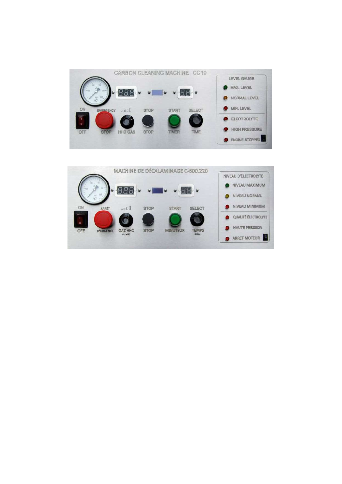
A mini-display is located in the middle of the control panel. The mini-display continuously
circles across preconfigured screens, while each display is shown for approximately 8
seconds, to present the following information to the operator:
•Current time (hours : minutes : seconds)
•Daily cumulative work hours value (hours : minutes : seconds)
•Cell temperature value (deg C)
•Machine connection status, Wi-Fi signal information, server connection information
•Wi-Fi access point information
Mini-display
The normal stop of HHO gas production is performed by pressing the black –or red lit in
some variants –STOP button, located immediately to the right of the HHO gas regulator
potentiometer. To minimise the electrical and thermal stress on the system during the
normal shutdown, it is recommended that the HHO gas production is reduced to zero by
turning the HHO gas regulator fully counterclockwise, and only then pressing the Stop
button.
The START button is located to the right of the Stop button. Pressing the START button
commences the production of HHO gas, provided the gas production setpoint is set to a
value greater than zero, and all safety conditions are cleared.
Similarly to the normal Stop procedure described above, to minimise the electrical and
thermal stress on the system during the normal start, it is recommended that the HHO gas
production regulator is initially set to zero by turning the HHO gas regulator fully counter-
clockwise, then the Start button is pressed, and only then the HHO gas production regulator
is turned clockwise to reach the desired value.
The Timer set dial is located to the right of the Start button. The desired HHO gas production
time interval is set by rotating the dial. The time interval is set in minutes. The available
timer range is 0-99 minutes.
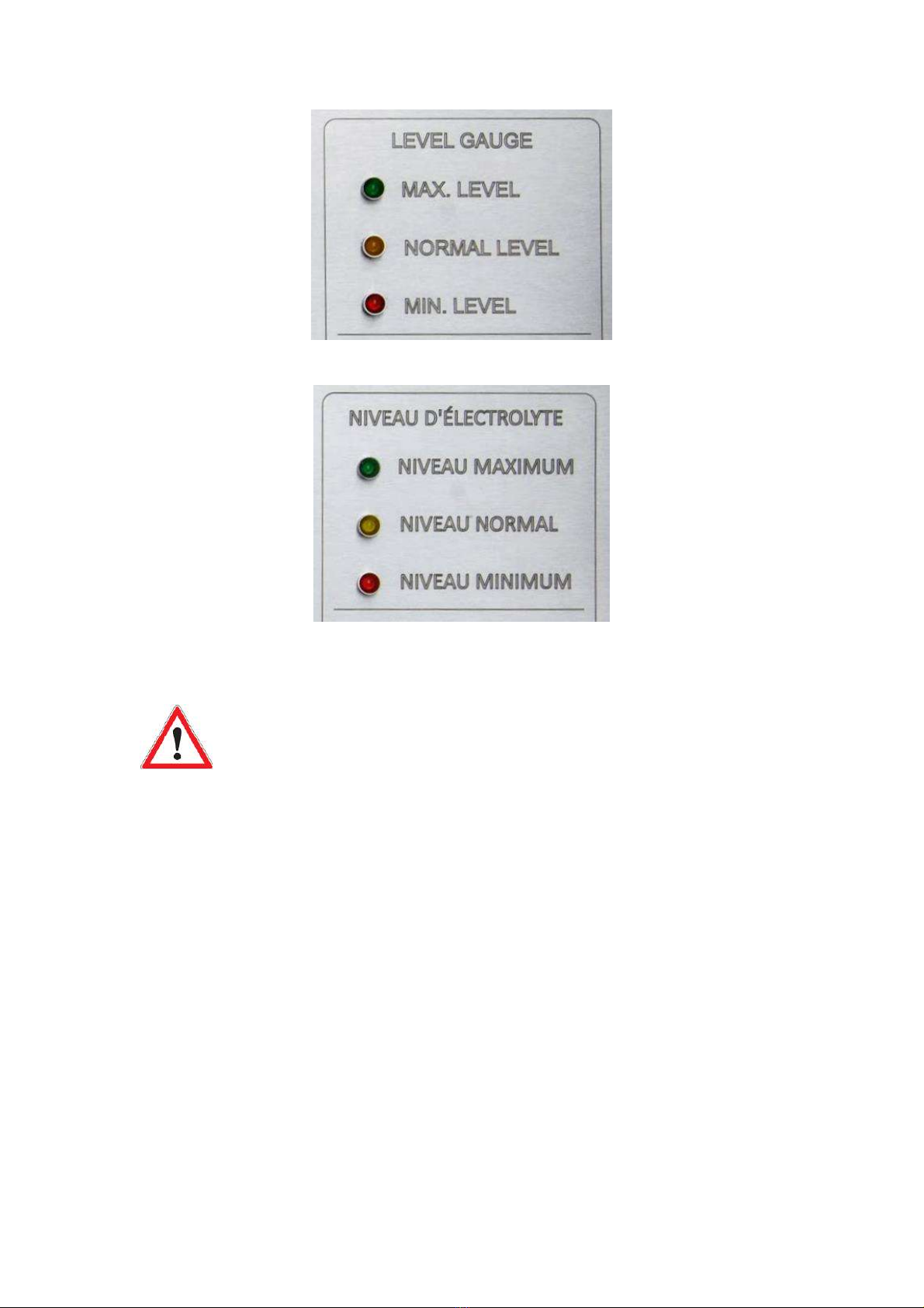
The block of signal LEDs is located on the right-hand side end of the Control Panel.

User Manual Carbon-cleaning machine ANTISMOG
7
Continuous and Timed production modes
Depending on the requirements, the HHO machine can be operated in Continuous or Timed
production mode. The continuous production mode is useful when the gas needs to be
produced for prolonged time periods without interruption, such as for boiler gas co-
combustion, burner, or welding applications.
To start the machine in the Continuous production mode, set the timer value to zero, and
press the Start button to commence production. Set the desired gas volume by adjusting the
HHO gas volume regulator. The gas production is stopped by reducing the gas production
volume setting to zero, then pressing the Stop button.
Attention! Risk of overheating!
In continuous gas production mode, at the gas production rate set at
maximum value, in the hot environment on under direct sunlight, monitor
closely the cell temperature. If the cell temperature value approaches 65
degrees C, lower the gas production rate and/or relocate the machine to
cooler surroundings. If the machine tripped on overtemperature
protection, let the machine on stand-by, with main switch on and no gas
production, for 30 minutes. In any case, do not exceed the continuous
production time of 99 minutes (approximately 1.5 hours) on maximum gas
production setting.
To start the machine in the Timed production mode, set the timer value to the required
value (between 1-99), and press the Start button to commence production. Set the desired
gas volume by adjusting the HHO gas volume regulator. The gas production can be stopped
at any time by reducing the gas production volume setting to zero, then pressing the Stop
button.
In Timed mode, when the set time period has elapsed, an audible alert informs the operator
about the end of the procedure, and the timer display shows zero. Turn the gas production
dial to zero, then press the Stop button, to complete the sequence. The last selected timer
setting will be shown on the Timer display.
Operating sequence
The standard operating sequence for the vehicle engine carbon cleaning treatment is the
following. Adjustments can be made by the operator depending on specific client’s
requirements.
Ensure that the target vehicle does not have obvious mechanical problems, such as low
engine oil level, low cooling liquid level, engine warning indicator On, DPF warning indicator
On, etc. Apply vehicle’s parking brake.

User Manual Carbon-cleaning machine ANTISMOG
8
Position the carbon-cleaning machine in proximity of the vehicle. Apply both wheel brakes
on the carbon-cleaning machine.
Connect the machine to a suitable, reliable, suitably fused power source.
Electrical standard for 50 Hertz countries:
220-240 Volt single-phase 16 Amp 3-pin ECEEC power socket.
Electrical standard for 60 Hertz countries
220-240 Volt two-phase 20 Amp 3-pin NEMA 6-20 power socket.
In case the machine will be operated in an unsupervised mode, connect the red and black
clips to the car battery, strictly observing the polarity.
Loosen the bracket holding the air admission duct of the vehicle, after the air filter, and slip
the hard tip of the gas supply hose into the air admission duct by 15-20 cm in the direction
of the airflow.
Hydrogen delivery hose placement in the air admission duct
Start the vehicle engine.
Turn on the carbon-cleaning machine by pressing the ON/OFF button on the left of the
control panel.
In case the machine will be operating in the Timed Mode, set the required treatment
duration by rotating the dial of the timer. The timer setting in minutes is displayed on the
monitor above the dial.
Briefly press the START button. Wait for the START button to light up.
Set the required gas volume by rotating the dial labelled HHO gas. The gas production
setting in litres per minute is displayed on the monitor above the dial.
In case the machine is operating in the Timed Mode, the timer value will start going down.
The display shows the treatment time remaining.

User Manual Carbon-cleaning machine ANTISMOG
9
Once the timer value reaches zero, the gas production will stop, and an audible signal is
sound to alert the operator.
Press the STOP button to stop the cycle the to reset the timer. The timer value returns to the
previously set number.
Switch off the car engine, retract the gas delivery hose from the air admission duct, and
tighten the air admission duct holding backet.
A typical setup for carbon-cleaning of a car
Monitoring, control, and alarm indicators
Electrolyte level
The three LED indicators on the upper right side of the control panel are the electrolyte level
indicators. The electrolyte level is indicated as follows.
GREEN: The electrolyte is at the maximum level; the machine operates normally. Do not add
electrolyte.
YELLOW: The electrolyte is at the nominal working level; the machine operates normally. No
need to add electrolyte, but the top-up of electrolyte might be required soon.
RED: The level of electrolyte is low; the machine cannot be operated. Add one (1) litre of
operational electrolyte (rose-coloured solution).

User Manual Carbon-cleaning machine ANTISMOG
10
Level Indicator block variant in English
Level Indicator block variant in French
Once the low electrolyte level RED indicator is on, add no more than one
(1) litre of the operating electrolyte solution. Use the calibrated funnel
(included in the kit) to pour electrolyte into the electrolyser cell.
Do not exceed the stated volume! Do not overflow!
Maintenance and safety indicators
The three LED indicators on the lower right side of the control panel are the electrolyte
quality, high pressure alarm, and engine stopped indicators. The information presented by
means of these three indicators can be interpreted as follows.
Electrolyte quality indication
The electrolyte quality red LED indicator is On when the machine is in standby mode. This is
normal. Once the machine is in gas production mode, the electrolyte quality LED goes Off
immediately or after a few minutes of gas production.
If, after 15 minutes of gas production, the electrolyte quality LED is still On, this is an
indication of poor quality of electrolyte. The electrolyser cell needs to be emptied and
refilled with fresh electrolyte at the earliest opportunity.

User Manual Carbon-cleaning machine ANTISMOG
11
Attention! The electrolyte quality indicator LED must be Off during the
normal operation of the machine. Empty the electrolyser cell and refill it
with fresh concentrated electrolyte (transparent solution).
Excess gas pressure indication
The high-pressure red LED indicator is Off during the standby and the normal operating of
the machine. If the pressure indicator is On, this is an indication of the gas pressure in the
electrolyser cell being outside of the safe range due to the inability of the produced gas to
exit the electrolyser cell. Switch off the machine and remove the obstacle, e.g. blocked or
pinched hose.
As an additional safety measure, an analogue manometer is provided. The manometer is
located on the upper left of the operator control panel. The nominal working pressure of the
machine is in 1.5-2.0 bar. It is a good practice for the operator to check the manometer
readings from time to time, to ensure there is an unobstructed flow of gas from the machine
to the vehicle engine.
The overpressure safety trip value is set for 0.25 bar. The machine will stop the production is
the gas pressure reaches the value of 0.25 bar. In an unlikely event of a faulty pressure
sensor, the machine must be manually stopped if the pressure value indicated by the
analogue manometer reaches 0.3 bar.
Attention! Stop the machine immediately if the manometer indication
reaches 0.3 bar. Do not restart the operation of the machine until the
obstruction to the free gas flow is removed, and the free gas flow is re-
established.
Engine stop indication
The machine can be operated in an unsupervised mode, giving the operator the freedom to
work on other scope, while the carbon-cleaning is taking place. The engine stop safety
feature ensures that the gas production is stopped in case the target vehicle engine is not
running.
The switch to the right of the engine stop LED indicator allows the operator to select if the
machine is operated in supervised or unsupervised mode. The selector position “0”
corresponds to the unsupervised mode. The selector position “1” indicates the supervised
mode.

User Manual Carbon-cleaning machine ANTISMOG
12
Attention! Always select the unsupervised mode, selector position “0”, if
the operator is not physically present during the full duration of the
carbon-cleaning service.
General safety guidelines
Hydrogen is a highly flammable gas, therefore some general safety precautions must be
observed.
Prior to commencement of work, examine the overall working area and remove any
potential sources of flame, heat, or ignition. It is forbidden to operate the machine in a fire-
hazardous environment.
While working with the corrosive liquids, such as the electrolyte, it is recommended to wear
safety goggles and rubber or silicon gloves adequate for the working environment.
All heavy moving objects should be secured prior to commencement of work. The vehicle
parking brake should be applied. Both wheel brakes of the carbon-cleaning machine must be
applied.
The nominal operating conditions of the carbon-cleaning machine are 0-40 deg C ambient
temperature, up to 90% air humidity.
Attention! Do not operate the machine if the produced gas is not
immediately consumed, e.g. by admission into the running engine, or
into ignited welding burner. The uncontrolled accumulation of the gas is
highly explosive and can cause injury or death.
Prior to commencement of work, examine the length of the gas delivery hose to ensure
there are no blockages, knots, or pinches of the gas hose that might prevent or obstruct the
gas flow from the machine to the vehicle engine.
Maintenance and consumables
To ensure safe and efficient operation of the machine, and to prolong the life of the
machine, it is recommended to follow the following simple maintenance practices.
Electrolyte changes
The machine is delivered either pre-filled with electrolyte, or empty with chemicals for
preparation of 15 litres of electrolyte by the user. All machines are fully tested at the factory,

User Manual Carbon-cleaning machine ANTISMOG
13
including 3-day continuous gas production stage, therefore small quantity of electrolyte may
still be present in the cell, this is normal.
Similarly to the car engine, the new electrolyser cell needs to be “run in”. The first load of
electrolyte needs to be drained, properly discharged, and replaced by a fresh electrolyte
load, after the initial 1-3 months of operation.
To drain the electrolyte, first connect a suitable hose to the drain nipple at the back of the
machine and make arrangements for collecting and disposing of the used electrolyte. The
machine might need to be elevated to allow for safe collection of the used electrolyte. Then
unscrew the electrolyser cell reservoir cap, located behind the swing door at the back of the
machine, to allow pressure equalisation in the reservoir. Finally open the drain valve at the
bottom of the back panel.
Drain valve at the back of the machine
Tip. Monitor the colour of the used electrolyte. A light-yellow colour
indicates normal operation of the electrolyser cell. A brownish or reddish
tint of the used electrolyte indicate the presence of impurities or rust in
the electrolyser cell. Rinse the inside of the electrolyser cell with clean tap
water 2-3 times, before filling it with fresh electrolyte.
Preparation of electrolyte
To prepare the electrolyte, mix 14.5 litres (3.8 Gallons US) of distilled water with 2 kg of
high-purity potassium hydroxide (KOH). Add the KOH to the distilled water slowly while
constantly mixing the solution. The resulting solution will heat up.
Attention! Always pour the distilled water in a suitable reservoir FIRST,
then add KOH. Reversing the order may cause an uncontrolled violent
chemical reaction.

User Manual Carbon-cleaning machine ANTISMOG
14
When pouring the electrolyte into the hydrogen cell, always use the calibrated funnel, or the
calibrated hose, provided in the kit. This will slow down the rate of flow of electrolyte,
allowing the air to escape form the cell, and prevent the cell overflow.
Gas dryer water level adjustment
The water level in the gas dryer (“bubbler”) needs to be initially set at the level between ½
and ¾ of the height of the transparent reservoir tank. As the gas dryer performs its function
during the gas production, some of the moisture is absorbed from the raising gas bubbles,
and the level of liquid in the tank will rise. Once the liquid level in the gas dryer is visibly
above the ¾ of the tank height, unscrew the bottom (transparent) part of the gas dryer and
safely dispose of some of the liquid.
Gas dryer level settings
Attention! Never allow the liquid level in the gas dryer reservoir raise all
the way to the top and touch or cover the output valve. This would block
the gas flow and may result in machine tripping on overpressure.
Tip. When replacing the liquid in the gas dryer reservoir, add 3-4 drops of
anti-foam agent, provided in the kit, to the distilled water, to prevent
foam forming at the top and blocking the gas output opening. Operating
electrolyte can also be used to fill the gas dryer tank. The operating
electrolyte already contains the required quantity of anti-foam agent.

User Manual Carbon-cleaning machine ANTISMOG
15
Gas diffuser replacements
The gas diffuser breaks the gas flow stream into a series of small bubbles, in order to
facilitate the moisture absorption in the gas dryer tank. The gas diffusers are consumables.
Monitor the state of the gas diffuser regularly. If the surface of the gas diffuser becomes
damaged, replace with a new diffuser.
To replace the gas diffuser, unscrew the bottom (transparent) part of the gas dryer and pull
the diffuser nipple out of the gas hose. Insert the new gas diffuser into the gas hose and
screw the gas dryer reservoir back on.
Gas diffuser placement in the gas dryer
Wi-Fi and Logger configuration
Depending on the model, your carbon-cleaning machine may be equipped with a data logger
and a license management system. The Wi-Fi module enables these additional
functionalities:
•Usage of the equipment in a pay-per-use contract;
•Remote and local access to machine work schedule and reports;
•Remote equipment diagnostics;
•Over-the-air firmware updates;
The C-600 Wi-Fi module can be configured using a smartphone, tablet, or a laptop computer,
by performing the following steps.
Open the ‘Wi-Fi’ or ‘Network’ configuration settings applet on the smartphone, tablet, or
laptop, to scan for available networks and select the default hotspot network named
‘ANTISMOG’.

User Manual Carbon-cleaning machine ANTISMOG
16
When prompted for password, enter the default password sequence: ‘12345678’.
If the configuration applet does not open automatically, open the browsers application and
manually enter the machine’s IP address: ‘192.168.4.1’.
The configuration screen appears:
Wi-Fi configuration screen –Home page
Click on ‘Configure the wifi connection’ link.
A list of available wireless networks will be displayed under the heading ‘WLAN list (refresh if
any missing)’.
Select the required network wireless network by clicking on the name of the network, enter
the password in the window below the network name, and click ‘Connect/Disconnect’
button.

User Manual Carbon-cleaning machine ANTISMOG
17
Wireless connection configuration
Once the connection with the selected network is established, click ‘return to home page’.
A ‘Server connection: OK’ message confirms that the link between the machine and the
server database has been established.
C-600 configuration home page example
Accessing the electrolyser database records
The timestamped data records –such as Start and Stop of gas production, gas production
settings, electrolyte level messages, etc. –are stored in a secure database accessible via an
authorised user account on our portal called MyDataLogger (www.mydatalogger.eu).

User Manual Carbon-cleaning machine ANTISMOG
18
In cases when the machine is not connected to a wireless network, the records for a limited
time period, usually the last 24 hours on the rolling basis, are available directly from the
machine.
Both methods of accessing the data records can be used interchangeably, depending on the
needs of the user.
Web access
Using a smartphone, tablet or a computer with an Internet connection, in a browser window
type the address of the database –www.mydatalogger.eu –and login to your account using
the User_Name and Password provided by the manufacturer.
C-600 web access screen example
Local access
To access the records stored in the machine’s memory, without Internet access, first connect
to the machine’s access point:
Open the ‘Wi-Fi’ or ‘Network’ configuration settings applet on the smartphone, tablet, or
laptop, to scan for available networks and select the default hotspot network named
‘ANTISMOG’.
When prompted for password, enter the default password sequence: ‘12345678’.

User Manual Carbon-cleaning machine ANTISMOG
19
If the configuration applet does not open automatically, open the browsers application and
manually enter the machine’s IP address: ‘192.168.4.1’.
C-600 local access screen example

User Manual Carbon-cleaning machine ANTISMOG
20
Contacts
Contact the manufacturer for questions related to warranty, repairs, consumables, or best-
practice usage tips.
Via the contact form on or website:
www.antismog.co
By email:
By phone:
+33 9 53 99 46 31
In person:
ANTISMOG
Chez Station F, 15 parvis Alan Turing
75013 Paris
France
This manual suits for next models
2
Table of contents
Popular Cleaning Equipment manuals by other brands

Mod-U-Blast
Mod-U-Blast M2000-4C Operation & maintenance manual

System Cleaners
System Cleaners S3 manual

Dover
Dover Hydro systems CCS 9900 Series quick start guide

InterVac
InterVac VacPort A900 Installation and operating manual

abc
abc Triple Crown Modular WaterFed Pole manual

Walter
Walter BIO-CIRCLE COMPACT-S 350 owner's manual