MANUAL - SPRAY GUN CLEANERS - UG5000 SERIES Revision 2008-02
8
CLEANING SPRAY GUNS AND CUPS
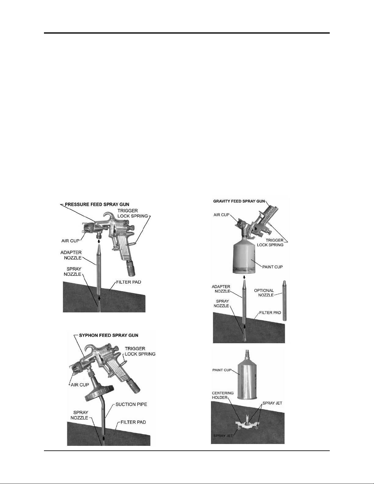
• Loosen the air cap of the spray gun two full turns.
• Lock the trigger in the open position with the Trigger Lock Spring.
• Plug air inlet of spray gun with cap to prevent solvent from entering passage. Caps are supplied
in the accessory kit.
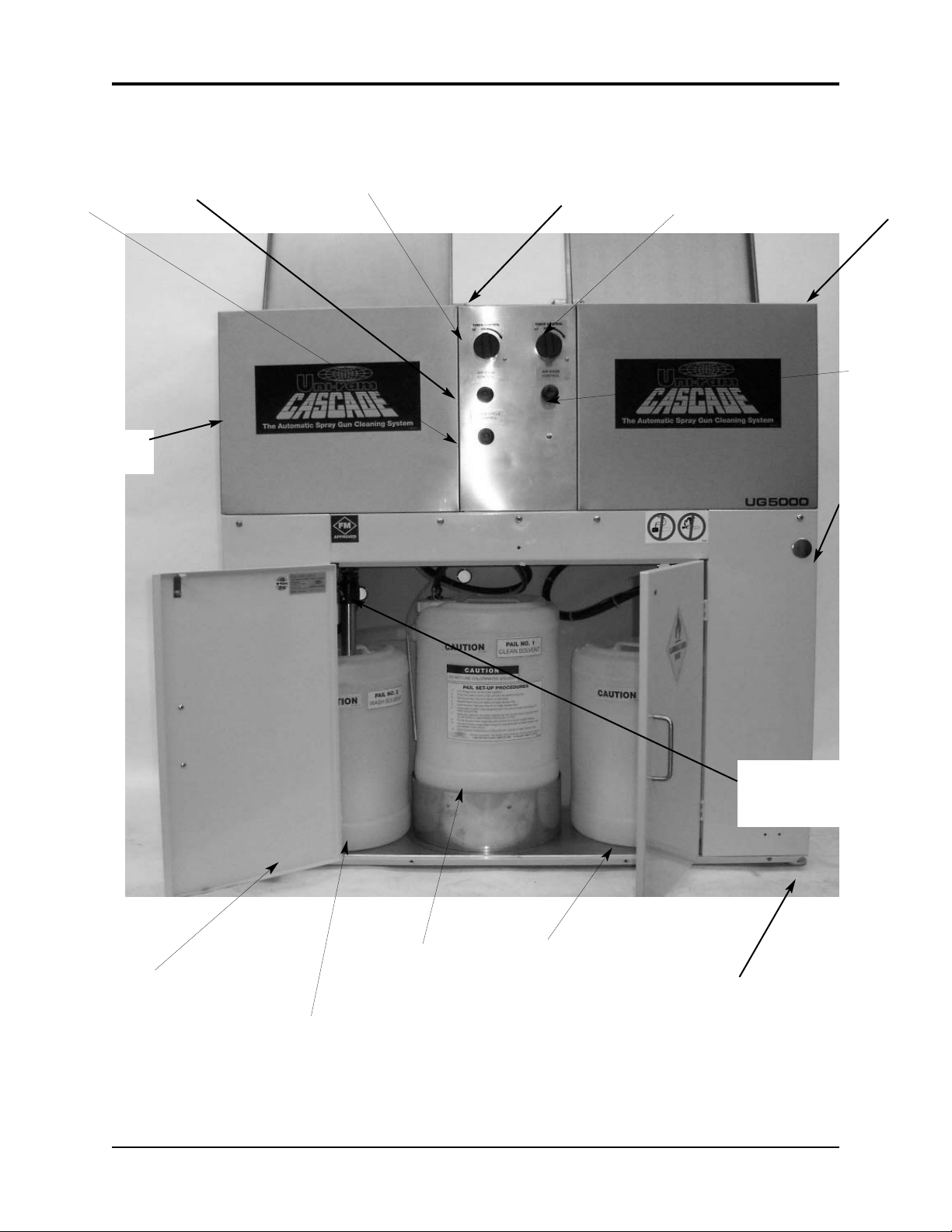
• Place spray guns facing corner jets. Placement depends on type of spray gun. See pictures
below. Place cups onto the low spray jets and cup holders.
CLEANING SPRAY GUNS AND CUPS - continued
• Close the lid and turn the “Auto Wash Timer” knob clockwise to start cleaning. The cleaning
cycle takes about 60 seconds
• Push and hold the "Air Rinse" button for about 3 second to air-rinse the guns.
• Push and hold the "Clean Rinse" button for about 5 seconds to rinse guns with clean sol-
vent. This will send a pre-set amount of clean solvent (100 cc) through the jets. Wait 30 sec-
onds for the Rinse Pump to fully recharge before repeating.
The s
olvent flow per clean-rinse cycle is limited to 100 cc to minimize consumption. This quanti-
ty is usually sufficient to clean the inside pasages of the spray guns.
USING THE MANUAL WASH and MANUAL RINSE FEATURES
• For models with manual wash brush, open the lid and step on the foot pedal (left side). A dedi-
cated pump delivers wash solvent through the brush.
• For models with the Manual Rinse feature, open the lid and step on the foot pedal (right pedal
on two-pedal models). Clean solvent is delivered through the brush.
S
olvent flow through the rinse brush is limited to minimize clean solvent consumption.
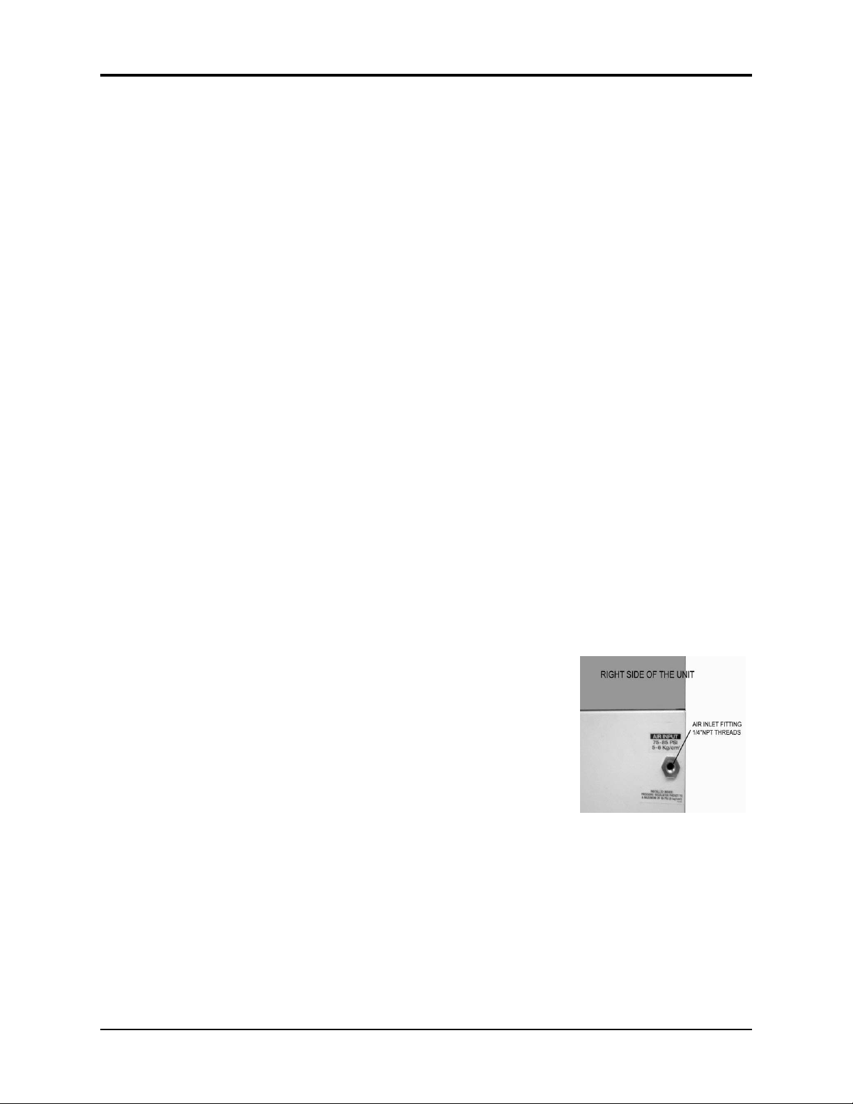
HOSE CLEANING ONLY UG5500E
• Models with this feature to clean a paint feeder hose up to 100 feet (30m) long. Connect the to
the two fittings, one on the front and one on the right side. Rotate the “Mode Selector” to the
right (Horizontal position) and turn the Timer knob clockwise to start the automatic cleaning
cycle.
• To air rinse the hose, push and hold the “Air Rinse” button
• To rinse the hose with the clean solven, push and hold the “Clean Rinse” button for about 5
seconds. This will use about 100 cc of clean solvent. Wait 30 seconds for the Rinse Pump to
fully recharge before repeating.
• Disconnect the hose.
AFTER CLEANING
• Remove the guns and cups from the tank and wipe them dry. Do not store spray guns in the
tank.