Antunes CM-100 User manual

®
CM-100
Owner’s Manual
Cheese Melter
www.antunes.com
USE R.O. WATERSUPPLY ONLY
Manufacturing Number
9100416, 9100418,
CAUTION: Read all instructions before using the unit.
Original Instructions
P/N 1011175 Rev. H 08/20
IPX3
RATING
Mfg No. 9100416 ONLY Certications
9100418 ONLY Certications

®
P/N 1011175 Rev. H 08/20
2
Overview
This unit is intended to be used for
commercial applications, for example:
in kitchens of restaurants, canteens,
hospitals and in commercial enterprises
such as bakeries, butcheries, etc., But not
for continuous mass production of food.
Before Use
This manual contains safety, installation,
and operating procedures for the unit.
Read and understand it completely before
installing or operating the unit. Keep this
document for reference. If the unit changes
ownership, this manual must accompany it.
In Case of Damage
If the unit arrives damaged, le a claim
with the carrier immediately. Save
all packing materials when ling a
claim. Freight damage claims are the
responsibility of the purchaser and are not
covered under warranty.
Website
www.antunes.com
Service/Technical
Assistance
In Case of Damage
If any parts are missing or damaged,
problems with the installation or operation
of this product contact Antunes Customer
Service immediately at +1-877-392-7856
(toll free).
Fill in the information in the next section
and have it ready when calling for
assistance. The serial number is on the
specication sticker located on the system.
Equipment Information to Save
Purchased from:
Date of purchase:
Model number:
Serial number:
Manufacturing number:
Authorized Service Agency
Name:
Phone No:
Address:
Table of Contents
Overview 2
Before Use 2
In Case of Damage 2
Website 2
Service/Technical Assistance 2
In Case of Damage 2
Equipment Information to Save 2
Authorized Service Agency 2
Safety Information 3
Installation 3
Maintenance 3
Service 3
Specications 4
Installation 5
Unpacking 5
Plumbing 5
Operating Instructions 6
Preparing Unit 6
Cooking Procedure 6
Hi-Limit Thermostat 6
Maintenance 7
Daily Cleaning 7
Monthly Cleaning 7
Calibration 8
Troubleshooting 9
Troubleshooting (Continued) 10
Wiring Diagram 11
Replacement Parts 12
Parts List 12
Exploded Views 13
Notes 15
WARNING
These appliances are intended to be
used for commercial applications - not
for continuous mass production of food.

®
P/N 1011175 Rev. H 08/20 3
Safety Information
Installation
yRead and understand all instructions
before installing or using the unit.
yInstall this unit to comply with the
basic plumbing code of the Building
Ocials and Code Administrators,
Inc. (BOCA) and the Food Service
Sanitation Manual of the Food
and Drug Administration (FDA).
yInstall and locate the equipment
only for its intended use as
described in this manual.
WARNING
ELECTRICAL SHOCK HAZARD.
Failure to follow the instructions in
this manual could result in serious
injury or death.
Do not modify the power supply cord
plug. If it does not t the outlet, have
a proper outlet installed by a qualied
electrician.
Electrical ground is required on this
appliance.
Check with a qualied electrician if you
are unsure if the appliance is properly
grounded.
Do NOT use an extension cord with this
product.
The unit should be grounded according
to local electrical codes to prevent
the possibility of electrical shock. It
requires a grounded receptacle with
separate electrical lines, protected by
fuses or circuit breaker of the proper
rating.
NEVER unplug the power cord while
the unit is running. Use the proper
shutdown procedure before unplugging
the power cord.
Operation
yThe unit is furnished with
a properly grounded cord
connector. Do not attempt to
defeat the grounded connector.
yDo not operate the unit if it has
been damaged or dropped, if it
has a damaged cord or plug, or
if it is not working properly.
yDo not block or cover any
openings on the equipment.
yDo not immerse the cord,
unit, or plug in water.
yKeep the cord away from
heated surfaces.
yDo not allow the cord to hang over
the edge of a table or counter.
yThis appliance is not to be used
by persons (including children)
with reduced physical, sensory
or mental capabilities, or lack
of experience and knowledge
unless they have been given
supervision or instruction.
yChildren being supervised are
not to play with the appliance.
yBread may burn. Therefore toasters
must not be used near or below
curtains or other combustible walls
and materials. Failure to maintain
safe operating distances may cause
discoloration or combustion.
yWhen opening the door of
the cooking compartment
hot steam can come out.
Maintenance
yDo not use abrasive materials;
they can damage the unit’s
stainless steel nish.
yDo not use corrosive chemicals
in this equipment.
yChlorides or phosphates in cleaning
agents (e.g., bleach, sanitizers,
degreasers, and detergents) can
permanently damage stainless
steel equipment. The damage is
usually in the form of discoloration,
dulling of the metal surface nish,
pits, voids, holes, or cracks.
This damage is permanent and
is not covered by warranty.
yAlways use a soft, damp cloth for
cleaning. Rinse with clear water and
wipe dry. When required, always rub
in the direction of metal polish lines.
yRoutine cleaning should be
performed daily with soap and water.
yRub o nger marks and smears
using soap and water.
yDo not clean unit or components
in a dishwasher unless specically
specied in the cleaning instructions.
yDo not clean the unit with a
water jet or steam cleaner.
Service
yInspection, testing, and
repair of electrical equipment
must be performed only by
qualied service personnel.
yTo avoid possible personal injury
and/or damage to the unit, all
inspections, tests, and repair of
electrical equipment should be
performed by qualied personnel
ONLY. Contact Antunes Technical
Service for adjustment or repair.
yTurn the power o, unplug the power
cord, and allow unit to cool to room
temperature before performing
any service or maintenance.
yIf the supply cord is damaged,
it must be replaced by the
manufacturer, its service agent, or
a similarly qualied person in order
to avoid an electrical hazard.
yCleaning and user maintenance
shall not be made by children
without supervision.
WARNING
To avoid scalding, do not use loaded
containers with liquids or cooking
goods which becomes uid by heating
in higher levels than those which can
be easily observed.

®
P/N 1011175 Rev. H 08/20
4
Specications
Electrical Ratings
ElectricalCord&PlugCongurations
Model &
Mfg. No. Description Conguration
CM-100
9100416 NEMA 6-20P
CM-100
9100418 CEE 7/7
Model &
Mfg. No. Volts Watts Amp Hertz
CM-100
9100416 208 3300 16 50/60
CM-100
9100418 230 3300 16 50/60
Model &
Mfg. No.
Width
(A)
Depth
(B)
Height
(C)
CM-100
9100416
9100418
17 3/8”
(441 mm)
17 5/8”
(448 mm)
8 3/8”
(213 mm)
Dimensions
USE R.O. WATER SUPPLY ONLY
C
A
B

®
P/N 1011175 Rev. H 08/20 5
Installation
Unpacking
1. Remove unit and all packing materials
from the shipping carton. If any
parts are missing or damaged,
contact Antunes Customer Service
IMMEDIATELY at +1-877-392-7856
(toll free).
2. Remove the information packet.
3. Remove all packing materials and
protective coverings.
4. The unit should come with the items
listed below:
yOwner’s Manual
yAuthorized Service Agency Directory
yHandle and Handle Guard
yWater Quick Disconnect Kit
5. Wipe all surfaces of the unit with a hot
damp cloth. Do NOT use a dripping
wet cloth. Wring it out before use.
Remove and wash the Spatula and
Liner (Figure 1) in soap and water
by hand. Rinse with clean water and
allow to air dry.
6. Assemble the Handle and Handle
Guard to the Spatula (Figure 1).
7. Re-install the Spatula.
8. Clean the accessories in hot, soapy
water. Rinse in clear water and allow
to air dry.
9. Reassemble the unit.
10. The unit must be level before use.
When placing the Cheese Melter into
service, pay attention to the following
guidelines.
yMake sure the power switch is o
and the unit is at room temperature
before plugging in the power cord.
yDo not block or cover any
openings on the unit.
yDo not immerse the power
cord or plug in water.
yKeep the power cord away
from heated surfaces.
yDo not allow the power cord to hang
over edge of table or counter.
NOTE: Plug the power cord into the
appropriate power outlet. Refer
tothespecicationplateforthe
proper voltage.
Figure 1. CM-100 Spatula
Figure 2. Quick Disconnect Figure 3. Chimney Drain Tubing
1. Place the unit on a sturdy, level table
or other work surface.
2. Turn o the power.
3. Ensure the line voltage corresponds to
the stated voltage on the specication
label and power cord warning tag.
4. Connect a length of 1/4” (6.5 mm) I.D.
exible tubing (not supplied) to the
bottom of the Chimney as shown in
Figure 3. Secure using a hose clamp
(not supplied). Direct the other end of
the tubing to a drain.
5. Connect the unit to the power supply.
Plumbing
The CM-100 requires installation of a
reverse osmosis ltration system for
supplying water to this equipment. To
purchase the ltration system, contact the
approved equipment distributor.
Flexible water line (not supplied) for water
hookup should be 1/4” (6.5 mm) I.D. to t
the quick disconnect (supplied).
NOTE: It is recommended to install
an in-line water strainer (P/N
7000333) to prevent debris from
entering the solenoid valve.
Debris in the solenoid valve will
cause a leaking condition that is
not covered by warranty.
1. Connect the Flexible Tubing to the
Quick Disconnect Insert using the
supplied hose clamp.
2. Push the Quick Disconnect Insert into
the female tting on the back of the
unit until it clicks.
WARNING
Water pressure must not exceed 25
psi (1.7 kg/cm2 or 172 kPa). Higher
water pressures may cause poor
performance or ooding. To reduce
water pressure, install a water pressure
regulator, and set water pressure to
20–25 psi (1.4–1.7 kg/cm2 or 138–172
kPa).
WARNING
Connect this unit to a cold water supply
line only. Connecting this unit to a hot
water supply line will void the warranty.
USE R.O. WATERSUPPLY ONLY
Direct this end
to a Drain
Chimney
(rear of unit)
Chimney
Drain

®
P/N 1011175 Rev. H 08/20
6
Operating Instructions
Preparing Unit
1. Turn the power on and allow the unit
to preheat for approximately 20-30
minutes.
NOTE:ThegreenReadyLightwillash
duringwarm-up.Theashing
light will become steady when
the unit is up to temperature.
If the Ready Light continues to
ashafterwarm-up,orstartsto
ashduringoperation,seethe
Troubleshooting section in this
manual.
NOTE: Do NOT push the Cycle/Start
button during warm-up. The
ashinggreenReadyLight
indicates the unit is not up to
temperature. If the Cycle/Start
button is pressed while the
greenlightisashing,nothing
will happen.
Cooking Procedure
1. Pull out the Spatula and place the
product to be steamed onto the
Spatula.
2. Push the Spatula fully into the unit.
NOTE: Spatula must be fully inserted in
order to start a steam cycle.
3. Press and release the CYCLE/START
button. The green Ready Light will
come on and remain lit for the entire
steaming cycle.
4. At the end of the steaming cycle
(approximately 7 seconds), an audible
signal will sound until the Spatula
is removed from the unit and the
green Ready Light will turn back on,
indicating the product is ready to be
served.
5. Carefully remove the steamed product
and insert the Spatula back into the
unit.
Hi-Limit Thermostat
A hi-limit thermostat will turn o electrical
power to the Generator and transformer
circuits if the unit overheats. To reset the
Hi-Limit Thermostat, allow the unit to cool
down (approximately 45 minutes). Then
remove the cap located on the bottom
of the unit (Figure 4) and press the reset
button. If the unit continues to shut o
due to overheating, contact your Antunes
Authorized Service Agency.
Figure 4. Operation Controls
Figure 5. Cooking Procedure
WARNING
To avoid injury, be careful when
removing the Spatula. Be sure to allow
steam to escape before putting hands
or face over the steamer.
USE R.O. WATERSUPPLY ONLY
CYCLE
START
START
CYCLE
STEAMING
READY
POWER
USE R.O. WATER SUPPLY ONLY
Power Button
Ready Indicator
Light
Steaming
Indicator Light
Cycle Start Button

®
P/N 1011175 Rev. H 08/20 7
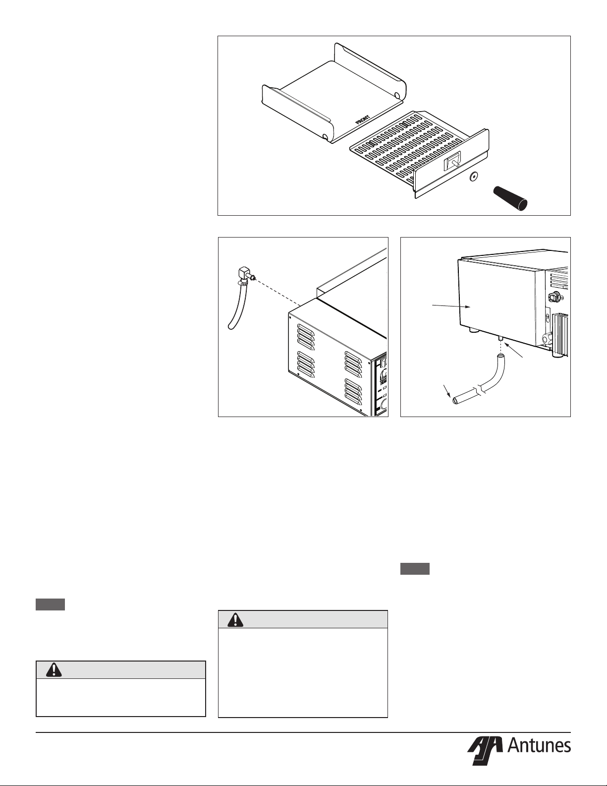
Figure 6. Components
Daily Cleaning
NOTE: Frequency of cleaning is
determinedbywaterconditions,
usage,andwaterltersystems.
1. Turn the unit o, unplug the power cord,
and allow the it to cool down before
proceeding.
2. Check the Water Quick Disconnect
Fitting and all hose clamp connections
for leakage. If leakage is apparent,
tighten all clamps or replace part if
required.
3. Remove the Top Cover, Spatula, and
Liner.
4. Remove Chimney from rear of unit by
sliding upward and away from the unit.
5. Clean the Top Cover, Spatula, Liner, and
Chimney in hot, soapy water by hand.
Rinse in clear water and wipe dry.
Maintenance
WARNING
Turn the power o, unplug the power
cord, and allow the unit to cool to room
temperature before performing any
service or maintenance.
CAUTION
Chlorides or phosphates in cleaning
agents (e.g., bleach, sanitizers,
degreasers, or detergents) can cause
permanent damage to stainless steel
equipment. The damage is usually
in the form of discoloration, dulling of
metal surface nish, pits, voids, holes,
or cracks. This damage is permanent
and is not covered by warranty. Follow
these tips for maintenance of stainless
steel equipment:
yUse a soft, damp cloth for
cleaning, rinse with clear water,
and wipe dry. Always rub in the
direction of metal polish lines.
yOnly use approved cleansers.
yFinger marks and smears should
be removed using soap and water.
yDo NOT use a metal
scraper on grill surfaces
yDo NOT wash any components
of the unit in a dishwasher.
Hand wash ONLY in a
three-compartment sink.
CAUTION
Grill surfaces will be hot. Extreme
care must be taken when operating or
cleaning this unit. Use heat-resistant
gloves when necessary.
NOTE: Do NOT wash in a power washer.
6. Clean the chamber of any product spills.
7. Clean entire unit with a clean, hot, damp
cloth (not dripping wet) and wipe dry.
8. Re-install Chimney, Liner, Spatula, and
Top Cover.
9. Plug in the power cord and test the unit
before returning it to service.
Monthly Cleaning
This unit utilizes an open steam generator.
Water sprayed onto the Generator surface
ashes into steam immediately, but the
minerals in the water do not steam; they stay
on the Generator surface. A small amount
of mineral deposits are needed for proper
operation, but a buildup of excessive mineral
deposits causes poor steaming eciency
and excessive moisture (wet steam) and
will eventually severely hinder the steaming
action.
Cleaning Steam Generator
1. Turn the power o, unplug the power
cord, and allow the unit to cool down.
2. Remove the Top Cover.
3. Remove the Wing Nut and Generator
Cover.
4. Remove the Diuser.
5. Examine all steam ports. If mineral
deposits have formed, place a at
blade screwdriver or wire brush into
the openings. Use a twisting motion to
scrape the openings clean.
NOTE:Ifthemineraldepositscomeo
inakesorlayers,buildupis
excessive.
6. Use a brass or stainless steel wire brush
and small scraper to loosen and remove
excessive deposits from the generator
surface. If deposits are still excessive
and/or dicult to remove, proceed to
Step 7.
7. Pour food safe delimer solution (not
supplied) or white vinegar onto the
Generator surface. Be sure to follow the
delimer manufacturer’s directions for
proper mixture and use. It must be safe
for use on aluminum.
8. Remove the delimer solution from the
Generator and rinse with clear water to
remove all traces of solution.
9. Clean the Spatula Liner, Chimney,
Diuser, Top Cover, and Generator
Cover in hot detergent water. Then rinse
in clear water and wipe dry.
10. Clean steam chamber of any product
spills.
11. Clean the surface of the unit with a hot,
clean, damp cloth (not dripping wet) and
wipe dry.
12. Re-install all parts and fasten the
Generator Cover.
13. Plug in the power cord and water line.
To ensure proper steaming characteristics,
some mineral deposits must be present on
the Generator surface. If during cleaning, the
surface does become free of mineral deposits
(bare aluminum), add plain tap water to
surface and allow to boil o.
In soft water areas, it may be necessary to
add a small amount of calcium/minerals to
the generator surface to season it. This will
ensure proper steaming characteristics by
producing a thin coating of mineral deposits
on the surface. Seasoning mixture consists
of 2 tablespoons baking soda, and 1 cup
water. Pour 1/4 cup of seasoning mixture
onto hot generator. After mixture is converted
to steam, the remaining loose powder can be
removed. Repeat as needed until there is a
thin, white mineral coating on the surface of
the generator.
Liner
Handle
Handle
Guard
Top Cover
Spatula
Chimney
Wing Nut
Generator
Cover
Diuser
Steam
Pots

®
P/N 1011175 Rev. H 08/20
8
Calibration
If the unit does not steam properly
and the water pressure is 20–25 psi,
use the steps below to calibrate the
water volume.
1. With the unit positioned at the edge
of its location surface (counter,
table, etc.), slide the unit forward
approximately 3" to expose the Water
Volume Control on the bottom left
side of the unit (Figure 5).
2. Use a small screwdriver to carefully
and slowly adjust the control. Turning
the control clockwise increases
the amount of water volume used
per cycle and counterclockwise
decreases the amount.
NOTE: The Water Volume Control is
numbered 0-9 and is preset to
6.Witheachturn,theunitwill
beep.
3. Plug in the power cord and test the
unit before returning it to service.
NOTE: If the steamer does not steam
properlyaftercalibration,refer
to the Troubleshooting section
of this manual.
WARNING
Excessive force will damage the Water
Volume Control. Do NOT turn past the
built-in stops on the control or the unit
will be damaged and void the warranty.
CYCLE
START
I
N
C
R
E
A
S
E
D
E
C
R
E
A
S
E
0
9
8
7
6
5
4
3
2
1
I
N
C
R
E
A
S
E
D
E
C
R
E
A
S
E
0
9
8
7
6
5
4
3
2
1
Figure 7. Water Volume Control

®
P/N 1011175 Rev. H 08/20 9
Troubleshooting
Problem Possible Cause Corrective Action
Unit steams, but requires
two or more cycles to melt
cheese.
Generator Surface temperature is too low Verify generator surface temperature to be 380-420°F.
Insucient or excessive calcium deposits
on Generator Surface.
Verify generator surface has a thin calcium coating for
proper steaming. Refer to the Maintenance section of this
manual.
Generator Cover is warped or loose. Verify the Wing Nut is tight. If noticeable steam escapes
around the Generator Cover, replace the cover.
Low water pressure. Verify water pressure regulator is set to 20-25 psi. Adjust
accordingly.
Water volume adjustment is set too low. Calibrate the unit for proper water volume. Refer to the
Maintenance section of this manual.
Generator steam ports are restricted. Verify the steam ports are not restricted. Clean accordingly.
Generator Surface is bare.
Generator Surface must have a thin calcium coating for
proper steaming. Refer to the Maintenance section of this
manual.
Damaged or worn Quick Disconnect.
Generator Surface must have a thin calcium coating for
proper steaming. Refer to the Maintenance section of this
manual.
Damaged or worn Quick Disconnect.
Remove the Quick Disconnect from the rear of the unit. The
white plastic piece should protrude approximately 1/8” from
the metal.
Unit heats but does not
steam.
Low or no water pressure in water line.
Remove the Quick Disconnect Insert from teh rear of the
unit. While holding into an empty cup, press the white
plastic tip for 5 continuous seconds. A strong, steady water
ow should be noted. If so, re-engage rmly into the unit.
If not present, or low pressure, contact your maintenance
person or plumber.
Solenoid valve coil is defective. Contact your local Authorized Service Agency.
Control Board inoperable or problematic.
Quick Disconnect is not fully engaged at
rear of unit or is damaged.
Remove and re-engage the Quick Disconnection rmly until
a click is hear. Replace if damaged.
CYCLE/START button is inoperable. Contact your local Authorized Service Agency.
Optical Switch is not activated.
Ensure the Spatula is fully inserted and engaged the
Optical Switch. Replace the Spatula if it is bent or
damaged.
Optical Switch is inoperable. Contact your local Authorized Service Agency.
Excessive condensation in
food compartment.
Water pressure is too high. Verify water pressure regulator is set to 20-25 psi. Adjust
accordingly.
Water volume adjustment is set too high. Calibrate unit for proper water volume. Refer to the
Installation section of this manual.
WARNING
To avoid possible personal injury and/or damage to the unit, inspection, test, and repair of electrical equipment should be performed
by qualied service personnel. The unit should be unplugged when servicing, except when electrical tests are required. Use extreme
care during electrical circuit tests. Live circuits will be exposed. If the troubleshooting steps listed below do not solve your machine’s
problem, contact an Authorized Service Agency for further assistance.

®
P/N 1011175 Rev. H 08/20
10
Problem Possible Cause Corrective Action
Unit only leaks water when
powered off.
Solenoid Valve is leaking due to debris
trapped within its plunger and seat.
Contact your local Authorized Service
Agency.
NOTE: This condition is not covered by
warranty. To prevent debris from entering a
solenoid, an in-water strainer must be used.
Unit only leaks water when
powered on.
Control Board inoperable or problematic. Contact your local Authorized Service
Agency.
CYCLE/START button shorted.
No heat and the green Ready
Light flashes continuously.
Generator is open. Contact your local Authorized Service
Agency.
Solid State Relay not closing.
Control Board inoperable or problematic.
Loose, burnt, or broken wires in heater
circuit.
Circuit is wired incorrectly.
Unit does not operate, power
switch is on, but light is off.
Unit unplugged. Plug power cord into the appropriate outlet.
Circuit breaker is off. Reset the circuit breaker.
Power cord defective or inoperable. Contact your local Authorized Service
Agency.
Power switch defective or inoperable.
Green Ready Light and yellow
Steaming Light turn on and off
intermittently.
Hi-Limit Thermostat is tripping because of an
overheating Generator.
Verify the Generator Surface temperature
is 380–420°F. If temperature is above
420°F, contact your maintenance person or
Authorized Service Agency.
Hi-Limit Thermostat is tripping prematurely. If the Hi-Limit Thermostat trips within 380–
420°F, contact your local Authorized Service
Agency.
Troubleshooting (Continued)

®
P/N 1011175 Rev. H 08/20 11
WiringDiagram(MfgNo.9100416)

®
P/N 1011175 Rev. H 08/20
12
WiringDiagram(MfgNo.9100418)

®
P/N 1011175 Rev. H 08/20 13
Item
No.
Part # Description Qty.
1 0506007 Cavity Liner 1
2 2100107 Spatula Handle 1
3 2100249 Spatula Handle Guard 1
40700452 Power Cord (Mfg No. 9100416) 1
0700453 Power Cord (Mfg No. 9100418) 1
5 3010116 Weld Nut #8-32 4
6 3010146 Weld Stud #4-40 x 7/8" 4
7 3040125 PEM Stud #4-40 x 5/8" 2
8 0400251 Strain Relief (Mfg No. 9100418) 1
9 0400138 Locknut Conduit 1
10 3060153 Self-Clinching Stud #6-32 x 3/8" 1
11 7000652 Solid State Relay, 50A 1
12 4050180 Heat Sink 1
13 308P104* Mach. Screw #8-32 x 3/8"
14
7000245
Generator, 208V, 3800W
(Incl. #14, 37, 38, 39 & 65)
(Mfg. No. 9100416)
1
7000246 Generator 230V/3300 W
(Mfg. No. 9100418) 1
15 7000319 Transformer 1
16 300P102* Speed Nut, #8-32
17 1001433 Control Label 1
18 7000841 Momentary Switch Assy. 1
19 4010231 Rocker Switch, 25A 1
20 4070156 Varistor Board 1
21 4050135 Thermocouple, Type J 1
22 0011123 Solenoid Valve Assy. 24 VAC 1
23 2080117 Quick Disconnect, 1/8" NPT 1
24 0503171 Quick Disconnect Plate 1
25 362P102* Lockwasher -
26 2140159 Tape Pipe Tread 2
27 2040103 Male Connector, 1/4" x 1/8" NPT 1
28 2040146 Female Tee Fitting, 1/4" x 1/8" NPT 1
29 2040145 Female Elbow Fitting, 1/4" x 1/8"
NPT 1
30 2000203 Restrictor Tube 1
31 2000236 Inlet Tube 1
32 308P124* Mach. Screw #8-32 1
33 308P143* KEPS Hex Nut #8-32 2
34 308P103* Tap Screw, #8-32 x 1/4" 16
35 0503433 Generator Cover 1
37 325P170* Wing Nut, 1/4"-20 1
Replacement Parts
Parts List
(See Exploded Views for more information)
NOTICE
Use only genuine Antunes replacement parts in this unit. Use
of parts other than those supplied by the manufacturer will void
the warranty.
Item
No.
Part # Description Qty.
38 0300129 Stud Cover 1
39 306P134* Mach. Screw #6-32 x 3/8" 3
40 0503472 Hi-Limit Support Bracket 1
41 7000846 Water Fitting Kit
(Incl. #28, 29, 30 & 31) 1
42 0021654 Chimney 1
43 0012654 Optical Switch Assy. 1
44 2100247 Knob 1
45 2100250 Handle Guard 1
46 1001192 Label, Caution 1
47 0506011 Top Cover 1
49 0506008 Thermocouple Retainer 1
50 4070171 Main Board 1
51 304P105* Hex Nut, #4-40 9
52 2180145 Bumper Cover 4
53 7000130 Bumper Recess 4
54 310P136* Mach. Screw #10-32 x 1/4" 4
55 4030314 Hi-Limit Thermostat 1
56 0505999 Bottom Cover 1
57 0505997 Control Housing Cover 1
58 0505998 End Housing Cover 1
59 7000136 Terminal Block 1
60 306P101* Hex Nut #6-32 2
61 306P123* Mach. Screw #6-32 x 7/8" 2
62 1000967 Marking Label 1
64 308P120* Mach. Screw #8-32 x 5/8" 4
65 0503431 Steam Diffuser 1
66 4060107 Cable Tie 1
67 1000402 Label, Increase/Decrease 1
68 1001062 Label, Connections 1
69 0021655 Spatula 1
70 0502199 Spacer 2
71 7000446 Pipe, 3.625" Lg. (See note below) 1
72 0700807 Wire set 1
73 1001427 Wiring Diagram (Mfg No. 9100416)
74 1002825 Wiring Diagram (Mfg No. 9100418) 1
80 0014018 Assembly, Capacitor 1
* Available only in packages of 10.
NOTE: Always use thread seal tape on threads and tighten
until very snug.

®
P/N 1011175 Rev. H 08/20
14
Exploded Views
Exploded View #1
USER.O. WATER SUPPLY ONLY
42
14
65
38
35
47
13
37
46
45
44
34
58
69
1
43
21
17
52
54
53
34
56
50
51
18
67
19
49
40
34
16
51
20
34
11
3
2
12
59
80
61
4
8
71
31
41
28
30
29
36
62
15
55
57
22
34
39
14
(P/N 0100280)
74
(P/N 0200311)
75
(P/N 0200310)
79
(P/N 0200324)
77
(P/N 3080104)
76
(P/N 0021923)
78
(P/N 0200323)
77
(P/N 3080104)
ITEMS SPECIFIC TO MFG. NO. 9100417

®
P/N 1011175 Rev. H 08/20 15
NOTES

Limited Warranty
Equipment manufactured by Antunes has been constructed of the nest materials available and manufactured to
high quality standards. These units are warranted to be free from electrical and mechanical defects for a period of
one (1) year from date of purchase under normal use and service, and when installed in accordance with manufac-
turer’s recommendations. To insure continued operation of the units, follow the maintenance procedures outlined
in the Owner’s Manual. During the rst 12 months, electromechanical parts, non-overtime labor, and travel ex-
penses up to 2 hours (100 miles/160 km), round trip from the nearest Authorized Service Center are covered.
1. This warranty does not cover cost of installation, defects caused by improper storage or handling prior to plac-
ing of the Equipment. This warranty does not cover overtime charges or work done by unauthorized service
agencies or personnel. This warranty does not cover normal maintenance, calibration, or regular adjust-
ments as specied in operating and maintenance instructions of this manual, and/or labor involved in moving
adjacent objects to gain access to the equipment. This warranty does not cover consumable/wear items. This
warranty does not cover damage to the Load Cell or Load Cell Assembly due to abuse, misuse, dropping of
unit/shock loads or exceeding maximum weight capacity (4 lbs). This warranty does not cover water con-
tamination problems such as foreign material in water lines or inside solenoid valves. It does not cover water
pressure problems or failures resulting from improper/incorrect voltage supply. This warranty does not cover
Travel Time & Mileage in excess of 2 hours (100 miles/160 km) round trip from the nearest authorized service
agency.
2. Antunes reserves the right to make changes in design or add any improvements on any product. The right
is always reserved to modify equipment because of factors beyond our control and government regulations.
Changes to update equipment do not constitute a warranty charge.
3. If shipment is damaged in transit, the purchaser should make a claim directly upon the carrier. Careful inspec-
tion should be made of the shipment as soon as it arrives and visible damage should be noted upon the car-
rier’s receipt. Damage should be reported to the carrier. This damage is not covered under this warranty.
4. Warranty charges do not include freight or foreign, excise, municipal or other sales or use taxes. All such
freight and taxes are the responsibility of the purchaser.
5. THIS WARRANTY IS EXCLUSIVE AND IS IN LIEU OF ALL OTHER WARRANTIES, EXPRESSED OR
IMPLIED, INCLUDING ANY IMPLIED WARRANTY OR MERCHANTABILITY OR FITNESS FOR A PARTICU-
LAR PURPOSE, EACH OF WHICH IS HEREBY EXPRESSLY DISCLAIMED. THE REMEDIES DESCRIBED
ABOVE ARE EXCLUSIVE AND IN NO EVENT SHALL ANTUNES BE LIABLE FOR SPECIAL CONSEQUEN-
TIAL OR INCIDENTAL DAMAGES FOR THE BREACH OR DELAY IN PERFORMANCE OF THIS WAR-
RANTY.
The warranty does not extend to:
yDamages caused in shipment
yInstallation of electrical service
yInstallation, calibration, or adjustment
yNormal maintenance outlined in this manual
yConsumable parts such as egg rings, gaskets, rubber feet, labels, O-rings, light bulbs, etc.
yMalfunction resulting from improper service or maintenance
yDamage caused by improper installation, improper use, abuse, or careless handling
yDamage from moisture coming in contact with electrical components
yDamage from tampering with, removal of, or changing preset controls or safety devices
yDamage caused by parts or components not provided by Antunes
+1 (630) 784-1000
+1 (800) 253-2991
+1 (630) 784-1650
+86-512-6841-3907
+86-512-6841-3637
®
This manual suits for next models
2
Table of contents
Other Antunes Kitchen Appliance manuals