P/N 1011572 Rev E 01/21
10
Monthly Cleaning
This unit utilizes an open steam
generator. When introduced, water
immediately vaporizes creating a burst of
steam, leaving behind any minerals that
had previously been dissolved. Though a
small amount of minerals are necessary
for proper operation, excessive amounts
will cause poor steaming and may
damage the generator.
NOTE: Failure to periodically clean
the generator may result in
poor steamer performance and
take multiple retherm cycles to
heat the food.
NOTE: Frequency of cleaning
is determined by water
conditions, usage and water
lter systems Recommended
water hardness, or Total
Dissolved Solids (TDS),
should not exceed 60 ppm
(parts per million) (<3 GPG).
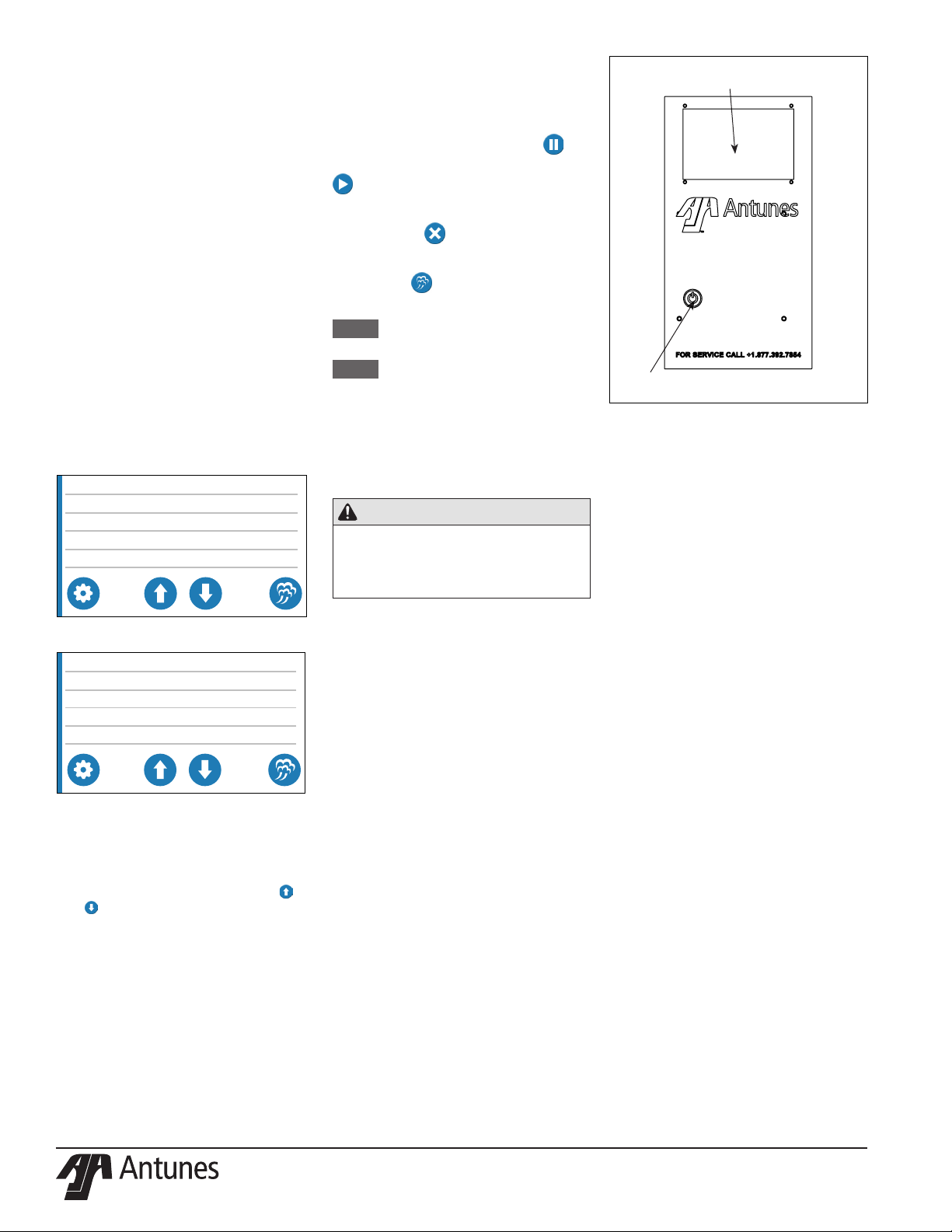
1. Press the Power button to turn the
unit o. The unit enters a cool-
down mode and will shut down
automatically.
NOTE: You do not need to wait
until the cool down mode
completes. However, the
unit will be hot so wear heat
resistant gloves during
cleaning.
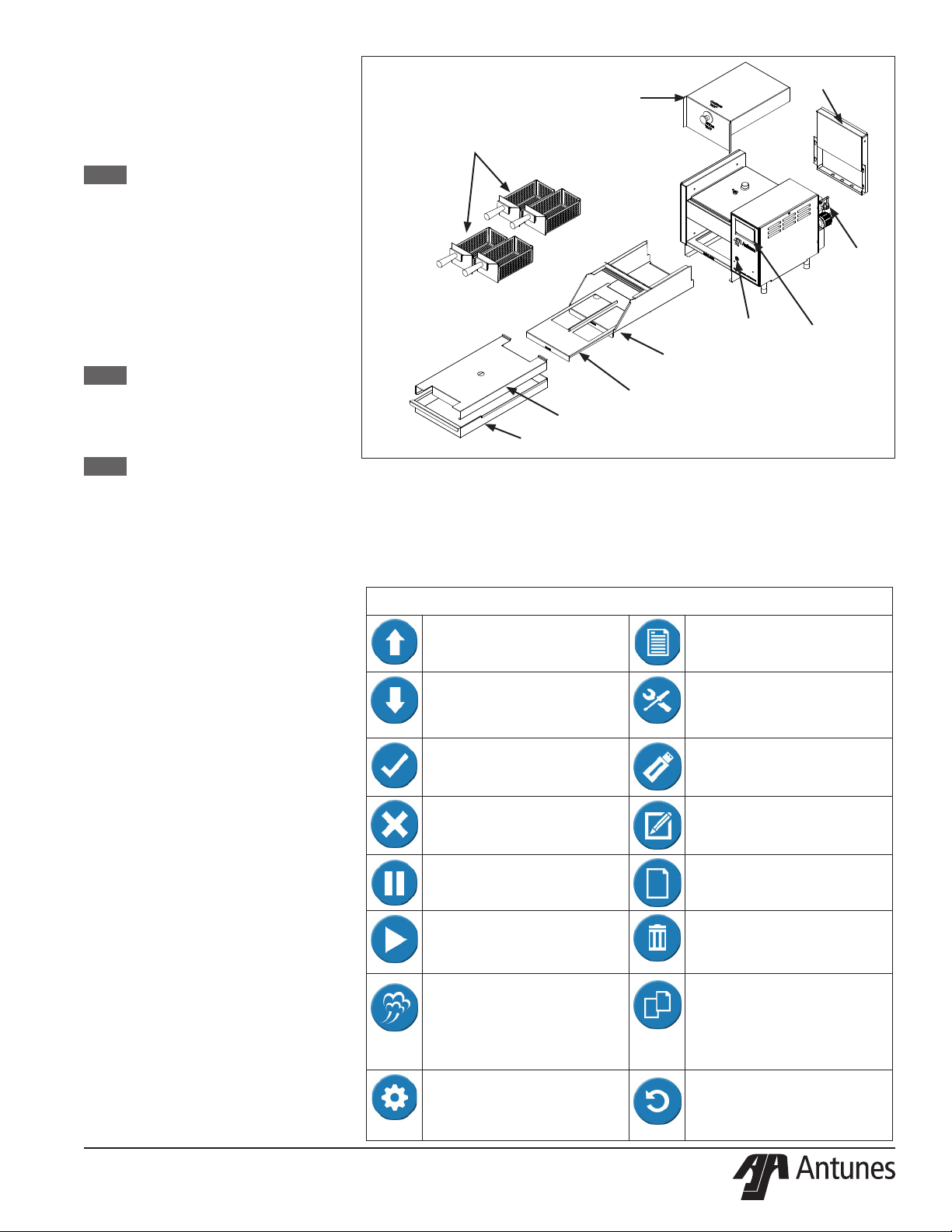
2. Put on heat resistant gloves and
remove the items in Figure 6.
3. Wash, rinse, and sanitize the items
removed at the sink. Allow to air dry.
4. Wipe the exterior of the unit and the
inner part of the basket cavity with a
clean, sanitized towel. Clean up any
spills completely. Allow to air dry.
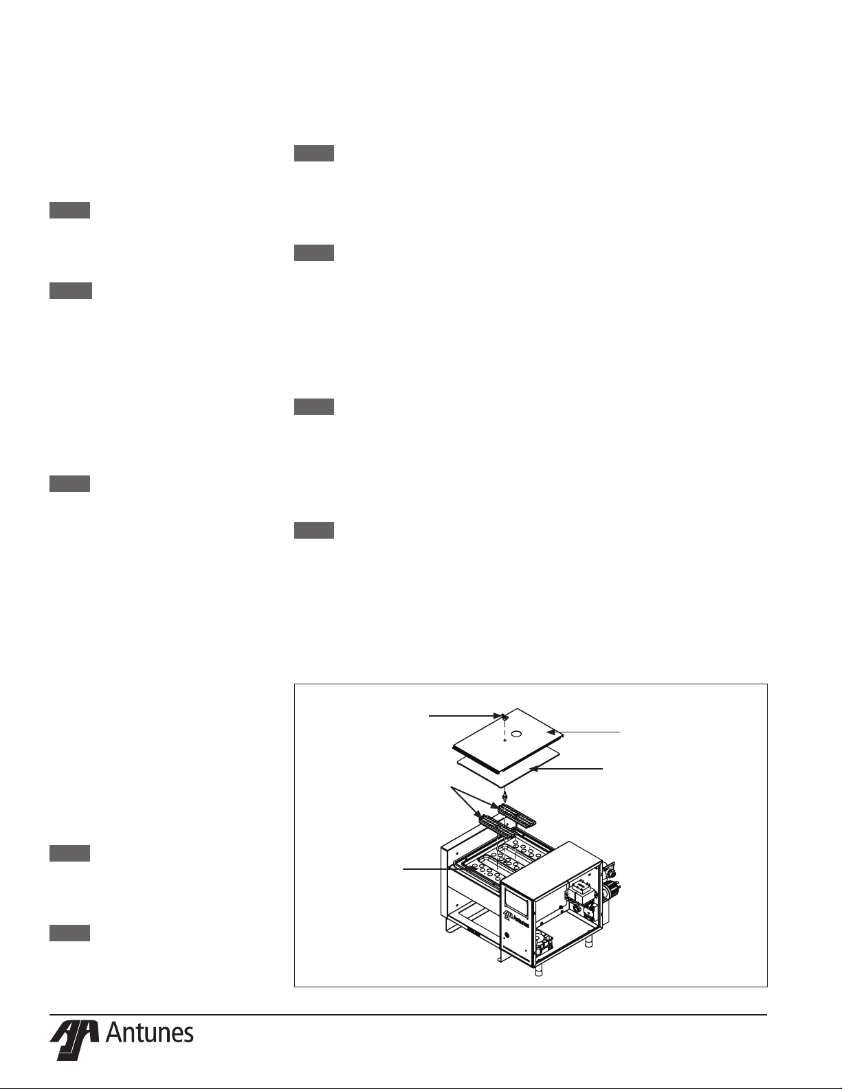
5. Remove wing nut and generator
cover assembly, generator gasket,
and diusers (Figure 7).
6. Examine all steam generator
orices (holes). If mineral deposits
have formed, place a at blade
screwdriver into openings. Use a
twisting motion to scrape openings
clean.
NOTE: Antunes part number 7002129
Kit Cleaning Tool Steamer has
a wire brush, pipe brush, and
a tool designed to clean the
orices in the generator.
NOTE: Mineral deposits come o
in “akes” or in layers if the
build-up is excessive.
7. Use an abrasive cleaning brush and
small scraper to remove deposits
from the generator surface.
8. Pour delimer or vinegar solution (not
supplied) onto the generator surface
and allow to soak for one hour.
NOTE: Be sure to Follow the usage
instructions on the delimer
packet.
9. Remove the delimer solution from
the generator and rinse with clear
water to remove traces of delimer.
NOTE: To ensure proper steaming
characteristics some mineral
deposits must be present on
generator casting.
If during cleaning, the
generator does become free of
mineral deposits, add ordinary
tap water (non reverse
osmosis or ionic lter system)
to casting and allow to boil o.
NOTE: In soft water areas, it may
be necessary to add a small
amount of baking soda to the
generator to “season” it. This
will ensure proper steaming
characteristics by producing a
thin coating of mineral depos-
its on the casting.
NOTE: Seasoning mixture consists
of 3 tablespoons baking soda
and 12 oz. of water. Pour 1/4”
deep of seasoning mixture
into a hot generator. After
mixture is converted to steam,
the remaining loose powder
is removed and generator
cleaned.
Figure 7. Steam Generator
Support Channel
Generator Cover
Assembly
Wing Nut
Diffusers
Steam Generator
10. Wipe the exterior of the unit and the
inner part of the basket cavity with
a clean, sanitized towel. Allow to air
dry.
11. Re-install the diusers, generator
cover, generator cover bracket and
secure with the wing nut.
12. Re-install all items removed in Step
2.
Checking and Cleaning Water
Strainer
To ensure proper and consistent
steaming results, inspect the water ow
regulator and strainer cup regularly.
If the water pressure on the gauge
has dropped, visually check the clear
plastic strainer cup and clean out the
accumulated debris as follows:
1. Shut o the water supply valve to
the unit. Unscrew the clear plastic
strainer cup and carefully remove the
mesh strainer screen.
2. At the sink, gently ush all of the
accumulated debris from the strainer
cup and mesh strainer screen. Be
especially careful not to damage the
mesh strainer screen.
3. Carefully place the mesh strainer
screen into its seat at the bottom of
the clear plastic cup and conrm that
the O-ring is properly seated in its
place before screwing the strainer
cup and top back together.
4. Purge the air out of the strainer
tubing by disconnecting the male
quick disconnect tting from the
equipment and, over a bucket,
pushing its valve core in until there is
a good water ow.