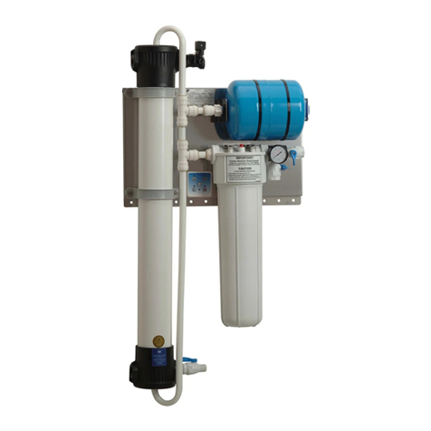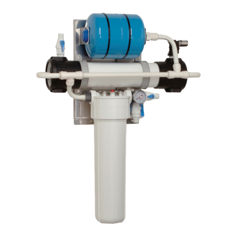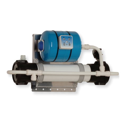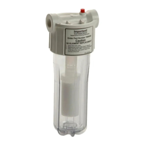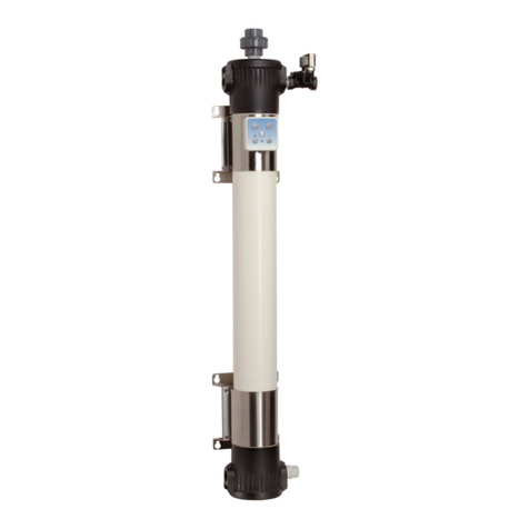
RESIDENTIAL VZN
9
P/N 1011586 Rev A 07/20
Installation
Mounting the System
NOTE: Use caution when lifting and
mounting the system. The
system MUST be mounted
using the provided Mounting
Bracket.
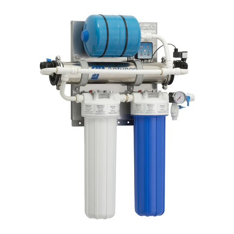
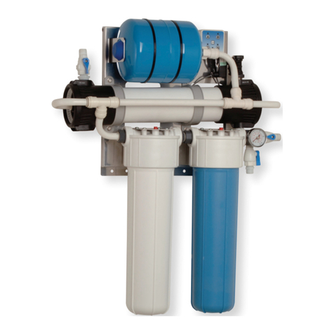
The VZN system comes with a Mounting
Bracket. When mounting the system, pay
attention to the following guidelines:
yAllow sucient access for cartridge
replacement. The VZN-520H
system should be mounted with
23 inches to the left or right of the
system. The VZN-540H system
should be mounted with 43 inches
to the left or right of the system
yMount the system near but
NOT above an appropriate
electrical outlet.
yMount the system near a drain
for ushing operations.
yMount the system before all
consumable water
ltration processes.
ySecure the Mounting Bracket
provided with the VZN system
into wall studs with heavy duty
hardware capable of supporting
120lbs. Or more (Mounting
Hardware Not Supplied).
yMount the VZN system to the
Mounting Bracket and secure with
heavy duty hardware (Mounting
Hardware Not Supplied).
The system is pre-assembled to a Back
Panel. The Back Panel has mounting
holes across the bottom portion to secure
the bottom of the system to the wall.
Some of the bottom mounting holes
may be obscured. Plan your mounting
accordingly.
Follow these steps to secure the
Mounting Bracket to the wall and seat the
VZN system:
1. Use a stud nder and level to attach
the Mounting Bracket securely to the
wall with the appropriate mounting
hardware (Figure 2).
2. The Mounting Bracket is designed
so that the VZN system can be lifted
and hung on the Mounting Bracket.
With assistance, lift the system and
seat it onto the Mounting Bracket
securely (Figure 2).
3. After mounting the VZN system to
the Mounting Bracket, secure the
VZN system to the wall using the
mounting holes provided on the
lower portion of the VZN system
back panel.
Alternative Vertical Mounting
The system can be mounted vertically if
required. See Figure 2A for more details.
Note the following when mounting a
system vertically.
1. Install the Mounting Bracket
horizontally as shown in Figures 2
and 2A.
2. The system must be mounted so the
Solenoid Valve is located at the TOP
(Figure 2A).
3. Allow sucient access for cartridge
replacement. VZN-420 units should
be mounted with 20 inches above
or below. VZN-440 units should be
mounted with 40 inches above or
below.
Figure 2. Mounting the System
A
32
31
31
20
28
36
21
22
23
35
23
22 21
39
39
39
39
39
3239
39
INLET ENDCAP ASSEMBLY
43
DETAIL A
SCALE 1 : 2
SEE DETAIL "B"
FOR INSTALLATION
DETAIL OF ITEMS
21, 22, AND 23
20
28
36
21
22
21
22
23
39
39
NOTE ORIENTATION
OF ITEM 28 PRIOR TO
INSTALLATION INTO
ITEM 20
23 43
B
32 32 31
31
20
21
22
23 34 12
21
22
23
39 39 39
39
39
37 38
39
DRAIN ENDCAP ASSEMBLY
5. INSTALL ITEMS 21, 22, AND 23
INTO PORT 1 OF ITEM 20.
6. INSTALL ITEMS 21, 22, AND 23
INTO PORT 2 OF ITEM 20.
7. ATTACH ITEM34 TO ITEM 12 BEFORE
INSTALLING INTO PORT 1 OF ITEM 20.
43
DETAIL B
SCALE 1 : 2
20
21
22
23
34
21
22
23
39
39
39
ITEM 21 STEP 1:
PRESS O-RING INTO
PLACE AGAINST STEP
ITEM 22 STEP 2:
PRESS O-RING GUIDE WITH
THE BEVEL FACING OUTWARDS
ITEM 23 STEP 3:
SNAP COLLET INTO
PLACE
43
NOTES:
1. ASSEMBLE PARTS AS SHOWN.
2. APPLY PIPE TAPE ITEM 39 AND THREAD SEALING
COMPOUND ITEM 38 TO ALL PIPE THREADS AS NOTED.
3. APPLY LUBRICANT ITEM 40 TO ALL O-RINGS. ENSURE
ALL ARE SUFFICIENTLY GREASED.
4. MAKE SURE END CAPS ITEM 20 (2X) ARE ATTACHED TO
HOUSING ITEM 19 BEFORE ATTACHING HOUSING ASSEMBLY
ITEM 19 TO BACK PLATE ITEM 1.
C1
C2
D1
REV
DATE
PCO NO.
DESCRIPTION
BY
D
06/11/20
PC-14371
D1 ADD ITEM 43 & D2 ADD NOTES
RC
C
11/25/19
PC-14371
C1 WAS 3250103; C2 QUANTITY WAS 4 EA
RC
ITEM
PART NO
DESCRIPTION
QTY.
1 0509346
BACKPLATE, VZN 520/540, HORIZ
1
22180215
TANK-EXPANSION, 2.1 GAL WITH 3/4 NPT
1
30400381
GROMMET, 1.75OD X 1.187 ID
1
42190158
FEMALE CONNECTOR, 3/4 CTS X 3/4 NPS
1
50012357
UNIVERSAL PULSE CONTROLLER ASSY
1
62010199
TUBING, BENT, 90 DEGREE
1
72180287 CLAMP, UFL HOUSING 2
8 3000116
NUT RETAINER - 1/4"-20
4
9 3250195
SCREW, HEX CAP 1/4-20 X 7/8"
4
10 3250154
WASHER, Ø1/4" HELICAL SPRING LOCK
4
11 3250104
WASHER, FLAT - 1/4"
4
12 4040189
VALVE, SOL NC, 24VDC, 3/4 NPT
1
13 2010247 TUBING, PEX-B, 3/4" CTS, 180°, 4.53" X 3.843 2
14 2190155
UNION TEE, 3/4" CTS
2
15 2010246
TUBING, PEX-B, 3/4" CTS, 19.72" STRAIGHT
1
16 4060438
CABLE TIE 36" BLACK
2
17 2120286
SPACER, RUBBER, 4" SS UF HOUSING
2
18 3000132
NUT, CAGE, 8-32, ZP STEEL
2
19 0508910
HOUSING, 4 DIA x 20"L, SS 304, UF
1
20 2180560 CAP, NORYL, 3/4 PEX X 3/4 PEX, 4" DIA SS HSG 2
21 0200283
O-RING, 21MM ID X 4MM W, EPDM 70, RND
4
22 2180278
O-RING GUIDE, 3/4" CTS
4
23 2180279
COLLET, 3/4" CTS
4
24 8000057
BOLT, M8x1.25x35mm, HEX, 18-8 SS
4
25 8000059
WASHER, FLAT, M8, 8.4 ID x 16 OD x 1.6 D
4
26 8000058
NUT, M8 x 1.25 x 6.5mm, 18-8 SS
4
27 2120285
SPACER, 5/8 OD X 3/8 ID X 1/2 D
4
28 2170140
REGULATOR, FLOW 7.9 GPM
1
29 2110217
CLAMP, 304 SS, 4" SS UF HOUSING ENDCAP
4
30 3080120
SCREW, MACH. #8-32 x 5/8"
2
31 0200432
O-RING, AS568 2-342, EPDM 70
4
32 0200236
O-RING, CARTRIDGE
4
33 0700769
WIRE HARNESS, GAP-421 VALVE
1
34 2190210
FITTING, 3/4 MPT X 3/4 CTS STEM, JG
2
35 2170173
VALVE, BALL, 3/4 CTS X 3/4 FPT, BLACK, PLASTIC
1
36 2180575
BUSHING, PVC, .906 OD X .656 ID X .218 L
1
37 2140163 THREAD SEALING COMPOUND, (RECTORSEAL) 1
38 2140144
TAPE, PIPE THREAD
1
39 2140153
LUBRICANT, DOW CORNING, HIGH-VACUUM GREASE
1
40 4060173
CABLE TIE(.100x4-3/16)
1
41 1200168
ASSY/TEST PROCEDURE GAP
1
42 0200476
GASKET, VZN-5XX UF HSG, CLAMP BRACKET
2
43 2190304
COLLET CLIP, 3/4 CTS
4
D
C
B
A
B
C
D
1
2
3
4
5
6
7
8
8
7
6
5
4
3
2
1
E
F
E
F
A
ALL DIMENSIONS: INCH [mm]
TOLERANCES:
FRACTIONS
1/32" [.8mm]
DECIMAL
.xx
.01" [.25mm]
.xxx
.005" [.125mm]
ANGULAR:
1
MATERIAL SPECIFICATION:
DRAWN BY:
DATE:
PART DESCRIPTION:
SIZE:
C
PART NUMBER:
REV:
SHEET 1 OF 2
1:4
UNLESS OTHERWISE SPECIFIED:
8/1/2018
RDB
0013992
SEE BOM
MAIN ASSY, VZN 520H
D
THE INFORMATION AND DESIGNS CONTAINED IN THIS DRAWING ARE CONFIDENTIAL AND THE
PROPRIETARY PROPERTY OF A.J. ANTUNES & CO. NEITHER THIS DESIGN NOR ANY INFORMATION
CONTAINED HEREIN MAY BE REPRODUCED OR DISCLOSED TO OTHERS WITHOUT THE EXPRESS
WRITTEN CONSENT OF A.J. ANTUNES & CO.
SCALE:
DATE:
APVD BY:
INTERPRET DIMENSIONS AND
TOLERANCES PER ASME Y14.5-2009
NO BURRS ALLOWED
BREAK ALL SHARP CORNERS
THIRD ANGLE
PROJECTION
DO NOT
SCALE
DRAWING
180 KEHOE BLVD, CAROL STREAM, IL 60188
ISO COMPLIANT COMPANY
Back Plate
(holes along bottom for
additional mounting stability)
Back Plate
(holes along right
for additional
mounting stability)
Solenoid Valve
at Top
Mounting
Holes
Secure Mounting Bracket
to wall studs using
appropriate hardware.
The system is
designed to hang
from the Mounting
Bracket.
The system is
designed to hang
from the Mounting
Bracket.
Secure Mounting
Bracket to wall studs
using appropriate
hardware.
Caution
Due to its weight and size, the
VZN system MUST be mounted
with the provided Mounting
Bracket. Read the Mounting
the System section before
attempting to mount the VZN
system. Use care when lifting
heavy objects.
4. With assistance, lift the system and
seat it securely onto the Mounting
Bracket vertically (Figure 2A).
5. When mounted vertically, the back
plate has mounting holes across the
right portion to secure the right side
of the system to the wall.
Figure 2A. Vertical Mounting
