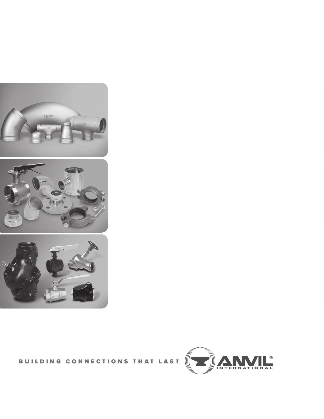
1007 & 3007 ROLL GROOVER
4
SAFTETY INSTRUCTIONS
A. GENERAL
1. Carefully read and understand these operating instructions
before assembling and operating the Groover.
2. Read and follow the safety labels on the Groover.
3. Understand the function and the location of all power and
grooving controls before using the Groover.
B. OPERATOR SAFETY
1. Do not wear loose clothing, loose sleeve cuffs, loose
fitting gloves, or jewelry that could get caught in moving
parts.
2. Wear safety glasses and safety shoes.
3. Tie-up or cover long hair.
4. Wear ear protection if using the Groover in a high noise
area or for prolonged periods of grooving.
5. Do not operate the Groover if you are tired from fatigue
or medication.
6. Do not allow horseplay around the Groover.
C. GROOVER SET-UP
1. Provide a safe work area. Keep the work area well lighted
and maintain a clear, uncluttered space for operation of the
Groover.
2. Do not use the Groover in wet or damp locations.
The floor area around the Groover must be dry and free
of slippery materials.
3. Set-up the Groover on firm, level ground. Do not locate the
Groover on sloped or irregular ground conditions.
4. Remove all tools, wrenches, etc., from the Groover and
power drive base before applying power to the Groover.
5. Do not attempt to lift the Groover by yourself. A hoist
is recommended for lifting and moving the Groover.
6. Use the Model 3007 Groover only with a Ridgid*300 Power
Drive with 38 RPM operation.
7. The Model 3007 Groover must be properly mounted on the
Ridgid 300 support arms and the Groover driveshaft firmly
tightened Into the Ridgid 300 chuck jaws.
8. Unplug the Ridgid 300 drive power cord on the Model
3007Groover or switch the drive power switch to the "Off"
position and lockout the switch with a padlock on the Model
1007 Groover prior to servicing or changing groover parts.
9. Tool and Ridgid 300 Power Drive must be mounted to the
floor for proper operation.
THE GRUVLOK®MODEL 1007 AND 3007 ROLL GROOVERS ARE TO BE USED ONLY FOR ROLL GROOVING OF PIPE.
These operating instructions provide important information for the safe operation of the Groovers to protect the operator
from possible, serious injury. The Groovers are designed for safe, reliable operation. However, unforeseen circumstances,
impossible to predict, could result in an accident. Following the information in these operating instructions will permit safe
operation of the Groover.
D. GROOVER OPERATION
1. All safety guards must be in place. Never operate the Groover
with the guards removed.
2. Do not operate the Groover without a foot switch. A foot switch
is required for safe operation of the Groover.
3. Operate the Groover only from the pump side of the Groover.
4. Keep hands away from guide and grooving rolls. The Groover
is designed for "hands clear" grooving.
5. Maintain balanced footing keeping the foot switch within comfortable
reach. Do not reach across the Groover or pipe. Keep hands and
clothing away from all moving parts.
6. Do not place excessive force on the hydraulic pump handle.
Follow grooving instructions for safe Groover operation.
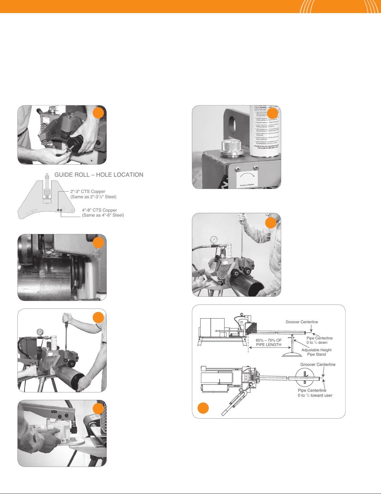
7. Provide proper pipe support with a pipe stand fastened to the
floor or ground.
8. Use the Groover only for the size and wall thickness pipe for which
it was designed.
9. Do not operate the Groover if any part of the Groover is damaged
or broken.
10. Do not attempt to groove pipe shorter than 5" in length.
11. Keep all visitors and bystanders at a safe distance from the
Groover, pipe and power cords.
E. ELECTRICAL SAFETY
1. Ground the Ridgid 300 Power Drive (Model 3007) or drive motor
(Model 1007). The power drive must be connected to aninternally
grounded electrical system.
2. The Model 1007 Groover must be connected to the proper power
supply that matches the Groover either a 115 volt, 60Hz, single
phase power supply with 30 amp capacity.
3. Use 3-wire extension cords only which have 3-prong grounding plugs
and 3-pole receptacles which mate with the Groover's plug.
4. Extension cord conductor size (i.e. American Wire Gage) must be large
enough to prevent significant voltage drop which could damage the
Groover drive motor or cause loss of power. The chart below shows the
recommended extension cord size.
EXTENSION CORD LENGTH** REQUIRED WIRE SIZE
25' 12
50' 12
100' 10
**Extension cord length greater than 100 Feet is not recommended.
*“RIDGID” is a registered trade mark of Emerson Electric Company.
CAUTION