Anyload 805BS-TN-B User manual

805TS
&
805BS Series
General Purpose Digital Weight Indicators
Operations Manual (v1703)
805TS-B-17
805BS-B-17
805BS-TN-B
(Lite Version)

TABLE OF CONTENTS
1. Introduction 3
2. Safety Recommendations 4
3. Operation Modes 5
4. Front Panel Keypad 6
5. Indicating Lights 7
6. Start Up 8
7. Operations 8
7.1 Normal Weighing Mode 8
7.1.1 Gross/Net Mode 9
7.1.2 Units 9
7.1.3 Zero Scale 9
7.1.4 Acquire Tare 9
7.1.5 Remove Stored Tare Value 9
7.1.6 Print 9
7.2 Peak Mode Operations 10
7.2.1 Units 10
7.2.2 Peak/Normal Weighing Mode 10
7.2.3 Remove Peak Mode Value 11
7.2.4 Zero Scale 11
7.2.5 Print 11
7.3 Count Mode Operations 11
7.3.1 Gross/Net Mode 12
7.3.2 Units 12
7.3.3 Zero Scale 12
7.3.4 Acquire Tare 12
7.3.5 Remove Stored Tare Value 12
7.3.6 Input Item Code 12
7.3.7 Printing in Count Mode 13
7.3.8 Fast Setup of Count Items Average Weight 13
8. Wire Installation 14
8.1 DC power supply 15
8.2 SW2 Switch 15
8.3 KOUT: Relay signal outputs 15
8.4 SW3: Output: RS485/COM 15
8.5 SW4: Output: USB/RS232 15
8.6 Load Cell Input 15
8.7 COMM: Serial Communication port 16
8.8 Printers 16
9. Configurations 16
1 | ANYLOAD 805TS & 805BS Series Weighing Indicator Operations Manual (v1703)

9.1 Front Panel Configurations 17
9.2 Menu Structure and Parameters Descriptions 18
9.2.1 F1(Configuration) Menu 20
9.2.2 F2(Format) Menu 23
9.2.3 F3(Calibration) Menu 26
9.2.4 F4(Serial) Menu 27
9.2.5 F5(Mode) Menu 29
9.2.6 F6(Relay) Menu 30
9.2.7 F7(Ver) Menu 32
9.2.8 F8(PFormat) Menu 33
10. Calibration 33
11. Count Items Average Weight Setup 37
12. Relay Output Setup 39
13. Print Format 41
13.1 Print Format Commands 42
13.2 GFMT and NFMT Print Format Input 43
13.3 Default Formatting 44
13.4 Print Consecutive Number 45
13.5 Date and Time Settings 46
14. Serial Communication 47
14.1 Continuous Transmission 47
14.2 Transmission Upon Request 48
14.2.1 Data Transmission Sequence 49
14.2.2 Communication Command 50
14.3 Serial Communication Test 51
15. Appendices 52
15.1Error Messages 52
15.2 Software Version and Default Configuration Parameters 53
15.2.1 Find out indicator software version 53
15.2.2 Restore Factory Setup Parameters 53
15.2.3 Enabling Password Function 54
15.2.4 Basic Configurations of Indicator 55
15.3 Technical Specifications 56
15.4 ASCII Codes Table 57
15.5 Indicator Display Characters 58
2 | ANYLOAD 805TS & 805BS Series Weighing Indicator Operations Manual (v1703)

1. Introduction and Product Features
Thank you for choosing Anyload General Purpose Digital Weight Indicators. The
805TS and 805BS series indicators are general purpose indicators that provide
high accuracy and reliability with multiple functions. These indicators have an
A/D adopted conversion technology of a 24-bit resolution with a rate of
conversion of up to 960 cycles per second and drives up to eight 350Ω or
sixteen 700Ω load cells. With a SS304 stainless steel wash down enclosure, the
805TS and 805BS are ideal for food industry, agricultural industry, and industrial
applications. These indicators are NTEP III/IIIL, 10000 and Measurement Canada
III, 10000; III HD 20000 approved.
Key Features:
805TS
805BS Series
Parameter settings and calibration procedures are performed at the front panel
Auto zero scale can be selected when switching on indicator
Auto zero tracking
Unit exchange between kg & lb
Unit Selection: kg, lb, g, oz, lb:oz
0.8 in (20mm) in height red LED
display and with option for blue LED
143mm x 41mm LCD white
background and blue font display, and
with option for blue background and
white font
Improper operation and fault indication
Normal Weighing mode, Peak mode and Count mode functions
2 way relay signal output ( not available in 805BS-TN-B Lite Version )
Zero Scale, Tare mode, Gross/Net weight selections
Equipped with RS232C and RS485 connecting port with options for Data
Transmitted Continuously and Data Transmitted Upon Request
Print functions with programmable print format (with build-in clock to show
dates and hours
Can drive up to eight 350Ω or sixteen 700Ω load cells through a junction box
This manual provides installation, operation and configuration information of
indicator models 805TS and 805BS series. It is recommended to go through the
manual in details before installing, operating or configuring the indicator.
3 | ANYLOAD 805TS & 805BS Series Weighing Indicator Operations Manual (v1703)

4 | ANYLOAD 805TS & 805BS Series Weighing Indicator Operations Manual (v1703)
Checking What is in the Box:
805TS or 805BS indicator Operations Manual
2. Safety Recommendations
Important instructions,which involve safety,are highlighted with the
appropriate mark:
When it is required to work inside the indicator enclosure for some
procedures described, the work can only be performed by qualified technical
personnel.
When using the equipment in surroundings with increased
safety requirements, the corresponding regulations must be
observed:
The indicator may only be used with the power adapter supplied
exclusively for use with the device.
Before inserting the power adapter, the user must ensure that
the operating voltage stated on the power adapter agrees with
the mains voltage.
If not, please contact Anyload Customer Service.
Power Adapter for 805TS & 805BS
series

If the power adapter or its cable is damaged,the
indicator must immediately be disconnected from the
electricity supply (pull out the power adapter).
These operating instructions must be read by each operator of the equipment
and must be available at the workplace at all times.
3. Operation Modes
Weighing Mode
When SW2 switch is switched to off, indicators are in the weighing mode for
805TS and 805BS Series. Refer to Section 8 on switching configurations and
weighing mode.
In F5.1 Menu, three different Weighing modes can be selected (refer to F5.1
Menu):
(1)Normal Weighing mode: Indicator displays gross weight or net
weight in this mode. Unit of the displayed weight is highlighted by
indicator light and different units can be toggled (refer to Section7.1).
(2)Peak mode: Indicator displays peak value of load acted upon the
weighing instrument (refer to Section 7.2).
(3)Count mode: Indicator displays number of weighed items having the
same weight (refer to Section 7.3).
Configurations Mode
When SW2 switch is switched to on, indicators are in the configurations mode.
Refer to Section 8 on switching configurations and weighing mode.
Most of the operation data settings including parameters setting and weighing
range calibration are to be carried out in Configurations mode.
Remove the back panel of indicator (refer to Fig 8.1 Sockets on Circuit Board).
Switch on SW2 jumper located at the lower corner. Indicator will be in
Configurations mode and display shows “F1”. Refer to Section 9 for details.
5 | ANYLOAD 805TS & 805BS Series Weighing Indicator Operations Manual (v1703)

6 | ANYLOAD 805TS & 805BS Series Weighing Indicator Operations Manual (v1703)
4. Front Panel Keypad
Fig. 4.1 Front Panel Configuration for 805TS
Fig. 4.2 Front Panel Configuration for 805BS series
Fig.4.1 and Fig.4.2 shows indicator display, LED/LCD indicator lights and keypad
configuration. Signs at the bottom of the keypad are for configuration operation
use (refer to Section 9 for details).
The signs are for inputting item codes in Count Mode (refer to section 7.3 for
details).

5. Indicating Lights and Symbols
Indicating Lights for 805TS
Indicating Symbols for 805BS Series
“Peak”—— Light is on when
operating in Peak mode
“ ”——Peak, The symbol is
displayed when operating in Peak mode
“Count”—— Light is on when
operating in Count mode
“ ”——Count, The symbol is
displayed when operating in Count
mode
“kg”—— Light is on when display
showing units in kg.
kg”—— The symbol is displayed when
display showing units in kg.
“lb”—— Light is on when display
showing units in lb.
“lb”—— The symbol is displayed when
display showing units in lb.
N/A “g”—— The symbol is displayed when
display showing units in g
N/A “oz”—— The symbol is displayed when
display showing units in oz
N/A “lb:oz”—— The symbol is displayed
when display showing units in lb:oz.
“Gross”—— Light is on when display
showing gross weight
“ ”—— Gross, The symbol is
displayed when display showing gross
weight.
“Stable”—— Light is on when load is
stable or within the preset dynamic
load range (refer to F1.4 Menu for
dynamic load setting).
“ ”—— Stable, The symbol is
displayed when load is stable or within
the preset dynamic load range (refer to
F1.4 Menu for dynamic load setting).
“Zero”—— Light is on when load is
within zero range (<1/4d).
“ ”—— Zero, The symbol is
displayed when load is within zero
range (<1/4d).
“Tare”—— Light is on when Tare
setting is not zero
“ ”—— Tare, The symbol is
displayed when Tare setting is not zero
7 | ANYLOAD 805TS & 805BS Series Weighing Indicator Operations Manual (v1703)

6. Start up
Connect power supply. For the 805TS, the indicator automatically goes through
a self checking process (showing all 0 to all 9, decimal point and indicator lights).
For the 805BS series, pressing on the ON/OFF button on the front panel for 2
seconds to turn on the power. Once on, the indicator will proceed with the self
checking process. There are two possible outcomes depending on F1.8 and F1.9
Menu settings:
oWhen indicator is set to Auto Zero and Manual Zero (F1.8=0 and
F1.9=0, respectively and the load on the scale is within the zero scale
setting in F1.3 Menu, the indicator zeros automatically or manually and
display shows “0”.
oOtherwise if F1.8=1 & F1.9=1, the indicator is set not to Auto
Zero/Manual Zero. If the load exceeds the zero scale setting in F1.3
Menu, display shows actual load.
Refer to F1.3 Menu along with the F1.8 & F1.9 Menu for further information.
7. Operations
The indicator goes to Weighing mode when the SW2 switch is turned off. Under
the Normal Weighing mode, the Peak mode and Count mode can be set at F5.1
Configurations Menu (refer to F5.1 Menu).
7.1 Normal Weighing Mode
When the indicator is set to Normal Weighing Mode, the parameter value in
F5.1 should be F5.1=0 (refer to F5.1 Menu).
For 805TS (F5.1=0), the “Peak” light and “Count” light are off. Indicator is in
Normal Weighing mode.
For the 805BS series(F5.1=0), both “Peak” and “Count” symbols won’t appear in
the display. Indicator is in Normal Weighing mode.
Basic operations in Normal Weighing mode:
7.1.1 Gross/Net Mode
8 | ANYLOAD 805TS & 805BS Series Weighing Indicator Operations Manual (v1703)

Press 【GR/NET】, change to Net weight from Gross weight or vice versa.
When tare weight is stored (indicator has stored tare weight value other than 0),
Net weight shown on the display is equal to Gross weight minus the Tare weight.
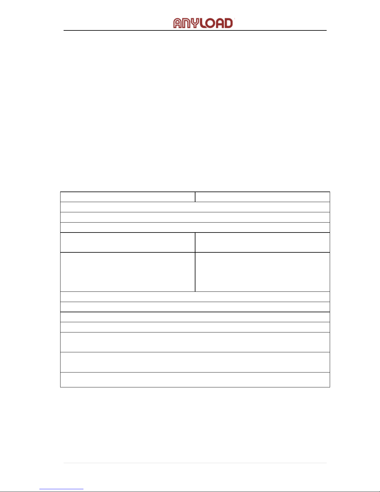
For the 805TS series, the ”Gross” light is on when indicating gross weight and
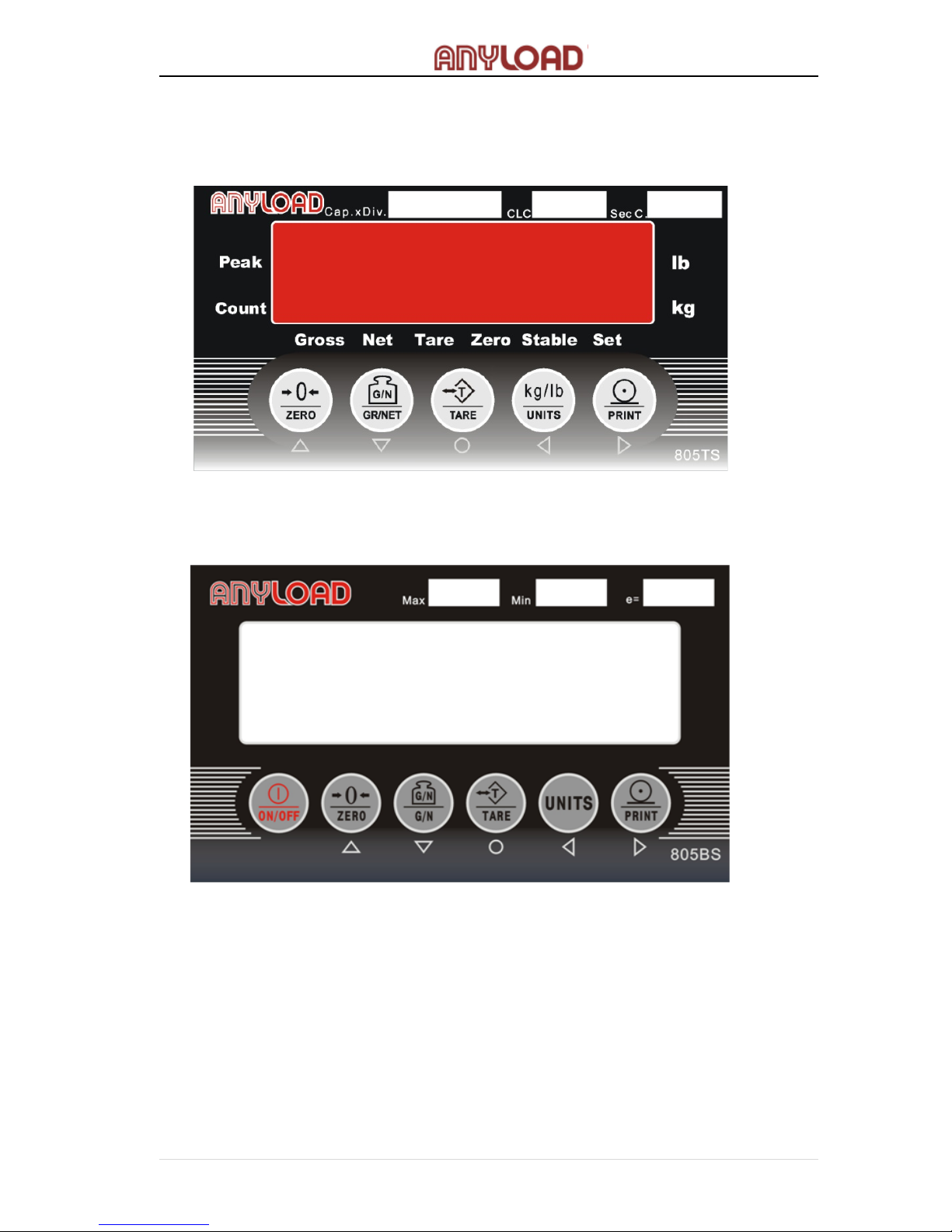
the ”Net” light is on when indicating net weight while the 805BS series,
the ”Gross” symbol is displayed when indicating gross weight and “Net” symbol
is displayed when indicating net weight.
7.1.2 Units
When parameter in F6.1 menu is set to OIML or NONE mode, press the【UNITS】
button in changing units. But if F6.1 is set to NTEP or CANADA, the unit toggling
is not allowed. For 805TS series, the corresponding lights on the far right side of
the screen indicate which unit type is currently set while for 805BS series, the
unit symbol appears in the display like Kg, lb or Oz.
7.1.3 Zero Scale
When in Gross mode (“Gross” light is on for 805TS series, or for the 805BS
series, “Gross” symbol is displayed), remove the load from scale and wait until
the “Stable” indication is present. Press 【ZERO】and the “Zero” light will turn
on (805TS series) or the “Zero” symbol will be displayed (805BS series). This
indicates that the Zero Scale setting is complete
7.1.4 Acquire Tare
When no Tare is stored (“Tare” light is off), place the container on the scale and
wait until the “Stable” indication is present. Press 【TARE】, this will store the
Tare weight. If “Net” light is on (805TS series) or the “Net” symbol is present
(805BS series), the display shows the Net weight (refer to F6.1 Menu).
7.1.5 Remove Stored Tare Value
When a tare weight is stored (“Tare” light is on or “Tare” symbol is displayed),
press 【TARE】to remove the stored tare value. The display will show the
Gross weight while the “Gross” light (805TS series) is on or the “Gross” symbol
is displayed (805BS series)(refer to F6.1 Menu).
7.1.6 Print
Ensure that the “Stable” indication is on, then press 【PRINT】. Data from
indicator is then transmitted to a serial printer for printing. After each printing,
9 | ANYLOAD 805TS & 805BS Series Weighing Indicator Operations Manual (v1703)

the Consecutive Number is increased by 1. The print format is set according to
F8 Menu (refer to Section 13 for Print Format).
7.2 Peak Mode Operations
Only when F6.1 Menu is set to None mode, the F5.1 Menu can be set to Peak
Mode. If F5.1=1, the “Peak” light will turn on (805TS series), or the “Peak”
symbol will appear (805BS series) and the indicator will be in Peak mode (refer
to F5.1 Menu setting).
When in Peak mode, the display shows gross weight. Press the【GR/NET】
button to switch between Peak and Normal Weighing modes. Press the 【TARE】
button to cancel Peak mode.
Basic operations in Peak mode include:
7.2.1 Units
When Peak mode operation is deactivated (“Set” light is off for 805TS and “Set”
symbol is not displayed for 805BS), pressing the 【UNITS】button will display
the available units like kg, lb, or oz. Corresponding unit indicating the light is on
for 805TS while indicating symbol is displayed for 805BS
When Peak mode operation is activated (“Set” light is on for 805TS and “Set”
symbol is displayed for 805BS)), the 【UNITS】button does not function to
show available units.
7.2.2 Peak/Normal Weighing Mode
When “Set” light is on (805TS) or “Set” symbol is displayed (805BS), the Peak
mode is activated. The display shows the maximum value of load which has
been applied to the load cell. When the load is removed, the display still shows
the peak load.
Pressing 【GR/NET】can change indicator from Peak mode to Normal
Weighing mode, or vice versa
When “Set” light is off (805TS) or “Set” symbol is not displayed (805BS), Peak
mode is deactivated. The value shown on the display changes according to the
load applied to the load cell.
10 | ANYLOAD 805TS & 805BS Series Weighing Indicator Operations Manual (v1703)

7.2.3 Remove Peak Mode Value
During the Peak mode, remove the load and press 【TARE】button, the current
Peak mode value will be reset and the indicator will start for another Peak
mode operation.
7.2.4 Zero Scale
During the Peak mode,pressing the 【GR/NET】button will switch the indicator
to Normal Weighing mode or vice versa.
Remove the load and when the “Stable” indication is present, press 【ZERO】.
The display will show the zero value.
7.2.5 Print
When Peak mode is on (“Set” light is on or symbol is displayed), pressing the
【PRINT】button will print the Peak value. When the Peak mode is off (“Set”
light is off or symbol is not displayed), pressing the 【PRINT】button will print
the current load value. After each printing, the Consecutive Number is
increased by 1. The Print format can be set at F8 Menu (refer to Section 13 for
Print Format). To print Peak value, ensure that it has been set up properly in the
Print format settings.
7.3 Count Mode Operations
Only when F6.1 Menu is set to None mode, F5.1 Menu can be set to Count
mode. If F5.1=2 the indicator will turn to Count Mode- “Count” light is on for
805TS series or “Count” symbol is displayed for 805BS series. The indicator will
now perform Count mode operations (refer to F5.1 Menu).
Basic operations in Count mode:
7.3.1 Gross/Net Mode
Pressing the【GR/NET】button will switch between Gross and Net weight
mode. When in Tare mode, Net weight is equal to Gross weight minus Tare
weight. The “Gross” light is on (805TS series) or the “Gross” symbol is displayed
(805BS series) when in Gross mode and the “Net” light is on (805TS series) or
the “Net” symbol is displayed (805BS series) when in Net mode.
11 | ANYLOAD 805TS & 805BS Series Weighing Indicator Operations Manual (v1703)

7.3.2 Units
Pressing the【UNITS】button will switch between the weight of load and the
quantity of count items. When showing the weight of load, follow F2.3 Menu to
choose the unit (refer to F2.3 Menu). When showing the quantity of count
items, the display shows “nxxxxx”. xxxxx is the quantity of count items.
7.3.3 Zero Scale
When in Gross mode (for 805TS series, the “Gross” light is on; for 805BS series
the “Gross” symbol is displayed), remove the load from scale. After the “Stable”
light is on (805TS series), or the “Stable” symbol is displayed (805BS series),
pressing the 【ZERO】button the “Zero” light or symbol will be on. The Zero
Scale setting is now complete.
7.3.4 Acquire Tare
When no Tare is stored (“Tare” light or symbol is off), place the container onto
the scale and wait until the “Stable” light is on (805TS series), or “Stable”
symbol is displayed (805BS series). Press 【TARE】and Tare value (weight of
container) is stored. The display will show the Net weight and the “Net” light
(805TS series) will be on, or the “Net” symbol will be displayed (805BS series)
(refer to F6.1 Menu).
Note: Only when the tare value displayed is less than 6 digits the tare value
can be successfully stored, otherwise, the tare option will not activate.
7.3.5 Remove Stored Tare Value
When a tare value is stored (for the 805TS series, the “Tare” light is on; for the
805BS series, the “Tare” symbol is displayed), press 【TARE】to remove the
stored value. The display will show the Gross weight and the “Gross” light
(805TS series) will be on, or the “Gross” symbol (805BS series) will be displayed
(refer F6.1 Menu).
7.3.6 Input Item Code
When in Count Mode, press 【PRINT】to go to Input Item Code status. Display
shows “P= xx”, where xx is the code number of the current count item and x
flashes. Now the functions of the keypad become , , , , .
12 | ANYLOAD 805TS & 805BS Series Weighing Indicator Operations Manual (v1703)

,are for moving forward and backward while ,are for
increasing and decreasing the digits. After done with Input Item Code, press the
key if the stored Item Code is not 0. Item Code of the current count items is
then stored and the keypad returns to normal operating functions as shown in
Fig. 4.1 (805TS series) and Fig.4.2 (805BS series).
If the stored Item Code =00, display goes to the Fast Setup of the Averaging
Weight of the Count Item (refer to Section 7.3.8).
7.3.7 Printing in Count Mode
If the display is showing the weight of the load, the 【PRINT】key is reserved
for entering the count code settings. If the display is showing the quantity of
count items, the 【PRINT】key will print either the GFMT or NFMT text
depending if the indicator is in Gross or Net mode.
7.3.8 Fast Setup of Count Items Average Weight
To obtain the average weight of a count item without going into the
Configuration mode, follow these procedures below:
(1) Enter the Input Item Code according in Section 7.3.6. Set the Item
Code =00. Display shows “P = 00”.
(2) Remove all weights from the scale. Press to zero the scale.
Display shows “CAL” while calibration is in progress.
(3)
After zeroing the scale, display proceeds to Count Items Average
Weight Setup. Use , to select the suitable sample quantity.
Select a larger quantity for lighter count items.
(4) After selecting a suitable quantity and placing the respective quantity
of count items on the scale ,press , the display shows “CAL” while
calibration is in progress. When complete, there are two possible
outcomes:
Display shows “- - E5 - -” when the average weight of the count
items is too small then there are two options:
- Combine a few count items to become one count item. Place
the same quantity of count items to the scale as per the
13 | ANYLOAD 805TS & 805BS Series Weighing Indicator Operations Manual (v1703)

Note: In this procedure, the settings for count items average weight will be
erased once the indicator is switched to other mode or the indicator is
restarted. If you want to save a count items average weight settings
refer to section Section 11.
8. Wire Installation.
Fig. 8.1 Sockets on Circuit Board for 805TS & 805BS series
Note: When connect to 4-wire load cell, please turn SW1 ON.
When connect to 6-wire load cell, please turn SW1 OFF.
SW3 SW4
14 | ANYLOAD 805TS & 805BS Series Weighing Indicator Operations Manual (v1703)
sample quantity set in (3) above. Press to calculate the
average weight.
- Press to cancel Count Items Average Weight Setup and
return to the Weighing mode.
Display shows the count items average weight and returns to the
Weighing mode.
(5) On the Weighing mode, keypad functions are according in Fig.4.1
(805TS and Fig.4.2 (805BS series).

8.1 Power supply
805TS-B-17
Input : 120VAC, 60Hz, 110mA
Output : 9VDC 600mA
805BS-B-17 & 805BS-TN-B
Input : 120VAC, 60Hz, 110mA
Output : 12VDC 400mA
8.2 SW2 Switch
The SW2 switch is used to switch between calibration and normal weighing
mode. When it is turned ON the indicator is in calibration mode, otherwise it
is in normal weighing mode.
8.3 KOUT: Relay signal outputs
Relay Output of 805TS-B-17 & 805BS-B-17
8.4 SW3: Output: RS485/COM
SW3 switch is used to switch between output RS485 and COM mode. When
RS485 output mode is turned ON (left), the RS485 output mode is activated;
otherwise the COM output mode is activated.
Note: Only 805TS-B-17 & 805BS-B-17 have this option ( not equipped in 805BS-TN-B ).
8.5 SW4: Output: USB/RS232
SW4 switch is used to switch between output USB and RS232 mode. When USB
output mode is turned ON (left), the USB output mode is activated; otherwise
the RS232 output mode is activated.
1 2 3 4
15 | ANYLOAD 805TS & 805BS Series Weighing Indicator Operations Manual (v1703)

8.6 Load Cell Input
805TS-B-17, 805BS-B-17 & 805BS-TN-B
1
(
E-
)
— Excitation-
2(FB-)— Sense-
3(S-)— Signal-
4(GND)— Signal ground
5(S+)— Signal+
6(FB+)— Sense+
7
(
E+
)
— Excitation
8.7 COMM: Serial Communication port
805TS-B-17, 805BS-B-17 & 805BS-TN-B
1 (485-) — RS485-
2 (485+) — RS485+
3(1GND)— Signal ground (connect to computer)
4(1RXD)— RS232C Receipt port 1
5(1TXD)— RS232C Output port 1
6(2GND)— Signal ground (connect to computer)
7(2RXD)— RS232C Receipt port 2 (Printer)
8(2TXD)— RS232C Output port 2 (Printer)
Note: RS485 is not available in 805BS-TN-B
8.8 Printers
When hooking up a printer to the indicators 805TS & 805BS series use
connections 2GND, 2RXD, and 2TXD shown in Fig.8.1. To ensure the indicator is
able to print on command set the serial mode (F4.3) equal to comm (1).
9. Configurations
Configure the indicator in the following steps:
Remove the back panel of indicator.
Turn on the SW2 switch.
Indicator will now be in Configuration mode and display shows “F1” - the
first Menu item of Level 1 Submenu.
When configuration is completed, turn off the SW2 switch to exit from
Configuration mode. ( Refer to Section 15.2.4 for Basic Configurations )
16 | ANYLOAD 805TS & 805BS Series Weighing Indicator Operations Manual (v1703)

9.1 Front Panel Configurations
When configuring the indicator the keypad functions are shown in Fig. 9.1.1 and
Fig 9.1.2
Table 9.1 Basic Functions of Level 1 menu:
Menu
Menu Function
F1
Config
Configure graduations, zero tracking, zero range,
motion band, overload, sample rate, digital
filtering and zero scale. See Section 9.2.1.
F2
Format
Set decimal point location, display divisions,
display rate and display unit. See Section 9.2.2.
F3
Calibration
Calibrate indicator. See Section 9.2.3 and Section
10.
F4
Serial
Configure serial communication ports. See Section
9.2.4 and Section 14.
F5
Mode
Set weighing mode and unit weight of counted
items. See Section 7, Section 9.2.5 and Section 11.
F6
Relay
Set Relay operation modes. See Section 9.2.6 and
Section 12.
F7
Ver
Indicate software version and regenerate default
configuration parameters. See Section 9.2.7 and
Appendix 15.2.
F8
PFormat
Set print format. See Section 9.2.8 and Section 13.
Fig. 9.1.1 Keypad functions in Configuration Mode for 805BS series
17 | ANYLOAD 805TS & 805BS Series Weighing Indicator Operations Manual (v1703)

9.2 Menu Structure and Parameters Description
Menu structure is shown in flow diagram. In the actual Menu structure, the
selected Menu item is displayed horizontally. In most Menus, set parameters
and parameter value are shown in tables. “number” is editable values. The
default values for each indicator are:
Fig. 9.1.3 Menu Configuration Flow Diagram
There are 4 directional keys , , , to be used for configuration
operation. ,are for horizontal movement in the same level menu and
parameters. ,are for moving up and down through different level
menus. is for confirming a choice of parameter in a menu.
18 | ANYLOAD 805TS & 805BS Series Weighing Indicator Operations Manual (v1703)
Fig. 9.1.2 Keypad functions in Configuration Mode for 805TS series

,to choose a parameter in a menu and use to move to the next
level menu or parameter. When moving into a parameter of a menu, display
shows the previous choice. When the parameter of a menu is a fixed value, use
,to move horizontally and use to store the selected parameter and
to return to the last menu. When a parameter value of a menu is editable as
shown in Fig 9.1.4, directional keys are used to edit the digit selected, and to
increase or decrease the value of the selected digit.
Fig. 9.1.4 Editable Parameter
19 | ANYLOAD 805TS & 805BS Series Weighing Indicator Operations Manual (v1703)
Use
This manual suits for next models
2
Table of contents
Other Anyload Accessories manuals
Popular Accessories manuals by other brands

ProMed
ProMed HKP-1.6 XL Instruction leaflet

HATHASPACE
HATHASPACE Aroma Diffuser user guide

Cooper Lighting
Cooper Lighting HALO Home HIWMSB1BLE40AWH installation instructions

Huawei
Huawei RRU Hardware maintenance guide

Leuze electronic
Leuze electronic LES 36 manual

Lowrance
Lowrance LMF-400 Installation and operation instructions