AP Diving RB140 Operator's manual

Issue 3
Rechargeable Batteries
User Instruction Manual

2 |P a g e A P D i v i n g R e c h a r g e a b l e B a t t e r i e s
Contents
Rechargeable Battery Features..............................................................................................3
Parts Supplied........................................................................................................................4
Rechargeable Dual Battery Configuration...............................................................................5
Important Information.............................................................................................................6
Intelligent Dual Battery System...............................................................................................7
Rechargeable Battery Charging .............................................................................................8
Initial Switch-On Tests..........................................................................................................11
Normal Pre-Dive Operation..................................................................................................13
Dive Mode Operation ...........................................................................................................16
Low Battery Warning............................................................................................................17
Battery Warning Suppression...............................................................................................18
Post Dive..............................................................................................................................18
Maintenance.........................................................................................................................22
EC TYPE Approval...............................................................................................................22
EC PPE Article 11B Approval...............................................................................................22
Technical Data.....................................................................................................................23
Manufacturer........................................................................................................................24

P a g e | 3
Rechargeable Battery Features
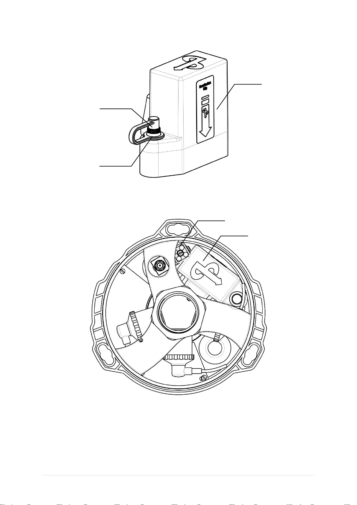
The AP Diving Rechargeable Dual Battery Pack (RB140) has been specially developed for
Vision equipped AP Diving rebreathers. The battery pack which incorporates two separate,
large capacity, power supplies –B1 & B2, is intended as an upgrade for existing customers
as well as a standard item with new AP Diving rebreathers.
•The rechargeable RB140 battery pack is compatible with Vision electronics with
V06.00.00 + firmware:
oThe V6+ firmware has a factory setting for the type of battery, non-rechargeable or
rechargeable, and once set the firmware applies the appropriate warning and switch
over levels as the batteries are depleted.
oBatteries are checked for operation during start up
oGraphical display of battery levels on rebreather handset (and HUS if fitted)
oLow battery warnings communicated on the rebreather handset, HUD, buzzer (and
HUS if fitted)
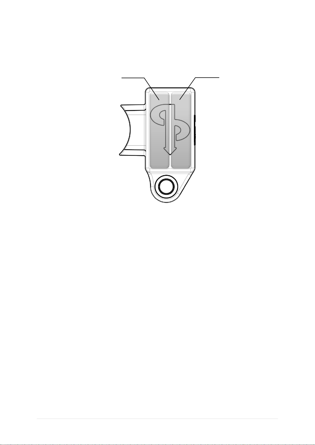
oIntelligent dual battery system using AP’s well-established technique of using B1 first,
keeping B2 in reserve until B1’s voltage diminishes enough to force the switch over to
B2 and later switch over to both batteries when the B2 voltage drops.
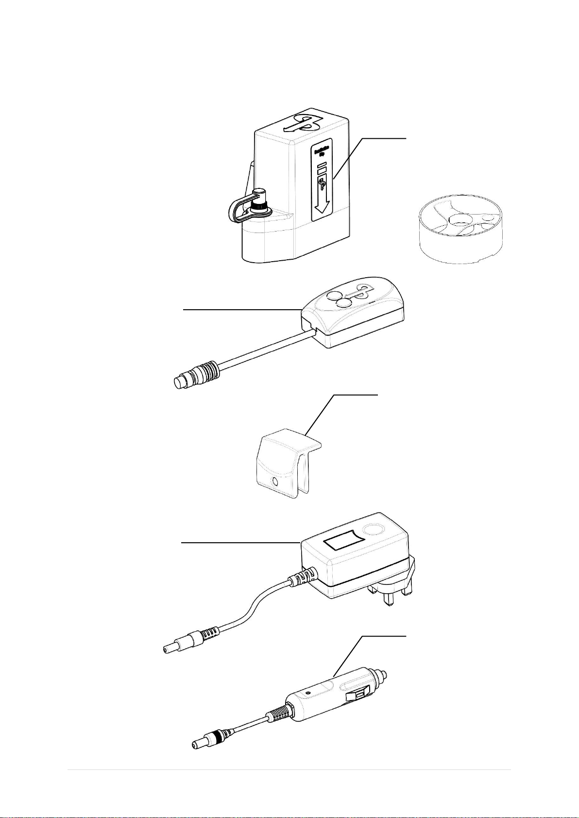
•Rechargeable from mains supply (100-240V) or 12 volt supply:
oSupplied with interchangeable mains power adaptors (types A,C,G & I) for US, EU,
UK and Australian sockets –ensuring compatibility for all mains power outlets
Worldwide.
oFor specific Country compatibility refer to:
http://www.worldstandards.eu/electricity/plug-voltage-by-country/
o12v adaptor also supplied to allow charging from 12v sockets in cars and boats.
oIntelligent battery charger applies appropriate charge to both batteries, taking approx.
4hours from completely empty to maximum charge, resorting to a trickle charge when
completed.
oIntelligent protection circuitry during use and charging
oThreaded waterproof, cap for charging port
•Advantages:
o1.8 x the capacity of the CRP2 and CR123 batteries previously used in the Vision
electronics, so re-charging is required less often than new battery insertion on
previous battery boxes, typically keeping B2 in reserve & requiring a recharge every
15-27 hours of diving depending on type of solenoid fitted, work rate, temperature and
use of backlight.
oBattery lifetime of approximately 500 charging cycles (typical of lithium-ion polymer
batteries)
oMore convenient in remote locations
oHardwired to the rebreather controllers ensuring uninterrupted power supply
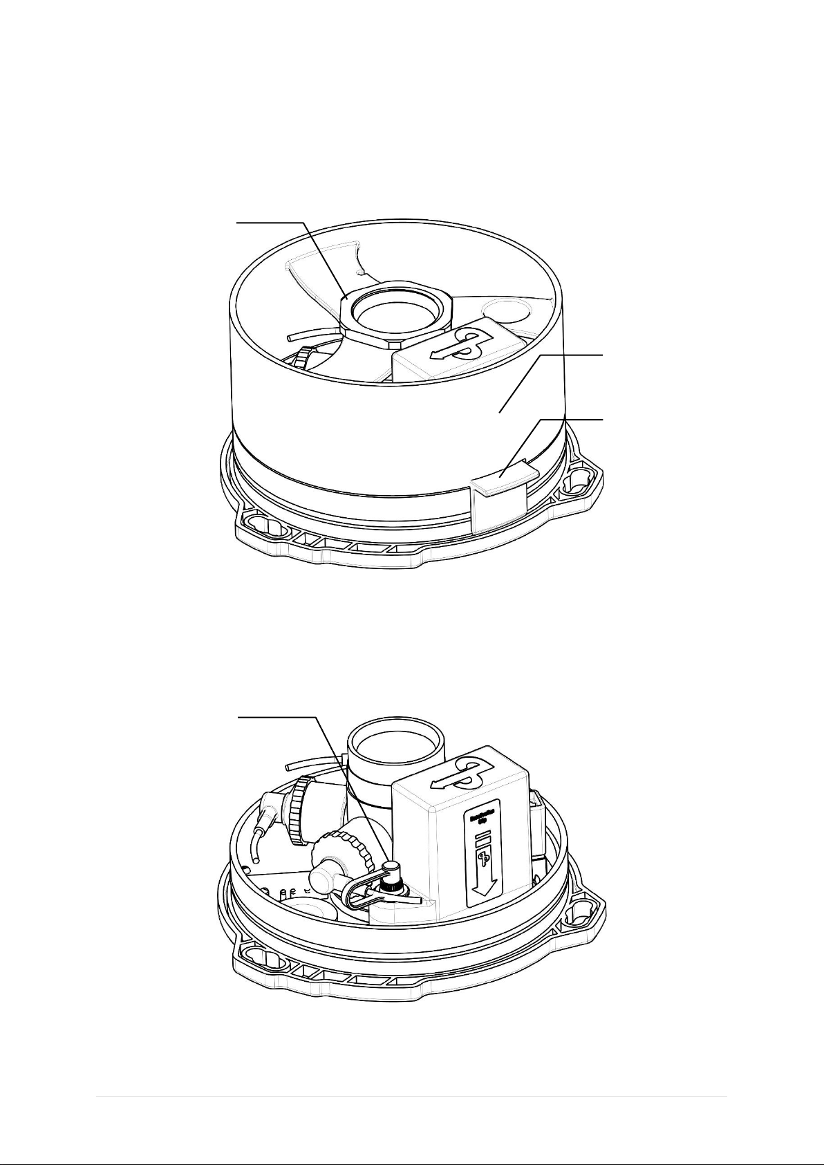
•Factory fitted and encapsulated to isolate from the breathing gas
•Located in the warmest part of the loop ensuring best possible performance in
extreme cold.
•B1 & B2 individually isolated, physically and electrically.
•Supplied with deactivation clip and new mixing chamber that allows deactivation for
travelling and transportation. The use of the deactivation clip also prevents accidental
auto activation when the handset is kept in damp conditions
•Type Tested for CE approval according to the EN14143:2013 Rebreather standard
(Notified Body: SGS United Kingdom Ltd)

4 |P a g e A P D i v i n g R e c h a r g e a b l e B a t t e r i e s
Parts Supplied
RB06/01/90
12v power
adaptor
RB06/01/70
Dual Battery
Charger
RB06/01/60 Battery
Pack (Factory fitted
to the Rebreather
Lid complete with
new mixing
chamber cover)
RB06/01/80
Mains power
adaptor with
interchangeable
heads for UK,
EU, US and
Australia
RB06/01/72
Deactivation Clip

P a g e | 5
Rechargeable Dual Battery Configuration
Note: The Rechargeable batteries are hardwired into the rebreather controller and as such are not
user removable, but can be deactivated using the deactivation clip.
Rechargeable Batteries
Solenoid
Battery Pack
Charging
Connector Cap
Charging
Connector

6 |P a g e A P D i v i n g R e c h a r g e a b l e B a t t e r i e s
Important Information
Each oxygen controller has its own battery and circuitry. It is imperative to ensure
that both, B1 & B2, are charged sufficiently prior to diving.
The 7.4V lithium-ion polymer batteries MUST only be charged with the AP Diving
dual battery charger from mains power or 12v sockets.
The AP rechargeable battery pack must only be used with Firmware version
06.00.00 onwards as it is allows factory configuration to ensure the appropriate
warning and switch over levels are applied. If previous versions of firmware are
used with the rechargeable batteries, the rebreather WILL shut down during use,
without warning, resulting in no oxygen addition and no audible warning.
V06+ will also ensure that only B1 is used during calibration and for powering the solenoid &
handset. Should B1 drop below the pre-determined voltage the power drain will automatically
be changed to B2. Should B2 also reach the pre-determined voltage then power will be
drawn automatically from both batteries. Should the ppO2fall below 0.4 bar the power is
drawn from both batteries.
The battery life varies due to the frequency of use of the backlight and the brightness setting.
To ensure that the reserve power is as good at it can be and you get the best use from the
batteries always recharge when the low battery level on B1 is reached.
The electronics do not automatically power down when not in use, therefore it is
very important to ensure that it is switched off after use to preserve battery life.
DO: Read the rebreather instruction manual fully before using the rebreather
DO: Carry out all pre-dive checks prior to each dive
DO: Replace the charging connection cap after charging and prior to diving again
DO: Post-dive maintenance, particularly recharging the batteries after a low battery
warning
DO: Keep a record of battery usage
DO: Use the de-activation clip for shipping or flying.
DO: Switch off the rebreather when not in use, to preserve battery life, as the electronics
do not automatically power down after use
DO NOT: Ignore a low battery warning
DO NOT: Dive without recharging batteries after a low battery warning
DO NOT: Dive without the charging connection cap on
DO NOT: Recharge the batteries in a wet environment
DO NOT: Attempt to open the rechargeable battery pack as it is built as a sealed unit
and contains no user-serviceable components.

P a g e | 7
Intelligent Dual Battery System
There are two batteries within the rechargeable battery pack, B1 and B2. B1 is the battery for
oxygen controller C1; B2 is the battery for C2. Additionally, both controllers when active have
the ability to use the other controller’s battery when necessary.
If B1 is discharged, there will be no C1 controller, the same applies for B2 & C2 –no battery,
no controller. If there is sufficient charge in B1 for all operations it will automatically be used
as the Master battery. If B1 only has sufficient power to start the C1 processor, C1 will still be
the Master oxygen controller but B2 will be promoted to the Master battery status and will be
used for powering the solenoid, wrist display and HUS if fitted.
During use, the same thing happens, B2 will be promoted to Master should B1 reach the low
battery warning level. Once B2 also reaches the low battery warning the power will be drawn
from both B1 and B2. Each change will be notified to the diver via the HUD and wrist display
and HUS, if fitted, as well as the buzzer.
In the event that one of the batteries is below the low battery warning level, the power will
always be drawn from the battery with sufficient voltage.
Battery 2
Battery 1

8 |P a g e A P D i v i n g R e c h a r g e a b l e B a t t e r i e s
Rechargeable Battery Charging
The battery pack will be supplied with some charge, but we recommend that the battery is
charged before it’s first use and recharged when required using the following procedure:
1. Remove the mixing chamber cover securing nut, the mixing chamber cover itself and
the deactivation clip (if fitted) from the rebreather lid.
2. Unscrew the charging connector cap from the side of the battery pack. The rubber
lanyard should keep the cap with the lid.
Deactivation Clip
Mixing Chamber
Cover
Mixing Chamber
Cover Securing Nut
Charging
Connector Cap

P a g e | 9
3. Select either the mains power adaptor or 12v power adaptor and plug into the Dual
Charger. The mains power adaptor is supplied with 4 different heads for use with
different international power outlets. The appropriate one is simply clipped onto the
power adaptor body.
4. Before using the charger make sure that the connector is free from moisture, dirt or
corrosion as this can affect the charging process.
5. Screw the dual charger connector onto the battery pack (finger tight). Put the power
adaptor into the socket and turn on the socket to apply power to the charger.
Mains power
adaptor with
interchangeable
heads for UK,
EU, US and
Australia
Dual Charger

10 |P a g e A P D i v i n g R e c h a r g e a b l e B a t t e r i e s
6. The dual charger will light up showing the charge status of each battery within the
battery pack.
Green = Fully Charged
Red = Charging
Flashing Red = Charging Error –Contact AP Diving
No Lights = Power is not applied to the charger or the charger is not
Connected to the lid correctly
The image here shows B1 charging and B2 fully charged. When both B1 and B2 show green
the batteries are fully charged and ready for use.
It is not recommended to leave the battery on charge for long periods after the battery pack
has reached full charge (green light shown on both B1 and B2).
7. Turn the power off, remove the charger and adaptor and replace the charging
connector cap. This cap protects the connector and batteries from moisture damage
when in use. The mixing chamber cover and securing nut can now be replaced and
the lid can be assembled onto the scrubber.
Charging
Connector Cap
B1
B2

P a g e | 11
Initial Switch-On Tests
As with all AP rebreathers produced, an electronic check of connected devices is done on
first switch-on and this includes an initial battery check.
Scenario 1: Initial switch-on finds two batteries with readable voltage levels
Handset proceeds to display connection status for Oxygen cells, solenoid, buzzer,
temperature stick and CO2monitor (if fitted), followed by “loaded” battery test.
Scenario 2: Initial switch-on finds two dead batteries
If both batteries are too low the unit will not switch on and in this extremely low
battery state the Self-activation features (if fitted) will not function;
Scenario 3: Initial switch-on finds one dead or low battery and one good one.
If only one battery has sufficient voltage to power it’s oxygen controller the following screen is
displayed, indicating which controller is missing, in this case –C1 and the option to Dive
Now? Yes or No is given.
WARNING –Selecting to continue the dive with only one healthy battery is a
feature that should only be used in an emergency, such as returning from a cave
dive with no other means of escape. Depleted batteries should always be recharged,
if at all possible.
FAILED SELF TEST
C1 NO CONTROLLER
DIVE NOW ?
YES
NO

12 |P a g e A P D i v i n g R e c h a r g e a b l e B a t t e r i e s
If Yes is selected then the unit will display the connection results for oxygen cells, solenoid,
buzzer, temperature stick and CO2sensor (if fitted) and then move onto the normal battery
test:
In this scenario, B1 has insufficient voltage and, as there is no B1- there is no C1 (Controller
1). C1 cannot measure anything, as it’s not switched on, so 0.0v is displayed for both B1 and
B2 in the C1 column. C2 is working properly and reports 6.3v for it’s own battery (B2) and
0.0v for B1.
Scenario 4: Initial switch-on finds two low batteries.
If both the battery readings are low a “Failed Self-Test” screen will appear, followed by “NO
DIVE”.
C1 BATTERY TEST C2
0.0V B1 0.0V
0.0V B2 6.3V
C1 BATTERY C2
NO DIVE

P a g e | 13
Normal Pre-Dive Operation
Once the initial connectivity tests are completed, to help reduce the possibility of starting a
dive with weak batteries, the solenoid “load” is placed on each battery in turn, while the
battery voltages are measured by both oxygen controllers, C1 and C2.
Note: Although the fully charged Lithium Polymer batteries are nominally 7.4 volts each, in
order to make the rechargeable battery pack compatible with the A/D convertor range of
legacy systems, the display during the battery tests will not show voltages higher than 6.3
volts, so 3 squares indicates 6.3volts +.
Nominal battery voltage levels:
= 3 squares = Good level (6.3 volts +)
= 2 squares = 6.25 volts, recharge before a decompression dive
= 1 square = 6.0 volts. If occurring pre-dive on both batteries you
will see “LOW BATTERY, NO DIVE”. If the other battery has 2
squares or more you will see the prompt “LOW BATTERY
DIVE NOW, Y OR N?”
= 0 squares = 5.8 volt. If occurring during the dive you will see
and hear the low battery warning and it will switch to B2.
Scenario 1:
Two good batteries
Handset proceeds to “Open Oxygen Valve”
C1 BATTERY TEST C2
6.3V B1 6.3V
6.3V B2 6.3V

14 |P a g e A P D i v i n g R e c h a r g e a b l e B a t t e r i e s
Scenario 2:
One part used battery, one good battery
Handset proceeds to “Open Oxygen Valve”
Scenario 3:
One low battery, one good battery
If one battery reading is low, one or zero squares, and the other battery has two or more
squares the “SELF-TEST, BATTERY, DIVE NOW YES OR NO?” screen will appear.
C1 BATTERY TEST C2
6.1V B1 6.1V
6.3V B2 6.3V
C1 BATTERY TEST C2
6.1V B1 6.1V
6.3V B2 6.3V

P a g e | 15
Careful consideration is required at this time:
-Is the planned dive a long duration or decompression dive?
-Does the reserve battery C2 have three squares or two?
-Will I be diving in cold water?
It is your personal decision as to whether you can proceed or delay the dive until you
have recharged the batteries but clearly if the answer to either of the above questions
is yes, then it would be foolhardy to proceed without charging.
During the battery test there is no “battery parachute”, the system which allows the 2nd
battery to take over from the first in the event of a “voltage collapse”.
If both battery compartment voltages are so low that the voltage drops below the
“brown out” value then the system will simply shut down and the battery pack will need
to be recharged prior to use.
In this extremely low battery state the Self-activation features (if fitted) will not function.
Selecting to continue the dive with only one healthy battery is a feature that should
only be used in an emergency, such as returning from a cave dive with no other
means of escape. Spent or missing batteries should always be recharged if at all
possible.
C1 SELF TEST C2
BATTERY
DIVE NOW?
YES NO

16 |P a g e A P D i v i n g R e c h a r g e a b l e B a t t e r i e s
Dive Mode Operation
Master / Slave Batteries
The battery management is very simple, largely done for you automatically, keeping B2 in
reserve as much as possible.
If C1’s battery, B1, has sufficient power to qualify as the Master battery, then the electronics
will always start up with B1 as the Master battery. The Master battery is used to power the
wrist mounted display, the solenoid and the HUS (if fitted).
The Master battery is highlighted, shown here on the left:
If B1 has insufficient voltage to be the Master battery then C2’s battery (B2) will be
designated as the Master battery. In use, it will be possible to see C1 as the Master controller
but B2 being used as the Master battery. In the same way it would be possible to see C2 as
the Master controller but using B1 as the Master battery.
In the event that both B1 and B2 are below the low battery levels then the power to drive the
wrist display and the solenoid is drawn from both batteries simultaneously.
Nominal battery voltage levels:
= 3 squares = Good level (6.3 volts +)
= 2 squares = 6.25 volts, recharge before a decompression dive
= 1 square = 6.0 volts. If occurring pre-dive on both batteries you
will see “LOW BATTERY, NO DIVE”. If the other battery has 2
squares or more you will see the prompt “LOW BATTERY
DIVE NOW, Y OR N?”
= 0 squares = <5.8 volt. If occurring during the dive you will see
and hear the low battery warning and it will switch to B2

P a g e | 17
Low Battery Warning
BEEP
A low battery warning is indicated by alternating red/green/red/green etc flashing lights in C1
or C2 or both if both batteries are low.
In the example above C1’s HUD is indicating a low battery and this is confirmed in the
display, by showing red then green, red then green etc. When the B1 battery hits its LOW
Battery threshold B2 is automatically promoted to Master status and B2 is then used to
supply power to the wrist mounted display and solenoid. B2 can be seen above to be
highlighted indicating it is already at Master status.
C1 1.30
1.31 1.29 1.30
B1
LOW BATTERY
C1 C2

18 |P a g e A P D i v i n g R e c h a r g e a b l e B a t t e r i e s
Battery Warning Suppression
If you decide to stay on the rebreather the LOW BATTERY warning
-may be temporarily suppressed by pressing and holding the right switch for 2
secs plus. The HUD, HUS (if fitted) and buzzer warnings will then be suppressed,
leaving the wrist display showing the Battery Warning.
-promoting C2 to master, by switching off C1 then turning it back on again ensures
there is little load now placed on B1 and low voltage alarms will be less frequent.
Do not ignore low battery warnings. If the battery power to the unit depletes
completely, the whole rebreather life support will stop functioning and there will no
longer be any warnings. This can lead to serious injury or death.
For protection, each battery has a low voltage protection circuit incorporated, so
when the voltage drops to these critically low levels, the power will stop abruptly.
Atmospheric temperature can have an effect on the battery life. In lower
temperatures the battery life will decrease.
Post Dive
Actions to take after a LOW BATTERY warning is displayed
The best battery management technique is to simply recharge straight after a dive that had a
B1 Low Battery Warning. This way, you always have a well charged battery in B2 effectively
in reserve.

P a g e | 19
Dive Log / Log Viewer
When viewing your dive downloads in the AP LogViewer, any low battery warnings given
during the dive are shown in the bottom left.
When moving the cursor across the dive, low battery warnings are shown in red when
alarming and black when supressed.

20 |P a g e A P D i v i n g R e c h a r g e a b l e B a t t e r i e s
Alternatively, the battery voltages may be seen throughout the dive by selecting Chart
Options and selecting the battery voltages option. As you move the cursor across the dive
the battery voltages as measured by each controller can be seen bottom right.
Battery Voltages
Table of contents