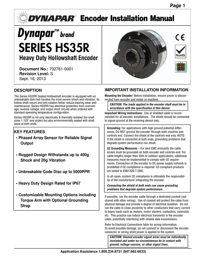
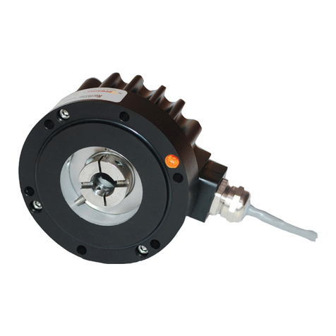
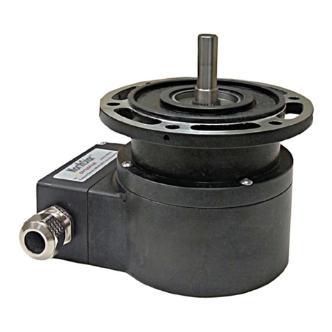
DYNAPAR HS20 Series Service manual

Dynapar brand Encoder
Technical Bulletin
Bulletin Number: 702375-0001
Revision Level: J
Date: July 27, 2014
1675 Delany Road
Gurnee, IL 60031-1282
Phone: 847.662.2666
Fax: 847.662.4150
Application Assistance 1.800.234.8731
DESCRIPTION
SPECIFICATIONS
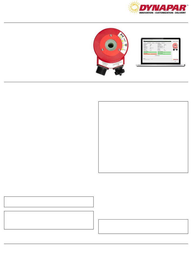
Series HS20 Sealed Hollow Shaft
The Dynapar brand Series HS20 Sealed
Hollowshaft encoder is designed for easy
installation on motor or machine shafts. Its
hollowshaft design eliminates the need for a
flexible shaft coupling, mounting bracket,
flower pot, or flange adapter. This not only
reduces the installation depth, but also lowers
total cost.
The Series HS20 Sealed Hollowshaft's floating
shaft mount and spring tether minimize
bearing loads and eliminate flexible shaft
couplings to reduce wear and maintenance.
STANDARD OPERATING CHARACTERISTICS
Code: Incremental
Resolution: 50 to 2540 PPR (pulses/
revolution)
Accuracy: (worst case any edge to any
other edge) <1024 PPR (metal disk): ±7.5
arc-min.
≥1024 PPR (glass disk): ±2.5 arc-min.
Format: Two channel quadrature (AB) with
optional Index (Z) and complementary
outputs
Phase Sense: A leads B for CCW shaft
rotation viewing the hub clamp end of the
encoder
Quadrature Phasing: 90°±22.5°
electrical
Symmetry: 180°±18°electrical
Index: 180°+18°/-135°electrical (gated
with B low)
Waveforms: Squarewave with rise and fall
times less than 1 microsecond into a load
capacitance of 1000 pf
ELECTRICAL
Input Power:
5 to 26 VDC at 100 mA max., not including
output loads
Outputs:
7273 Open Collector: 30 VDC max., 40 mA
sink max.
7272 Push-Pull and Differential Line
Driver: 40 mA sink or source
Frequency Response: 100 kHz min. (index
75 kHz min. for extended temperature range)
Electrical Protection: Overvoltage, reverse
voltage and output short circuit protected
Noise Immunity: Tested to EN61326-1 EMC
(Heavy Industrial) for Electro Static Discharge,
Radio Frequency Interference, Electrical Fast
Transients, Conducted and Magnetic Interfer-
ence
Mating Connector:
6 pin, style MS3106A-14S-6S (MCN-N4);
7 pin, style MS3106A-16S-1S (MCN-N5);
10 pin, style MS3106A-18-1S (MCN-N6);
5 pin, style M12: Cable with connector available
8 pin, style M12: Cable with connector available
MECHANICAL
Bearing Life: (at maximum tether loading)
Standard tether: 5x10⁹ revolutions
Slotted tether: 8x10⁹ revolutions
Shaft Speed: 6000 RPM max.
Shaft Bore Tolerance: Nominal +0.0002"/
+0.0008" (+0.005/+0.020 mm)
Mating Shaft Requirements:
Runout: ±0.005" (±0.13mm) radial, max.
Endplay: ±0.050" (±1.27 mm) axial, max.
Length: 0.80" (20 mm), minimum
Starting Torque: 3.0 oz-in max.
Moment of Inertia: 5.1 x 10⁻⁴ oz–in–sec2
Weight: 10 oz. max.
ENVIRONMENTAL
Operating Temperature:
Standard: 0 to +70°C
Extended: 0 to +85 °C (consult factory for low
temperature operation to –40 °C)
Storage Temperature: –40 to +85°C
Shock: 50 G’s for 11 milliseconds duration
Vibration: 5 to 2000 Hz at 2.5 G’s
Humidity: to 98% without condensation
Enclosure Rating: NEMA4/IP65 (dust proof,
washdown)
IMPORTANT ENCODER INSTALLATION INFORMATION
Mounting the Encoder: The encoder should be mounted such that its shaft
is in close as possible alignment with the axis of the driving machine or
motor shaft.
CAUTION: The loads applied to the encoder shaft must be in
accordance with the specificatios of this device.
Important Wiring Instructions: Use of shielded cable is recommended for
all encoder installations. The shield should be connected to signal-ground
at the receiving device only.
Grounding: For applications with high ground potential differences,
DO NOT ground the encoder through both machine and controls end.
Connect the shield at the controls end only. NOTE: If the shield is
connected at both ends, grounding problems that degrade system
performance can result.
CE Grounding Measures – For best EMC immunity the cable screen
must be grounded on both encoder and controls end. For cable
lengths longer than 30m or outdoor applications, additional measures
must be implemented to comply with CE requirements. Connection of
the encoder to DC power supply network is prohibited if CE compli-
ance is required. CE-compliant products are tested to EN61326-1
EMC.
In all cases, system CE compliance is ultimately the responsibility of
the manufacturer integrating the encoder.
Connecting the shield at both ends can cause grounding problems
that degrade system performance.
If possible, run the encoder cable through a dedicated conduit (not shared
with other wiring). Use of conduit will protect the cable from physical
damage and provide a degree of electrical isolation. Do not run the cable
in close proximity to other conductors that carry current to heavy loads
such as motors, motor starters, contactors, solenoids, etc. This practice
can induce electrical transients in the encoder cable, potentially interfering
with reliable data transmission.
Refer to Electrical Connections table for wiring information. To avoid
possible damage, do not connect or disconnect the encoder connector or
wiring while power is applied to the system.
CAUTION: Unused encoder signal wires must be individually
insulated and under no circumstances be in contact with ground,
voltage sources, or other signal lines.

Models Information
Dimensions
MS CONN MS CONN
1.97"
[50.0]
H, J
M12 CONN
0.300" TYP
6.60"
0.48 THRU
HOLES ON
5.875 B.C.
(6 PLACES)
3.300"
Ordering Information
Code 2: PPR
Code 8: Options
available when
Code 7 is 0 - 7
PS LED
Output
Indicator
Code 1: Model
HS20 Size 20
heavy-duty,
sealed
hollowshaft
encoder
0300
0360
0400
0720
0800
1000
1024
Code3:Bore Size
06 mm
11/4"
25/16"
38 mm
43/8"
510 mm
612 mm
71/2"
85/8"
915 mm
A16 mm
0None - customer
supplied
1Clearance hole for
3/8" bolt on 5.88"
dia. bolt circle
(to fit 4-1/2" NEMA
C-face)
3Slotted hole for
bolt on 1.87" to 2.95"
radius
4Same as '1', w/
protective cover kit
5Same as '3', w/
Protective cover kit
Code 5: Format
0single ended,
undirectional (A)
1single ended,
bidirectional (AB)
2single ended,
bidirectional with
index (ABZ)
available when Code 6
is 3, 4, A or B:
3differential,
bidirectional ( AA
BB)
available when Code 6
is 3, 4, A or B and
code 7 is 2, or
7 thru G:
4differential,
bidirectional with
index ( AA BB ZZ)
Code6:Output
05-26V in, 5-26V
open collector out
15-26V in, 5-26V
open collector out
w/ 2.2kΩpullups
25-26V in, 5-26V
push-pull out
available when Code 5 is
3 or 4:
35-26V in, 5V line
driver out
45-26V in, 5-26V
line driver out
Asame as '3' with
extended temp.
Bsame as '4' with
extended temp.
Code 7:Termination
06 pin connector
17 pin connector
210 pin connector
56 pin connector,
plus mating
connector
67 pin connector,
plus mating
connector
710 pin connector,
plus mating
connector
A18" cable
B36" cable
C72" cable
D10' cable
F13" cable
with 10 pin
connector plus
mating connector
G13" cable
J8 Pin M12
Connector
available when Code 5
is 0 thru 2
H5 Pin M12
Connector
HS20
0050
0060
0100
0200
0250
0256
Code 4: Fixing
1200
1250
1270
1500
1600
1800
Metal Disk:
Glass Disk:
1968
2000
2048
2400
2500
2540
112096-0001 Tether Kit (clearance hole for 3/8" bolt on 5.88" diameter bolt-circle)
112096-0002 Tether Kit (slotted hole for bolt on 1.87" to 2.75" radius)
112105-0001 Protective Cover Accessory
B14 mm
0180

Wiring Information
Sig. A
Sig. B
Sig. Z
Power +V
N/C
Com
Case
Sig. A
Sig. B
Sig. Z
Encoder
Function
E
D
C
B
F
A
—
—
—
—
Pin
BRN
ORN
YEL
RED
—
BLK
—
—
—
—
Cable
#108594-*
6 Pin
Single Ended
Wire
Color Pin
BRN
ORN
—
RED
—
BLK
GRN
BRN/WHT
ORN/WHT
—
A
B
—
D
—
F
G
C
E
—
Cable
#108596-*
7 Pin Dif Line
Drv w/o Idx
Wire
Color Pin
BRN
ORN
YEL
RED
—
BLK
GRN
—
—
—
A
B
C
D
E
F
G
—
—
—
Cable
#108595-*
7 Pin
(If Used)
Wire
Color
A
B
C
D
E
F
G
H
I
J
Pin
Cable
#1400635-*
10 Pin
(If Used)
Wire
Color
_
_
_
BRN
ORN
YEL
RED
—
BLK
GRN
BRN/WHT
ORN/WHT
YEL/WHT
Cable
#112123-*
6 Pin Dif Line
Drv w/o Idx
Pin
Wire
Color
E
D
—
B
—
A
—
C
F
—
BRN
ORN
—
RED
—
BLK
—
BRN/WHT
ORN/WHT
—
Connector pin numbers and cable assembly wire color information
is provided here for reference.
5 & 8 Pin M12 Accessory Cables when Code 7= H or J
Encoder Cable # 112859- Cable # 112860- Cable # 112860-
Function 5 Pin Single Ended 8 Pin Single Ended 8 Pin Differential
Pin Wire Color Pin Wire Color Pin Wire Color
Sig. A
Sig. B
*Sig. Z
Power +V
Com
4
2
5
1
3
–
–
–
Sig. –
A
Sig. –
B
*Sig. –
Z
BLK
WHT
GRY
BRN
BLU
–
–
–
1
4
6
2
7
–
–
–
BRN
ORG
YEL
RED
BLK
–
–
–
1
4
6
2
7
3
5
8
* Index not provided on all models. See ordering information
Cable Configuration: PVC jacket, 105 °C rated, overall foil
shield; 24 AWG conductors, minimum
Cable Configuration: PVC jacket, 105 °C rated, overall foil
shield; 3 twisted pairs 26 AWG (output signals), plus 2 twisted
pairs 24 AWG (input power)
Connector & mate/accessory cable assembly pin numbers and wire color information is provided here for
reference. HS20 models with direct cable exit carry the same color coding as shown for each output configurati
o
6, 7 & 10 Pin MS Connectors and Cables - Code 7= 0 to 7, A to G
BRN
ORG
YEL
RED
BLK
BRN/WHT
ORG/WHT
YEL/WHT
www.dynapar.com
European Sales Representitive
Hengstler GmbH
Uhlandstrasse 49, 78554 Aldingen
Germany
www.hengstler.com
Customer Service:
Tel.: +1.800.873.8731
Fax: +1.847.662.4150
custserv@dynapar.com
Technical Support
Tel.: +1.800.234.8731
Fax: +1.847.662.4150
northstar.techsupport@dynapar.com
Table of contents
Other DYNAPAR Media Converter manuals

DYNAPAR
DYNAPAR SERIES HS35R User manual

DYNAPAR
DYNAPAR NorthStar HD35R Series User manual

DYNAPAR
DYNAPAR NorthStar NexGen RIM Tach HT85 User manual

DYNAPAR
DYNAPAR HS35IQ Series User manual

DYNAPAR
DYNAPAR NorthStar HSD44 Series User manual

DYNAPAR
DYNAPAR SLIM Tach SL85 User manual

DYNAPAR
DYNAPAR M21 Series User manual

DYNAPAR
DYNAPAR NorthStar Rim Tach RT8500 User manual

DYNAPAR
DYNAPAR NorthStar SLIM Tach ST56 User manual

DYNAPAR
DYNAPAR NorthStar SLIM Tach SL56 User manual