manuals.online logo
Brands
  1. Home
  2. •
  3. Brands
  4. •
  5. Apollo
  6. •
  7. Security System
  8. •
  9. Apollo 55000-278 User manual

Apollo 55000-278 User manual

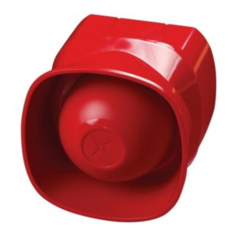
Multi-tone Open-area Alarm Devices
Installation Guide
General
This guide describes the installation of the following products:
Part Number Product Name Type Colour
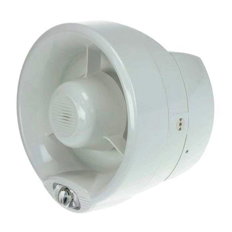
55000-278 Multi-tone Open-area Sounder Indoor (Type A) Red
55000-279 Multi-tone Open-area Sounder Indoor (Type A) White
55000-274 Multi-tone Weatherproof Open-area Sounder Outdoor (Type B) Red
55000-275 Multi-tone Weatherproof Open-area Sounder Outdoor (Type B) White
55000-293 Multi-tone Open-area Sounder Beacon with Isolator Indoor (Type A) Red
55000-294 Multi-tone Open-area Sounder Beacon with Isolator Indoor (Type A) White
55000-291 Multi-tone Open-area Sounder Beacon Indoor (Type A) Red
55000-292 Multi-tone Open-area Sounder Beacon Indoor (Type A) White
55000-298 Multi-tone Weatherproof Open-area Sounder Beacon
with Isolator
Outdoor (Type B) Red
55000-299 Multi-tone Weatherproof Open-area Sounder Beacon
with Isolator
Outdoor (Type B) White
55000-296 Multi-tone Weatherproof Open-area Sounder Beacon Outdoor (Type B) Red
55000-297 Multi-tone Weatherproof Open-area Sounder Beacon Outdoor (Type B) White
The Multi-tone Open-area Alarm Devices are connected to control panels which use the
Discovery or XP95 protocol. It complies with the requirements of EN54–3: 2001. Versions with
isolator also comply with EN54–17: 2005.
Tones incorporated in the product are:
Apollo Standard Tone, Slow Whoop Tone to NEN2575 and DIN 33404 Tone. There are 2 volume
settings in each variant.
The versions which incorporate a short-circuit isolator have a yellow indicator LED, which illumi-
nates through the lens if a short circuit is detected on the loop wiring.
Mounting the backbox
The backbox is removed by using either an unlocking key (Type A versions) to press in one of
the retaining lugs, or a hex driver (Type B versions).
The Type A product has 6 slotted knockouts on the backbox and is installed directly to the
mounting surface. For the Type B product, fit the backbox to the mounting surface with four
screws using the holes in each corner (see Fig 1). Do not drill through the backbox.
To ensure that there is a good seal between the back box and the unit, the mounting surface
should be as flat as possible and the mounting screws not over tightened.
Wiring Details
Note: This product is polarity sensitive (supply reversal protected) and will not function if wired
incorrectly.
Drill holes for cable entry as appropriate for the installation. Drill guides are marked on the
backbox. To maintain the integrity of the Type B product it is essential that suitable cable
glands be used.
Connect the loop cables to the terminal block, observing polarity and functional earth/screen
if applicable. The wiring terminals accept solid or stranded cables up to 2.5mm².
The maximum number of Multi-tone Open-area Alarm Devices permitted between standard
XP95 isolators (part no. 55000-720) or isolating bases (part no. 45681-321/284) is 20, depending
on the loop loading. Apollo's Loop Calculator is a program available as a free download from
www.apollo-fire.co.uk and can be used to check the loading of any proposed loop design.
PP2248/Issue 9
©Acorn Fire & Security LTD
Group Address Setting
In group mode the Multi-tone Open-area Alarm Devices responds to an additional address
referred to as the group address, which is used to activate groups of sounders simultaneously.
Individual units continue to respond to their own addresses and report their status in the normal
way. A group address is set on a four-segment DIL switch which is factory set to 0000. A group
address may be any spare address within–and only within–the range 112 to 126 inclusive. The
required group address is set in accordance with the following table.
DIL switch DIL switch DIL switch
setting setting setting
addr 1234 addr 1234 addr 1234
112 1111 117 0101 122 1010
113 0111 118 1001 123 0010
114 1011 119 0001 124 1100
115 0011 120 1110 125 0100
116 1101 121 0110 126 1000
Note: group mode is disabled if the group address DIL switch is set to 0000, irrespective of the
protocol message.
Commissioning
It is important that the Multi-tone Open-area Alarm Devices be fully tested after installation. An
XP95 Test Set, part no. 55000-870, may be used to carry out functional testing of individual units.
The test set can also perform data integrity tests of an entire system.
Troubleshooting
Before investigating individual units for faults, it is important to check the system wiring is fault-
free. Earth faults on data loops may cause communication errors.
Fault Finding
Problem Possible Cause
No response or missing Incorrect address setting
Incorrect loop wiring (polarity reversed)
Too many sounder beacons between isolators
Analogue value 2 Beacon failed (Sounder Beacon version only)
Analogue value 4 Incorrect group or individual address setting
Device fault Incorrect group address setting
Device fails to operate Control panel has incorrect cause and effect programming
Incorrect group address setting
Locking Mechanism
To meet the requirements of EN54 Part 3 and the Construction Products Directive, the devices
have been designed to lock to its base. To release the Type A device from its base, a release
key (supplied) must be used to release the latch in the side of the base. To unlock the Type B
(Weatherproof) versions, a hex driver (supplied) is required.
www.acornfiresecurity.com
Technical Data
Operating voltage 18–28V DC
Maximum Loop Current Consumption at 24V
Switch-on surge 1.2mA for <1 sec
Quiescent 330μA
Sounder operated 5mA
Sounder Beacon Operated: 92/100dB(A) 8/9mA
Sound output 100dB(A)
IP rating - Type A 21C
IP rating - Type B 66C
For sound pressure levels measured to EN54–3 see document PP2203 and for isolator operation
information see document PP2090, both available on request.
IP rating
To maintain the integrity of the enclosure it is essential that suitable IP rated cable glands be
used.
Individual Address Setting
The address of the Multi-tone Open-area Alarm Devices is set using seven segments of the
eight-segment DIL switch. The eighth segment is used to adjust the volume output. Segments
1-7 of the switch are set to “0” (ON) or “1”, using a small screwdriver or similar tool. A complete
list of address settings is shown below.
DIL switch DIL switch DIL switch DIL switch DIL switch
setting setting setting setting setting
addr 1234567 addr 1234567 addr 1234567 addr 1234567 addr 1234567
1 1000000 11 1101000 21 1010100 31 1111100 41 1001010
2 0100000 12 0011000 22 0110100 32 0000010 42 0101010
3 1100000 13 1011000 23 1110100 33 1000010 43 1101010
4 0010000 14 0111000 24 0001100 34 0100010 44 0011010
5 1010000 15 1111000 25 1001100 35 1100010 45 1011010
6 0110000 16 0000100 26 0101100 36 0010010 46 0111010
7 1110000 17 1000100 27 1101100 37 1010010 47 1111010
8 0001000 18 0100100 28 0011100 38 0110010 48 0000110
9 1001000 19 1100100 29 1011100 39 1110010 49 1000110
10 0101000 20 0010100 30 0111100 40 0001010 50 0100110
51 1100110 61 1011110 71 1110001 81 1000101 91 1101101
52 0010110 62 0111110 72 0001001 82 0100101 92 0011101
53 1010110 63 1111110 73 1001001 83 1100101 93 1011101
54 0110110 64 0000001 74 0101001 84 0010101 94 0111101
55 1110110 65 1000001 75 1101001 85 1010101 95 1111101
56 0001110 66 0100001 76 0011001 86 0110101 96 0000011
57 1001110 67 1100001 77 1011001 87 1110101 97 1000011
58 0101110 68 0010001 78 0111001 88 0001101 98 0100011
59 1101110 69 1010001 79 1111001 89 1001101 99 1100011
60 0011110 70 0110001 80 0000101 90 0101101 100 0010011
101 1010011 106 0101011 111 1111011 116 0010111 121 1001111
102 0110011 107 1101011 112 0000111 117 1010111 122 0101111
103 1110011 108 0011011 113 1000111 118 0110111 123 1101111
104 0001011 109 1011011 114 0100111 119 1110111 124 0011111
105 1001011 110 0111011 115 1100111 120 0001111 125 1011111
126 0111111
Fig 3. Example of address and tone setting
Tone Setting
56Tone
00 Standard
10 SlowWhoop
01 DIN
11 Standard
© Apollo Fire Detectors Limited 2006-9/JDR/TP
12345678
O
N123456
O
N
Individual Address Vol Group
Address
Tone
011101011101
Individual
Address 78 =
Group
Address 113 =
Tone setting
Standard =
Example: Volume
92dB =
0 0
ON = 0
Switch
MOUNTING HOLES
FOR WEATHERPROOF
INSTALLATION
USE IP RATED CABLE GLANDS
©Apollo Fire Detectors Limited 2012/EKC
ENSURE THAT THERE IS A GOOD SEAL BETWEEN
THE BACK BOX AND THE UNIT, THE MOUNTING SURFACE
SHOULD BE AS FLAT AS POSSIBLE
ALIGN MATING MARKS
L1(-)
Screen
L1(-)
Screen
L2(+)
L2(+)
L2(+)L1(-)
L1(-)
L2(+)
12345678
O
N123456
O
N
Individual Address Vol Group
Address
Tone
ON = 0
© Apollo Fire Detectors Limited 2006-9/JDR/JLC/TP/EKC
Fig 2. Wiring
Fig 1. Mounting Type B weatherproof products
www.acornfiresecurity.com
This manual suits for next models

11

Other Apollo Security System manuals

Apollo 51000-305 User manual

Apollo

Apollo 51000-305 User manual

Apollo Marine & Offshore MCP2A-R470SF-A071-02 User manual

Apollo

Apollo Marine & Offshore MCP2A-R470SF-A071-02 User manual

Apollo REACH WIRELESS RW1500-210APO User manual

Apollo

Apollo REACH WIRELESS RW1500-210APO User manual

Apollo REACH WIRELESS RW1000-400APO User manual

Apollo

Apollo REACH WIRELESS RW1000-400APO User manual

Apollo XP95 IS User manual

Apollo

Apollo XP95 IS User manual

Apollo 33 404 Operating and maintenance instructions

Apollo

Apollo 33 404 Operating and maintenance instructions

Apollo REACH WIRELESS RW1500-110APO User manual

Apollo

Apollo REACH WIRELESS RW1500-110APO User manual

Apollo 51000-357 User manual

Apollo

Apollo 51000-357 User manual

Apollo REACH WIRELESS RW1900-901APO User manual

Apollo

Apollo REACH WIRELESS RW1900-901APO User manual

Apollo Smoke Detector XP95 Operating and maintenance instructions

Apollo

Apollo Smoke Detector XP95 Operating and maintenance instructions

Apollo 55100-021 MAR User manual

Apollo

Apollo 55100-021 MAR User manual

Apollo REACH WIRELESS RW1500-210APO User manual

Apollo

Apollo REACH WIRELESS RW1500-210APO User manual

Apollo 55000-278 User manual

Apollo

Apollo 55000-278 User manual

Popular Security System manuals by other brands

shelyak Dome Tracker PF0004 user guide

shelyak

shelyak Dome Tracker PF0004 user guide

OVA AIS-SART S9000 user manual

OVA

OVA AIS-SART S9000 user manual

KingShield ACOMN instructions

KingShield

KingShield ACOMN instructions

Clover BUN 1460 datasheet

Clover

Clover BUN 1460 datasheet

Intelbras XSS 8000 user guide

Intelbras

Intelbras XSS 8000 user guide

Pneumercator LC1000 SERIES instruction manual

Pneumercator

Pneumercator LC1000 SERIES instruction manual

Wolf ProScaler user manual

Wolf

Wolf ProScaler user manual

Bosch LTC 1311/20 FlexiDome I Operator's manual

Bosch

Bosch LTC 1311/20 FlexiDome I Operator's manual

Vanderbilt IPAW8-10 instructions

Vanderbilt

Vanderbilt IPAW8-10 instructions

NAPCO StarLink Connect Series installation instructions

NAPCO

NAPCO StarLink Connect Series installation instructions

Texecom Premier 412 user guide

Texecom

Texecom Premier 412 user guide

Konig SEC-APC10 manual

Konig

Konig SEC-APC10 manual

Vacron VVH-MDE308 user manual

Vacron

Vacron VVH-MDE308 user manual

ITI WIS installation instructions

ITI

ITI WIS installation instructions

Chamberlain CWA2000 user manual

Chamberlain

Chamberlain CWA2000 user manual

ADEMCO Security System VISTA-15 Installation and setup guide

ADEMCO

ADEMCO Security System VISTA-15 Installation and setup guide

Tiiwee X4 Motion Sensor Alarm user manual

Tiiwee

Tiiwee X4 Motion Sensor Alarm user manual

Siemens FDCAI181 product manual

Siemens

Siemens FDCAI181 product manual

manuals.online logo
manuals.online logoBrands
  • About & Mission
  • Contact us
  • Privacy Policy
  • Terms and Conditions

Copyright 2025 Manuals.Online. All Rights Reserved.