Apollo Marine & Offshore MCP2A-R470SF-A071-02 User manual
Other Apollo Security System manuals
Apollo
Apollo REACH WIRELESS RW1500-210APO User manual
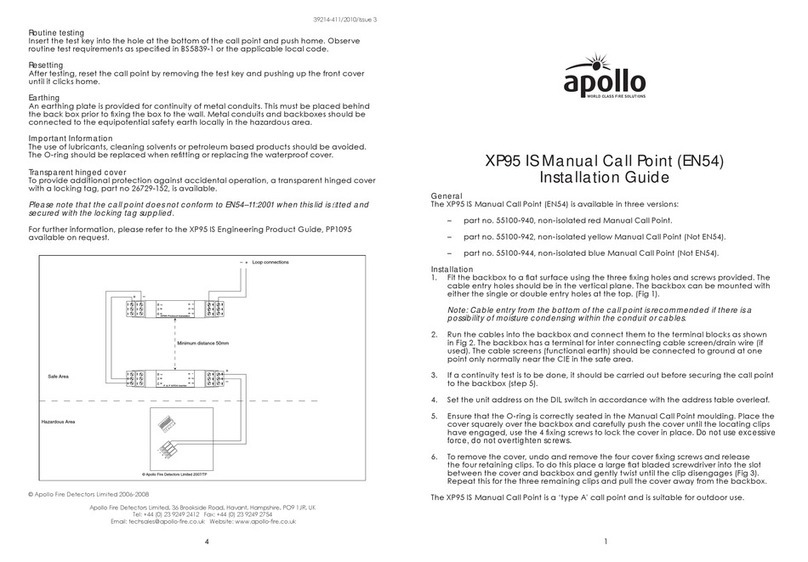
Apollo
Apollo XP95 IS User manual
Apollo
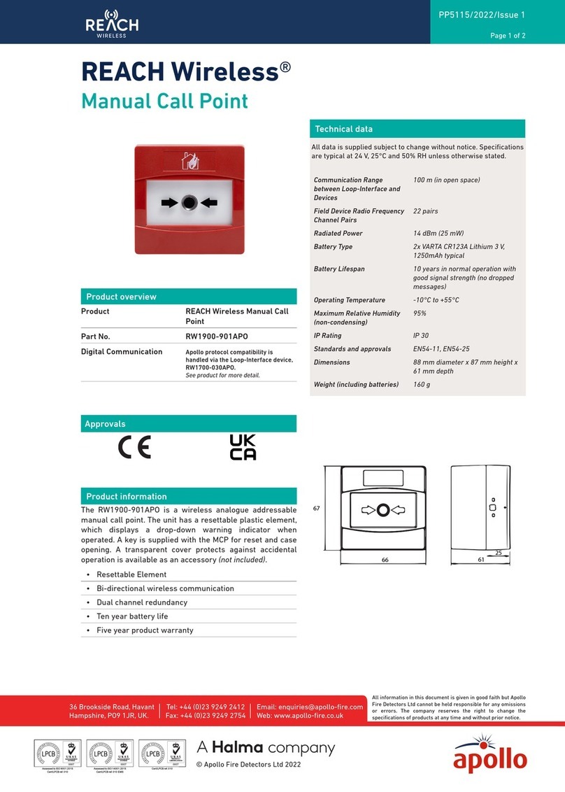
Apollo REACH WIRELESS RW1900-901APO User manual

Apollo
Apollo REACH WIRELESS RW1500-110APO User manual

Apollo
Apollo 55000-278 User manual
Apollo
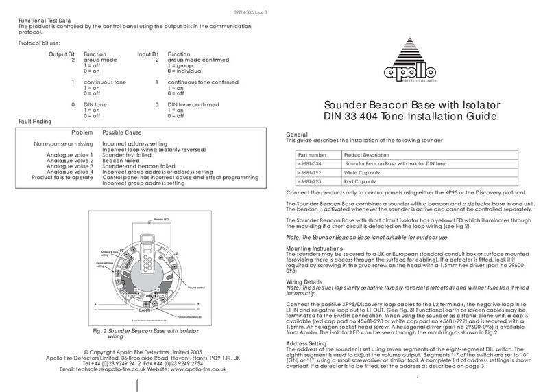
Apollo 33 404 Operating and maintenance instructions
Apollo
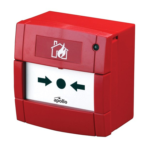
Apollo 55100-021 MAR User manual

Apollo
Apollo 55000-278 User manual
Apollo
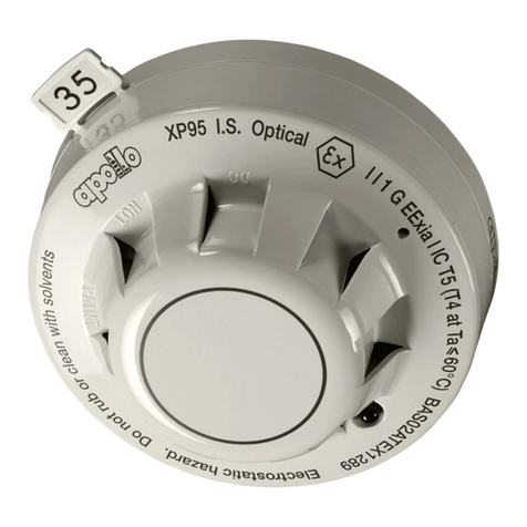
Apollo Smoke Detector XP95 Operating and maintenance instructions

Apollo
Apollo REACH WIRELESS RW1500-210APO User manual
Popular Security System manuals by other brands

Inner Range
Inner Range Concept 2000 user manual

Climax
Climax Mobile Lite R32 Installer's guide

FBII
FBII XL-31 Series installation instructions

Johnson Controls
Johnson Controls PENN Connected PC10 Install and Commissioning Guide

Aeotec
Aeotec Siren Gen5 quick start guide

IDEAL
IDEAL Accenta Engineering information

Swann
Swann SW-P-MC2 Specifications

Ecolink
Ecolink Siren+Chime user manual

Digital Monitoring Products
Digital Monitoring Products XR150 user guide

EDM
EDM Solution 6+6 Wireless-AE installation manual

Siren
Siren LED GSM operating manual

Detection Systems
Detection Systems 7090i Installation and programming manual

