Aprimatic PARK 30 Parts list manual

ES
DE
FR
EN
IT
PARK 40
PARK 60
Istruzioni per installazione uso e manutenzione
Instructions for installation, use and maintenance
Instructions d’installation et d’entretien
Installations, Gebrauchs und Wartungsanleitungen
Instrucciones para la instalación, el uso y el mantenimiento
Barriera veicolare automatica
Automatic vehicular barrier
Barrière automatique pour vèhicules
Automatische fahrzeugschranken
Barrera automática vehicular

Il libretto di INSTALLAZIONE USO E MANUTENZIONE è destinato agli installatori, agli utilizzatori ed agli operatori della manutenzione.
Leggere attentamente il libretto prima di installare il prodotto, utilizzarlo e prima di eseguire manutenzione ordinaria o straordinaria.
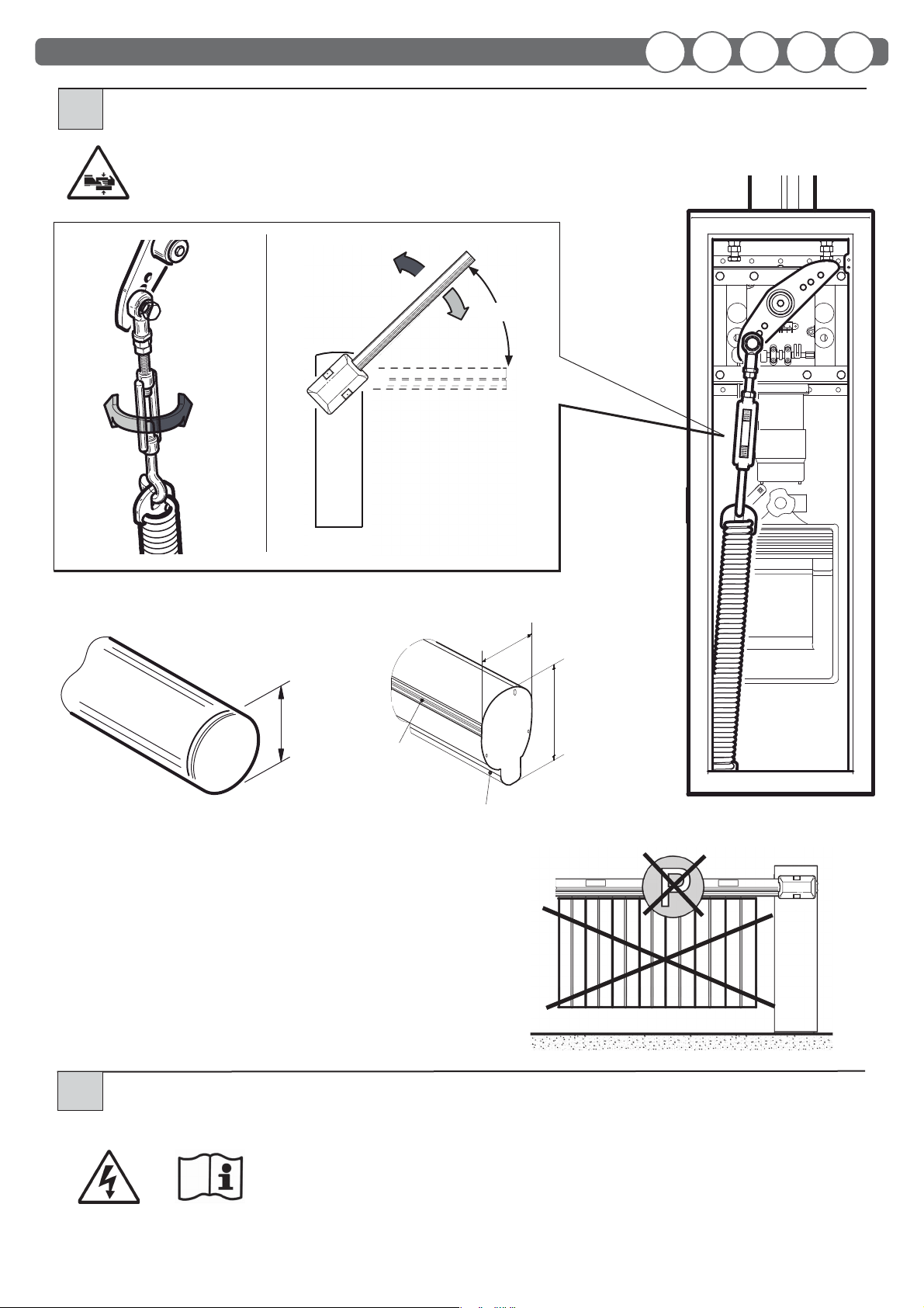
Le operazioni che, se non eettuate correttamente, possono presentare rischi, sono indicate con i simboli:
Il costruttore non è responsabile per danni arrecati a persone, animali o cose dovuti ad applicazioni che superano i limiti indicati nella scheda tecnica
allegata o dall’uso diverso da quello per cui il prodotto è stato progettato.
GENERALITÀ
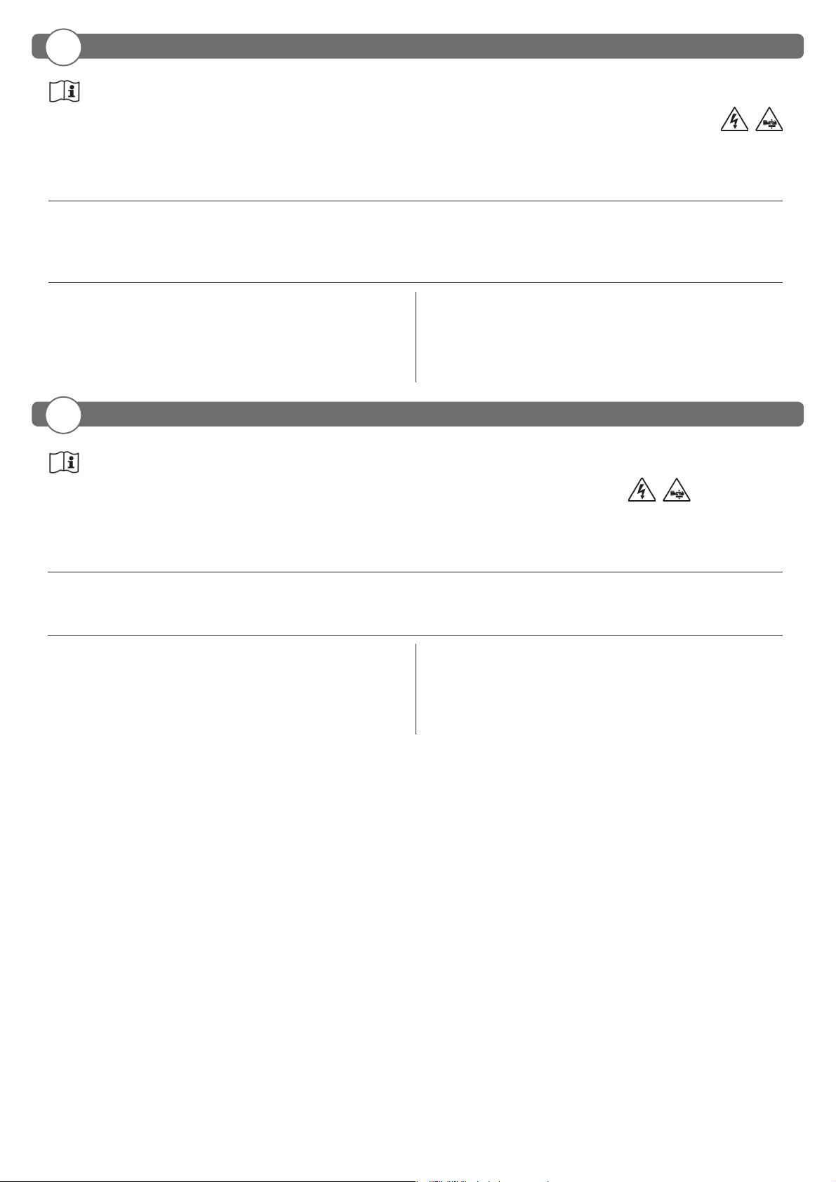
La barriera automatica elettromeccanica PARK 40 / 60 è stata progettata per gestire passaggi con luce fino a 6 metri nel rispetto delle normative
europee. E’ la soluzione ideale per la gestione veicolare. E’adatta ad un utilizzo di tipo residenziale e/o condominiale.
DATI TECNICI
Lunghezza barra............................................ H65: max 4
m (PARK 40);
5
m (PARK 60)
Ø80: max 6
m (PARK 60)
Temp. di esercizio......................................................................................................... -20 +60°C
Manovre in 24h........................................................................................................................1.000
Grado di protezione............................................................................................................... IP 54
Peso............................................................................................................................................~48 kg
Arm length....................................................H65: max 4 m (PARK 40); 5 m (PARK 60)
Ø80: max 6 m (PARK 60)
Working temp..............................................................................................................-20 +60°C
Manoeuvres in 24h ..............................................................................................................1.000
Protection level ...................................................................................................................... IP 54
Weight......................................................................................................................................~48 kg
Longueur de la lisse.................................H65: max 4 m (PARK 40); 5 m (PARK 60)
Ø80: max 6 m (PARK 60)
Température d’exercice ........................................................................................... -20 +60°C
Température d’exercice ......................................................................................................1.000
Indice de protection............................................................................................................ IP 54
Poids .........................................................................................................................................~48 kg
Alimentazione............................................................................230Vac ±10% 50/60 Hz
Motore 230Vac.................................................................................................. 24Vdc 70W
Potenza assorbita.........................................................................................................100 W
Centralina................................................................................................ TRAFFIC PARK 24
Sicurezza all’urto.....................................................................................Encoder (optical)
Tempo di apertura......................................2,5÷6
sec. (PARK 40); 4÷9
sec. (PARK 60)
Power.............................................................................................230Vac ±10% 50/60 Hz
Motor 230Vac.................................................................................................... 24Vdc 70W
Absorbed power...........................................................................................................100 W
Control unit ........................................................................................... TRAFFIC PARK 24
Impact safety............................................................................................ Encoder (optical)
Opening time..............................................2,5÷6
sec. (PARK 40); 4÷9
sec. (PARK 60)
Alimentation...............................................................................230Vac ±10% 50/60 Hz
Moteur 230Vac.................................................................................................. 24Vdc 70W
Puissance absorbée.....................................................................................................100 W
Centrale ................................................................................................... TRAFFIC PARK 24
Securite au choc ..................................................................................... Encoder (optical)
Delai d’ouverture.......................................2,5÷6
sec. (PARK 40); 4÷9
sec. (PARK 60)
The INSTALLATION, USE AND MAINTENANCE handbook is for installers, users and maintenance engineers.
Please read it carefully before installing the appliance, before using it and before routine or extraordinary maintenance work.
Operations that, if not carried out correctly, can be risky, are indicated with the following symbols:
The manufacturer is not liable for injury to people or animals or damage to things in the case of applications that exceed the limits specied on the
enclosed technical data sheet or by a use dierent from what the appliance has been designed.
GENERAL
The automatic electromechanical barrier PARK 40 / 60 is designed to control passage openings up to 6 metres wide in compliance with European
standards. It is the ideal solution for managing vehicle traffic. It is suitable for residential and/or condominium use.
TECHNICAL SPECIFICATIONS
Cette notice est destinée aux installateurs, aux utilisateurs et aux techniciens chargés de l’entretien.
Lisez attentivement cette notice, avant d’installer l’automatisme, de l’utiliser et avant de procéder à son entretien ordinaire ou extraordinaire.
Les opérations présentant des risques si elles ne sont pas eectuées correctement sont signalées avec les symboles:
Le fabribant décline toute responsabilité en cas de dégâts à des personnes, animaux ou biens provoqués par des applications dépassant les limites
prévues dans la che technique jointe ou par un usage diérent de celui pour lequel l’automatisme a été conçu.
GENERALITES
La lisse automatique électromécanique PARK 40 / 60 a été conçue pour gérer les passages jusqu’à une hauteur de 6 m dans le respect de la
législation européenne. Est la solution idéale pour contrôler le trafi c routier. Elle est adaptée à une utilisation de type résidentiel et/ou
de copropriétés.
DONNÉES TECHNIQUES
- 3 -
IT
EN
FR

Das INSTALLATIONS-, BETRIEBS- UND WARTUNGSHANDBUCH ist für die Installateure, Anwender und Wartungsfachmänner bestimmt.
Das Handbuch ist vor der Installation des Produkts sowie vor der ordentlichen und außerordentlichen Wartung sorgfältig zu lesen.
Wenn die durch folgende Symbole gekennzeichneten Eingrie nicht korrekt durchgeführt werden, kann es zu Gefahrsituationen kommen:
Die Firma Hersteller haftet nicht für Personen-, Tier- oder Sachschäden, die auf eine unsachgemäße Anwendung des Produkts sowie auf das Überschreiten
der im technischen Blatt angegebenen Grenzwerte zurückzuführen sind.
ALLGEMEINES
Die automatisch elektromechanische Schranke PARK 40 / 60 wurde für Durch und Einfahrten mit einer Breite von maximal 6 Metern entwickelt und
entspricht den EU-Normen. Es ist die ideale Lösung zum Verwalten des Straßenverkehrs.Die Schranke ist für den Einsatz in Wohnanlagen und/
oder Apartmenthäusern geeignet.
TECHNISCHE DATEN
Baumbreite..................................................H65: max 4 m (PARK 40); 5 m (PARK 60)
Ø80: max 6 m (PARK 60)
Betriebstemperatur ................................................................................................... -20 +60°C
Manöver in 24 std.................................................................................................................1.000
Schutzgrad................................................................................................................................ IP 54
Gewicht ...................................................................................................................................~48 kg
Longitud barra..........................................H65: max 4 m (PARK 40); 5 m (PARK 60)
Ø80: max 6
m (PARK 60)
Temp. de operación.................................................................................................. -20 +60°C
Maniobras en 24h.................................................................................................................1.000
Grado de protección ........................................................................................................... IP 54
Peso...........................................................................................................................................~48 kg
Stromversorgung ......................................................................230Vac ±10% 50/60 Hz
Motor 230Vac.................................................................................................... 24Vdc 70W
Leistungsaufnahme......................................................................................................100 W
Steuereinheit ......................................................................................... TRAFFIC PARK 24
Stossicherheit ........................................................................................... Encoder (optical)
Öffnungsdauer............................................2,5÷6
sec. (PARK 40); 4÷9
sec. (PARK 60)
Alimentación ..............................................................................230Vac ±10% 50/60 Hz
Motor 230Vac.................................................................................................... 24Vdc 70W
Potencia absorbida.....................................................................................................100 W
Centralita................................................................................................. TRAFFIC PARK 24
Seguridad al choque............................................................................. Encoder (optical)
Tiempo de apertura.................................2,5÷6
sec. (PARK 40); 4÷9
sec. (PARK 60)
El folleto de INSTALACIÓN, USO Y MANTENIMIENTO se destina a instaladores, usuarios y operadores de mantenimiento.
Leer detenidamente el folleto antes de instalar el producto, utilizarlo y efectuar el mantenimiento ordinario o extraordinario.
Las operaciones que, si no son efectuadas correctamente, pueden conllevar riesgos, vienen indicadas con los símbolos:
El fabricante no es responsable de daños causados a personas, animales o cosas, debidos a aplicaciones que superen los límites indicados en la cha
técnica adjunta o debidos a utilización diferente de aquella apra la cual el producto fue proyectado.
GENERALIDAD
La barrera automática electromecánica PARK 40 / 60 ha sido diseñada para controlar pasos con ancho de hasta 6 metros, según las normas europeas.
Es la solución ideal para la gestión del tráfico de vehiculos. Es apta para un uso de tipo residencial y/o de comunidad.
DATOS TÉCNICOS
- 4 -
DE
ES

DIMENSIONI D’INGOMBRO • OVERALL DIMENSIONS DIMENSIONS HORS-TOUT • ABMESSUNGEN • MEDIDAS
1
DISPOSIZIONE • LAYOUT •DISPOSITION • DISPOSITION • DISPOSICIÓN
2
Linea Monofase - Single-phase line - Ligne monophasée
Einphasenleitung - Línea monofásica 2 x 1,5 + T
Fotocellula Trasmett. - Transmitter photocell - Photocellule émettrice
Senderfotozelle - Fotocélula transmisor 2 x 0,5
Fotocellula Ricev. - Receiver photocell - Photocellule réceptrice
Empfängerfotozelle - Fotocélula receptor 4 x 0,5
Lampeggiante - Flashing light - Clignotant
Blinkleuchte - Indicador intermitente 2 x 0,5
Selettore a chiave - Key selector - Sélecteur à clé
Schlüsselschalter - Selector de llave 3 x 0,5
Ricevente - Receiver - Récepteur - Empfänger - Receptor 4 x 0,5
Antenna - Antenna - Antenne - Antenne - Antena RG58
Spirale magnetica - Magnetic coil - Spirale magnétique
Magnetspirale - Espiral magnética
5
6
3
1
2
4
6
7
- 5 -
2
5
7
3
1
2
4
6
START
ESDEFRENIT
Barriera DESTRA
RIGHT barrier
Lisse DROITE
RECHTE Schranke
Barrera DERECHA
Barriera SINISTRA
LEFT barrier
Lisse GAUCHE
LINKE Schranke
Barrera IZQUIERDA

FISSAGGIO STRUTTURA • FIXING THE STRUCTURE • FIXATION STRUCTURE STRUKTURBEFE-
STIGUNG • FIJACIÓN ESTRUCTURA
4
Regolare l’angolazione della struttura
Structure angling adjustment
Réglez l’angulation de la structure.
Den Strukturwinkel einstellen.
Ajustar la inclinación de la estructura
± 1,5°
Non fornito
Not supplied
Non fourni
Nicht mitgeliefert
No suministrada
CH 17
CH 13
Ø50
Direzione traco
Direction of trac
Direction du trac
Fahrtrichtung
Dirección tráco
BASAMENTO • BASE • BASE • BASIS • BASE
3
400
500
320
500
220
- 6 -
IT EN FR DE ES

GREASE
H65
4,8x13
Rimuovere la pellicola protettiva
lm
lm protecteur
lm
Quite la película protectora
Ø80
4,8x13
M8
Ø8
M6x20
Ø8
M8x25
Ø8
M8x25
ASSEMBLAGGIO BARRA • MOUNTING THE ARM • ASSEMBLAGE LISSE • BAUMZUSAMMENBAU • MONTAJE BARRA
5
Montaggio barra e regolazione necorsa su barriera SINISTRA
Mounting the arm and adjusting the limit switch on the LEFT barrier
Montage lisse et réglage n de course sur lisse GAUCHE
Baummontage und Endschaltereinregulierung an LINKER Schranke
Montaje barra y ajuste nal de carrera en barrera IZQUIERDA
FCC
necorsa di chiusura
closing limit switch
n de course de fermeture
Endanschlag Schliessen
nal de carrera cierre
FCA
Finecorsa di apertura
Opening limit switch
Fin de course ouverture
Endanschlag Önen
Final carrera apertura
REGOLAZIONE FINECORSA • ADJUSTING THE LIMIT SWITCH • REGLAGE FIN DE COURSE
EINREGUILIERUNG DES ENDANSCHLAGS • AJUSTE FINAL DE CARRERA
6
FCC FCA
- 7 -
ESDEFRENIT

Barriera DESTRA
RIGHT barrier
Lisse DROITE
RECHTE Schranke
Barrera DERECHA
MONTAGGIO MOLLA • ASSEMBLING THE SPRING • MONTAGE RESSORT • FEDERMONTAGE• MONTAJE MUELLE
7
Barriera SINISTRA
LEFT barrier
Lisse GAUCHE
LINKE Schranke
Barrera IZQUIERDA
MANOVRA MANUALE • MANUAL MANOEUVRE • MANOEUVRE MANUELLE • MANUELLES MANÖVRIEREN
MANIOBRA MANUAL
Sbloccaggio barriera
Releasing the barrier
Déblocage de la lisse
Schranke entsperren
Desbloqueo barrera
Bloccaggio barriera
Locking the barrier
Blocage de la lisse
Schranke sperren
Bloqueo barrera
90°
90°
Prima di eettuare qualsiasi intervento sull’impianto togliere l’alimentazione elettrica.
Always disconnect the electricity before attempting any work on the system.
Coupez l’arrivée de courant électrique avant toute intervention sur l’automatisme.
Vor jeglichen Eingrien an der Anlage ist die Stromversorgung zu unterbrechen.
Antes de cualquier operación en la instalación, cortar la alimentación eléctrica.
Ø12
Ø12
M12x35
8
L
L= 5÷6m
L= 3m
L= 4m
- 8 -
IT EN FR DE ES

45°÷50°
-+
Ø80
KIT LED
KIT-GOMA
Non appesantire la barra applicando altri accessori
Do not weigh the arm down by applying other accessories
Ne pas alourdire la lisse en y appliqant d’autres accessoires
Den Baum nicht durch die Installation von weiterem Zubehör belasten
No aumentar el peso de la barra poniendo otros accesorios
60
79
EQUILIBRATURA DELLA BARRA • BALANCING THE ARM • EQUILIBRAGE DE LA LISSE
AUSBILANCIERUNG DES BAUMES • EQUILIBRADO DE LA BARRA
9
COLLEGAMENTI ELETTRICI • ELECTRICAL CONNECTIONS • BRANCHEMENTS ELECTRIQUES
ELEKTRISCHE ANSCHLÜSSE • CONEXIONES ELÉCTRICAS
10
•Consultare il manuale d’installazione e uso della centralina TRAFFIC PARK 24
•
Consult the TRAFFIC PARK 24 control unit’s installation and operating manual
•Consulter le manuel d’installation et d’utilisation de la centrale TRAFFIC PARK 24
•Die Installations und Bedienungsanleitungen der Steuereinheit TRAFFIC PARK 24 nachschlagen.
•Consultar el manual de instalación y uso de la centralita TRAFFIC PARK 24
- 9 -
ESDEFRENIT

SICUREZZA GENERALE
• Si consiglia, per ragioni di sicurezza e nel rispetto delle normative vigenti, di utilizzare l’apposita centralina di comando.
• L’installazione deve essere eseguita seguendo le prescrizioni contenute nel foglio allegato “AVVERTENZE GENERALI PER LA SICUREZZA”.
• I collegamenti elettrici devono essere eettuati nel rispetto delle disposizioni legislative vigenti.
• L’installatore deve istruire l’utilizzatore sul corretto funzionamento dell’automatismo, sulla manovra manuale d’emergenza e sui possibili rischi durante il
funzionamento.
• Eseguire l’analisi dei rischi prendendo opportuni provvedimenti per eliminarli, come prescritto dalla direttiva macchine 2006/42/CEE, installando i dispositivi
di sicurezza.
• Prima di eettuare qualsiasi intervento sull’impianto togliere l’alimentazione elettrica mediante un sezionatore lucchettabile.
USO
• Seguire tassativamente le indicazioni contenute nel foglio allegato “AVVERTENZE GENERALI PER LA SICUREZZA”.
• In caso di manovra manuale seguire le indicazioni descritte al punto 8.
MANUTENZIONE ORDINARIA
(OGNI SEI MESI)
• La manutenzione deve essere eseguita solo da personale qualicato.
• Controllare lo stato della struttura della barriera.
• Controllare lo stato del serraggio barra.
• Controllare lo stato della molla e dei relativi ancoraggi.
• Controllare l’equilibratura della barra.
• Controllare che a necorsa la barra sia orizzontale e/o verticale
• Vericare il funzionamento della manovra di emergenza.
• Vericare il funzionamento della centralina e dei dispositivi di sicurezza.
GENERAL SAFETY
• For safety reasons and to comply with current standards, we recommend using the control unit.
• To install follow the instructions given in the enclosed“GENERAL INSTRUCTIONS FOR SAFETY” sheet.
• All electrical connections must be done in compliance with current laws.
• The installer must instruct the user on how to use the automatism correctly, on the manual emergency manoeuvre and on the possible risks during operation.
• Analyse the risks and take all the appropriate measures to eliminate them, as prescribed by the EEC machine directive 2006/42, installing the safety devices.
• Always disconnect the electricity before attempting any work on the system with a lockable cut-o switch.
USE
• It is essential to follow the instructions given in the enclosed“GENERAL INSTRUCTIONS FOR SAFETY” sheet.
• In the case of a manual manoeuvre, follow the indications described in point 8.
ROUTINE MAINTENANCE
(EVERY 6 MONTHS)
• Maintenance must be carried out by qualied personnel only.
• Check the condition of the barrier structure.
• Check tightness of the arm.
• Check the condition of the spring and relative anchorings.
• Check arm balance.
• Check that at the end of travel the arm is horizontal and/or vertical
• Check operation of the emergency manoeuvre.
• Check operation of the control unit and safety devices.
- 10 -
IT
EN

SECURITE GENERALE
• Pour des raisons de sécurité et d’observation de la législation en vigueur, il est conseillé d’utiliser la centrale de commande .
• La pose doit s’eectuer selon les prescriptions reportées sur la feuille jointe “REGLES GENERALES DE SECURITE”.
• Les branchements électriques doivent être conformes à la législation en vigueur en la matière.
• L’installateur doit informer l’utilisateur sur le fonctionnement de l’automatisme, sur la manœuvre manuelle d’arrêt d’urgence et sur les risques liés au
fonctionnement.
• L’analyse des risques implique la mise sur pied de mesures destinées à éliminer lesdits risques comme le prévoit la directive machines 2006/42/CEE, en installant
les dispositifs de sécurité.
• Coupez l’arrivée de courant électrique avant toute intervention sur l’automatisme avec un interrupteur verrouillable.
UTILISATION
• Suivez scrupuleusement les prescriptions reportées sur la feuille jointe “REGLES GENERALES DE SECURITE”.
• En cas de manœuvre manuelle, suivez les indications décrites au paragraphe 8.
ROUTINE MAINTENANCE
(TOUS LES 6 MOIS)
• L’entretien doit être eectué seulement par un personnel qualié.
• Contrôlez la structure de la lisse.
• Contrôlez le serrage de la lisse.
• Contrôlez l’état du ressort et des xations correspondantes.
• Contrôlez l’équilibrage de la lisse.
• Contrôlez l’horizontalité et/ou la verticalité de la lisse en n de course.
• Vériez le fonctionnement de la manœuvre d’urgence.
• Vériez le fonctionnement de la centrale et des dispositifs de sécurité.
ALLGEMEINE SICHERHEIT
• Aus Sicherheitsgründen und zum Einhalten der anwendbaren Gesetze wird empfohlen, die spezielle Steuereinheit von zu verwenden.
• Bei der Installation sind die im beiliegenden Blatt “ALLGEMEINE SICHERHEITSHINWEISE”enthaltenen Vorschriften zu befolgen.
• Beim Anschluss an die Stromversorgung sind die geltenden Gesetze zu befolgen.
• DerInstallateurhat denAnwenderbezüglich des korrekten Betriebsdes Automatismus,der manuellenBedienung beiStörungen undNotfällen sowiebezüglich
der möglichen Gefahren während des Betriebs zu unterrichten.
• Es ist eine Gefahrenanalyse durchzuführen und es sind geeignete Maßnahmen zum Eliminieren der Gefahren zu treen, wie von der Maschinenrichtlinie
2006/42/EWG vorgeschrieben, wobei auch der Schub einreguliert und die erforderlichen Sicherheitsvorrichtungen installiert werden müssen.
• Vor jeglichen Eingrien an der Anlage ist die Stromversorgung mit einen Schlüssel-Trennschalter zu unterbrechen.
BETRIEB
• Die in dem beigestellten Blatt“ALLGEMEINE SICHERHEITSVOR-SCHRIFTEN”enthaltenen Anleitungen sind strikt zu befolgen.
• Beim manuellen Manövrieren sind die unter Punkt 8 beschriebenen Anleitungen zu beachten.
ORDENTLICHE WARTUNG
(ALLE 6 MONATE)
• Die Wartung hat ausschließlich durch Fachpersonal zu erfolgen.
• Zustand der Schrankenstruktur überprüfen.
• Kontrollieren, dass der Baum korrekt befetsigt ist.
• Zustand der Feder und der entsprechenden Verankerungen überprüfen.
• Ausbilancierung des Baumes überprüfen.
• Kontrollieren, dass der Baum am Endanschlag waagerecht oder senkrecht ist.
• Funktionstüchtigkeit des Notmanövers überprüfen..
• Funktionstüchtigkeit der Steuereinheit und der Sicherheitsvorrichtungen überprüfen.
- 11 -
FR
DE

- 12 -
cod. 035712-A rev. 003 date 17-02-2015
INSTALLATORE
INSTALLER
INSTALLATEUR
INSTALLATEUR
INSTALADOR
SEGURIDAD GENERAL
• Por razones de seguridad y para respetar las normas vigentes se aconseja utilizar la correspondiente centralita de control.
• La instalación debe efectuarse siguiendo las prescripciones presentadas en la hoja adjunta“ADVERTENCIAS GENERALES PARA LA SEGURIDAD”.
• Las conexiones eléctricas deben efectuarse cumpliendo las disposiciones de ley vigentes.
• El instalador debe instruir al usuario sobre el funcionamiento correcto del automatismo, maniobra manual de emergencia y posibles riesgos durante el
funcionamiento.
• Efectuarel análisisde riesgostomando lasoportunas medidaspara eliminarlos, comoprescrito porla directiva máquina2006/42/CEE, instalandolos dispositivos
de seguridad.
• Antes de cualquier operación en la instalación, cortar la alimentación eléctrica con un interruptor seccionador.
USO
• Seguir tajantemente las indicaciones presentadas en la hoja adjunta“ADVERTENCIAS GENERALES PARA LA SEGURIDAD”.
• En caso de maniobra manual seguir las indicaciones del punto 8.
MANTENIMIENTO ORDINARIO
(CADA 6 MESES)
• El mantenimiento debe ser efectuado sólo por personal cualicado.
• Comprobar el estado de la estructura de la barrera.
• Comprobar el estado del apriete de la barra.
• Comprobar el estado del muelle y correspondientes jaciones.
• Comprobar el equilibrio de la barra.
• Comprobar que a tope de carrera la barra quede horizontal y/o vertical
• Vericar el funcionamiento de la maniobra de emergencia.
• Vericar el funcionamiento de la centralita y de los dispositivos de seguridad.
ES
This manual suits for next models
3
Table of contents
Other Aprimatic Automatic Barrier manuals