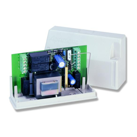
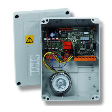
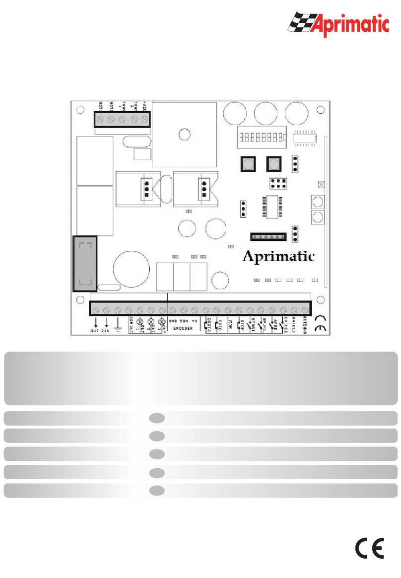
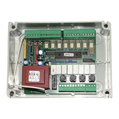
Aprimatic Onda 424 Quick start guide

Apparecchiatura di controllo
Istruzioni di installazione elettrica Uso e
Manutenzione
Electrical installation, Use and Maintenance
instructions
Notice d’installation éléctrique, d'Utilisation
et d’Entretien
Anleitung für die elektrische Installation,
Gebrauch und Wartung
Instrucciones para la instalación electrica, el
uso y el mantenimiento
BUT DU MANUEL
Ce manuel a été rédigé par le constructeur et fait partie intégrante du produit.
Il contient toutes les informations nécessaires pour :
• sensibiliser les installateurs aux problèmes liés à la sécurité ;
• installer le dispositif de manière correcte ;
• connaître le fonctionnement et les limites du dispositif ;
• utiliser correctement le dispositif dans des conditions de sécurité optimales ;
Lerespectdesindicationsfourniesdanscemanuelgarantitlasécuritépersonnelle,uneéconomiedefonctionnement
et une longue durée de vie du produit.
Afin d’éviter des opérations incorrectes et de ne pas risquer des accidents sérieux, lire attentivement ce manuel et
respecter scrupuleusement les informations fournies.
Lesinstructions,lesdessins,lesphotosetladocumentationcontenusdanscemanuelsontlapropriétéd’APRIMATIC
S.p.A. et ne peuvent être reproduits sous aucune forme, ni intégralement, ni partiellement.
Le logo « Aprimatic » est une marque déposée parAprimatic S.p.A.
OBJETO DEL MANUAL
Este manual ha sido redactado por el constructor y forma parte integrante del producto.
El mismo contiene todas las informaciones necesarias para:
• la correcta sensibilización de los instaladores hacia los problemas de la seguridad
• la correcta instalación del dispositivo
• el conocimiento en profundidad de su funcionamiento y de sus límites
• el correcto uso en condiciones de seguridad
La constante observación de las indicaciones suministradas en este manual, garantiza la seguridad del hombre,
la economía del ejercicio y una mayor duración de funcionamiento del producto.
Con el fin de evitar maniobras equivocadas con riesgo de accidente, es importante leer atentamente este manual,
respetando escrupulosamente las informaciones suministradas.
Las instrucciones, los dibujos, las fotografías y la documentación que contiene este manual son propiedad de
APRIMATIC S.p.a. y no pueden ser reproducidas en ninguna manera, ni integral ni parcialmente.
El logotipo “Aprimatic” es una marca registrada de Aprimatic S. p.A.
ZWECK DES HANDBUCHS
Dieses Handbuch wurde vom Hersteller verfasst und ist ein ergänzender Bestandteil des Produkts.
Es enthält alle nötigen Informationen für:
• die Sensibilisierung der Monteure für Fragen der Sicherheit;
• die vorschriftsmäßige Installation der Vorrichtung;
• die umfassende Kenntnis ihrer Funktionsweise und ihrer Grenzen;
• die vorschriftsmäßige und sichere Benutzung.
Die Beachtung der in diesem Handbuch enthaltenen Anweisungen gewährleistet die Sicherheit der Personen, den
wirtschaftlichen Betrieb und eine lange Lebensdauer des Produkts.
Zur Vermeidung von Fehlbedienung und somit Unfallgefahr dieses Handbuch aufmerksam durchlesen und die
Anweisungen genau befolgen.
Die Anleitungen, Zeichnungen, Fotos und Dokumentationen in diesem Handbuch sind Eigentum von APRIMATIC
S.p.A. und dürfen in keiner Weise ganz oder teilweise reproduziert werden.
Das Logo „Aprimatic“ ist ein eingetragenes Warenzeichen der Aprimatic S. p. A.
PURPOSE OF THE MANUAL
This manual was drawn up by the manufacturer and is an integral part of the product.
It contains all the necessary information:
• to draw the attention of the installers to safety related problems
• to install the device properly
• to understand how it works and its limits
• to use the device under safe conditions
Strict observance of the instructions in this manual guarantees safe conditions as well as efficient operation and
a long life for the product.
To prevent operations that may result in accidents, read this manual and strictly obey the
instructions provided.
Instructions, drawings, photos and literature contained herein are the exclusive property of the
manufacturer and may not be reproduced by any means.
The “Aprimatic” logo is a trademark registered by Aprimatic S.p.A.
SCOPO DEL MANUALE
Questo manuale è stato redatto dal costruttore ed è parte integrante del prodotto.
In esso sono contenute tutte le informazioni necessarie per:
• la corretta sensibilizzazione degli installatori alle problematiche della sicurezza;
• la corretta installazione del dispositivo;
• la conoscenza approfondita del suo funzionamento e dei suoi limiti;
• il corretto uso in condizioni di sicurezza;
La costante osservanza delle indicazioni fornite in questo manuale, garantisce la sicurezza dell’uomo, l’economia
di esercizio e una più lunga durata di funzionamento del prodotto.
Al fine di evitare manovre errate con il rischio di incidenti, è importante leggere attentamente questo manuale,
rispettando scrupolosamente le informazioni fornite.
Le istruzioni, i disegni, le fotografie e la documentazione contenuti nel presente manuale sono di proprietà
APRIMATIC S.p.a. e non possono essere riprodotti in alcun modo, né integralmente, né parzialmente.
Il logo “APRIMATIC” è un marchio registrato di APRIMATIC S.p.a.
Italiano
EnglishFrançaisDeutschEspañol
Control unit
Platine de commande
Steuereinheit
Equipo de control
ONDA 424/ ONDA 624
cod. LBT0066 - luglio 08

- 2-
ONDA 424/ONDA 624
APPARECCHIATURE DI CONTROLLO
Italiano
SOMMARIO
Norme di sicurezza e obblighi dell’installatore 3
Avvertenze per l’utilizzatore 3
Terminologia e simboli Adottati nel manuale 3
1. Descrizione del prodotto 4
1.1 Uso previsto e Limiti d’impiego .........................................................................................................4
1.2 Caratteristiche...................................................................................................................................4
1.3 Dati tecnici.........................................................................................................................................4
2. Installazione 3
2.1 Collegamenti elettrici.........................................................................................................................4
2.2 Schema di Predisposizione allacciamenti elettrici.............................................................................5
2.3 Schema dell'apparecchiatura............................................................................................................6
3. Controlli e regolazioni 7
3.1 Verifica senso di marcia del motore e del cancello...........................................................................7
3.2 Apprendimento telecomandi .............................................................................................................7
3.3 Apprendimento della corsa di apertura e della forza di spinta del cancello......................................7
3.4 Apprendimento della corsa pedonale................................................................................................7
3.5 Regolazione della soglia di massima coppia ....................................................................................8
3.6 Verifica del funzionamento dei finecorsa...........................................................................................8
3.7 Modalità e Tempo di richiusura .........................................................................................................8
3.8 Verifica fotocellule.............................................................................................................................8
3.9 Cancellazione totale della memoria..................................................................................................8
4. Note per l'utente e il manutentore 9
4.1 Manutenzione programmata.............................................................................................................9
4.2 Ricerca guasti ...................................................................................................................................9

- 3-
ONDA 424/ONDA 624 APPARECCHIATURE DI CONTROLLO
Italiano
NORME DI SICUREZZA E OBBLIGHI DELL’INSTALLATORE
Per lavorare nel pieno rispetto delle norme di sicurezza occorre:
• indossare indumenti di protezione a norma di legge (scarpe antinfortunistiche, occhiali di protezione, guanti ed elmetto);
• non indossare articoli di abbigliamento che possano impigliarsi (cravatte, bracciali, collane, ecc.).
Uncancelloautomaticoèunamacchinaedeveessereinstallatasecondoquantoprevistodalleleggi,lenormeeiregolamentiinvigore.
Prima dell’installazione deve essere effettuata l’analisi dei rischi sul sito da parte di persone professionalmente qualificate
secondo le leggi in vigore per le chiusure motorizzate. Per ottenere un livello di sicurezza adeguato, l’installazione deve
essere eseguita secondo quanto previsto dalle Norme EN 12453 e EN 12445. Nei Paesi extra CEE, oltre alle Norme citate,
fare riferimento a leggi e normative nazionali.
• L’installazione deve essere eseguita da persone professionalmente qualificate.
•L’installazione,icollegamentielettricieleregolazioninecessariedevonoessereeffettuatisecondoleleggielenormeinvigore.
• Leggere attentamente le istruzioni prima di procedere all’installazione.
• Una non corretta installazione può essere fonte di pericoli.
•Gliimballinondevonoessereabbandonatinell’ambiente,madevonoesseresmaltitisecondoleleggiediregolamentiinvigore.
• Prima di iniziare l’installazione verificare che il prodotto e l’imballo non siano danneggiati.
• Non installare il prodotto in aree dove vi sia il rischio di esplosione: la presenza di gas, polveri o fumi infiammabili
rappresenta una seria minaccia per la sicurezza.
• Verificare che vi siano tutti i franchi di sicurezza e che tutte le zone in cui vi sono rischi di schiacciamento, cesoiamento o
intrappolamentoocomunquepericolose sianosalvaguardateoprotettesecondole normeinvigoreperi cancelli motorizzati.
• Obbligo di delimitare opportunamente la zona di intervento per evitare l’accesso di persone estranee.
• I dispositivi di protezione devono essere installati in seguito ad una analisi dei rischi sul luogo, verificando che siano
marchiati e funzionino secondo le norme in vigore.
• Su ogni installazione devono essere riportati in modo visibile i dati richiesti dalle norme applicabili.
• Prima di collegarsi alla linea di alimentazione verificare che la potenza disponibile sia coerente con i dati di targa.
Verificare che a monte dell’installazione sia presente un interruttore magnetotermico differenziale adeguato.
• Il produttore della motorizzazione declina ogni responsabilità qualora vengano utilizzati componenti non compatibili con
un corretto e sicuro utilizzo.
• L’installatore deve fornire all’utilizzatore tutte le necessarie informazioni sull’utilizzo dell’automazione con particolare
riguardo alle procedure per la manovra manuale di emergenza e ad eventuali rischi residui.
AVVERTENZE PER L’UTILIZZATORE
•Leindicazioni e avvertenzecheseguonosono parteintegraleedessenziale delprodotto.Essedevono essere consegnate
all’utilizzatoree devono esserelette attentamentepoiché contengono importantiavvertimenti perl’uso e lamanutenzione.
Queste istruzioni devono essere conservate e consegnate a tutti i futuri possibili utilizzatori.
•Questaautomazionedeveessereutilizzataesclusivamenteperl’usocuièdestinata.Ognialtroutilizzoèimproprioepericoloso.
• Evitare di sostare nei pressi delle parti meccaniche in movimento. Non entrare nel raggio d’azione dell’automazione in
movimento. Non tentare di ostacolare od ostruire il movimento dell’automazione perché può essere fonte di pericolo.
• Non permettere ai bambini di giocare o sostare nel raggio d’azione dell’automazione.
• Tenere sotto controllo i radiocomandi o altri dispositivi di attivazione del movimento in modo da evitare azionamenti
involontari da parte di bambini o estranei.
•Incasodiguasto o funzionamentononregolare,toglierealimentazionedell’automazione azionando l’interruttoreprincipale.
Non tentare di intervenire o di riparare l’unità principale e contattare chi ha installato l’automazione o un altro installatore
specializzato. Non rispettare questo avvertimento può portare a situazioni di pericolo.
• Tutte le operazioni di riparazione e di manutenzione, incluse quelle di pulizia dell’azionamento, devono essere effettuate
solamente da persone qualificate.
• Per garantire un corretto ed efficiente funzionamento è necessario seguire le istruzioni del produttore e in particolare
fare effettuare una manutenzione periodica da personale specializzato che verifichi soprattutto il regolare funzionamento
dei dispositivi di protezione.
•Tutteleriparazionielemanutenzionieseguitedevonoessereregistratesulregistrodimanutenzioneeresedisponibiliperl’utilizzatore.
TERMINOLOGIA E SIMBOLI ADOTTATI NEL MANUALE
• ZONA D’INTERVENTO
zona che circoscrive l’area in cui si esegue l’installazione e dove la presenza di una persona esposta
costituisce un rischio per la sicurezza e la salute della persona stessa (Allegato I, 1.1.1 Direttiva 89/392/CEE);
• PERSONA ESPOSTA qualsiasi persona che si trovi interamente o in parte in una zona pericolosa (Allegato I, 1.1.1
- Direttiva 89/392/CEE);
• INSTALLATORE persona incaricata di installare, far funzionare, regolare, eseguire la manutenzione, pulire, riparare e
trasportare il dispositivo (Allegato I, 1.1.1 - Direttiva 89/392/CEE);
•
PERICOLO RESIDUO pericolo che non è stato possibile eliminare o sufficientemente ridurre attraverso la progettazione.
Attenzione
!
Leindicazioniprecedutedaquestosimbolocontengonoinformazioni,prescrizionioprocedurechese
noneseguitecorrettamentepossonocausarelesioni,morteorischialungotermineperlasalutedellepersoneeperl’ambiente.
Cautela
Leindicazioniprecedutedaquestosimbolocontengonoprocedureopraticheche,senoneseguite
correttamente, possono causare gravi danni alla macchina o al prodotto.
Informazioni
Le indicazioni precedute da questo simbolo contengono informazioni su qualsiasi soggetto di
particolare importanza: il loro mancato rispetto può comportare la perdita della garanzia contrattuale.

- 4-
ONDA 424/ONDA 624
APPARECCHIATURE DI CONTROLLO
Italiano
DESCRIZIONE DEL PRODOTTO1.
Uso previsto e limiti d’impiego1.1
Questaapparecchiaturaèstataprogettataperilcontrollodegli
operatori per cancelli scorrevoli
ONDA424
e
ONDA624
.
Qualsiasi altro impiego non è autorizzato da
Aprimatic
.
Cautela
Èvietatoutilizzareilprodottoperscopiimpropriocomunque
diversi da quelli previsti.
È vietato manomettere o modificare il prodotto.
Il prodotto deve essere installato solo con accessori
APRIMATIC.
Caratteristiche1.2
• L’apparecchiatura è dotata di una funzione che a ogni
movimento del cancello andata a buon fine (quindi senza
l’intervento di nessun allarme) esegue un’autotaratura. In
questo modo eventuali variazioni lente delle condizioni
dell’installazione possono essere assorbite di volta in
volta.
• In fase di installazione, la prima volta che si movimenta
completamente il cancello, prestare particolare attenzione
in quanto l’apparecchiatura esegue questa prima fase con
una soglia di valore elevato per impostare correttamente i
valori di intervento dell’allarme.
Evitare durante questa fase di eseguire modifiche o prove
sull’installazione, in quanto si potrebbe pregiudicarne una
corretta impostazione.
• Inoltre ad ogni riaccensione in seguito a una mancanza
di tensione, al primo comando impartito l’apparecchiatura
comanda una richiusura a velocità ridotta fino a completa
chiusura del cancello, in modo da riportarsi sul finecorsa
di chiusura.
Dati tecnici1.3
Vedi tabella.
INSTALLAZIONE2.
Collegamenti elettrici2.1
Terminata l’installazione meccanica, occorre completare
correttamente l’installazione elettrica, rispettando tutte le
Tab. Dati tecnici
Tensione di alimentazione monofase 230V 50Hz
±6%
Potenza max assorbita 80W
Corrente max alimentazione accessori 200 mA
Temperature di funzionamento -25 / +55 °C
Grado di protezione IP 44
Motore elettrico 24 V DC
indicazioni di seguito fornite.
Attenzione
!
Prima di effettuare il collegamento elettrico è essenziale leggere i paragrafisuccessivi relativi
all’apparecchiatura elettronica di comando e attenersi ad essi.
I collegamenti elettrici con gli accessori (fotocellule, lampeggiatore etc.) vanno effettuati come indicato nello SCHEMA
DELL'APPARECCHIATURAe tenendo in considerazione le specifiche istruzioni fornite a corredo di ciascuno.
Si raccomanda di utilizzare cavi adeguati all’utilizzo (vedi
SCHEMA DI PREDISPOSIZIONE ALLACCIAMENTI ELETTRICI)
per le sezioni minime da utilizzare.
È OBBLIGATORIALA MESSAATERRADELLE MASSE METALLICHE DELLASTRUTTURA(CANCELLO E PILASTRI).
Attenzione
!
Prima del collegamento elettrico scollegare la linea di alimentazione dell’apparecchiatura dalla rete.
Proteggerel’alimentazionetramite un interruttoreautomaticodifferenziale6Aconsogliadiintervento 30 mA(vediSchema
di Predisposizione allacciamenti elettrici).
I collegamenti e la manutenzione devono essere eseguiti solo ed esclusivamente da personale qualificato e nell’assoluto
rispetto delle norme vigenti.
Fissare il cavo di alimentazione per evitare eventuali trazioni o torsioni nei punti di collegamento ai morsetti.
I dispositivi accessori di controllo e comando e il pulsante di emergenza devono essere collocati entro il campo visivo
dell’automazione, lontano da parti in movimento e a un’altezza minima da terra di 1,5m.

- 5-
ONDA 424/ONDA 624 APPARECCHIATURE DI CONTROLLO
Italiano
Aprimatic
9
6A
lc= 30mA
230 VAC
A
r
i
m
a
ti
c
p
A
r
i
m
a
ti
c
p
123456789101112 12 13
3
5
d
cb
e
a
d
4
6
e
24
1
1
apparecchiatura di controllo................... a2 x 1,5 mm2+ terra
2
antenna 433,92 MHz..............................ccavo in dotazione
3
lampeggiante.......................................... d2 x 1 mm2
4
coppia di fotocellule................................ eemettitrice 2 x 0,75 mm2; ricevente 4 x 0,75 mm2
5
selettore a chiave................................... f3 x 0,75 mm2
6
dispositivi di comando OPZIONALI........ f3 x 0,75 mm2
Lettore di prossimità* , Lettore di scheda* , Combinatore a tastiera*
7
telecomando * accessorio opzionale (consultare il catalogo di vendita)
Schema di Predisposizione impianto elettrico2.2
AVVERTENZE:
• MOTORE ELETTRICO ED ENCODER: sono collegati in
produzione tramite il connettore a 5 poli.
• LAMPEGGIANTE
: è prevista l’utilizzazione del
lampeggiante
ET2
N
Aprimatic
a LED (morsetti 1 -2).
N.B.: Non utilizzare altri modelli.
• FOTOCELLULE: vedere lo schema di collegamento
specifico
(vedi Figura a lato o istruzioni della fotocellula).
N.B.: In caso di mancanza di fotocellule ponticellare i
morsetti 5 - 9 della scheda.
•
PULSANTE ACHIAVE: collegare il contatto
N.O. tra il 5-11.
• PULSANTE DI STOP: collegare il contatto NC tra il 5-8.
N.B.:
in casodi mancanzadel pulsantedi Stopponticellare
il 5-8.
•FINECORSA:il gruppofinecorsaègià collegato,verificare
l’intervento del finecorsa e invertire eventualmente i
collegamenti 6-7, in base al senso di marcia.
2
1+
-
+ 24V
-
3
4
5+
-
5
4
3
2
1
9
Collegamento Fotocellule
APRIMATIC
ER2N - ER4N
morsettiera a 13 poli
sull'apparecchiatura
TRASMITTENTE RICEVENTE

- 6-
ONDA 424/ONDA 624
APPARECCHIATURE DI CONTROLLO
Italiano
Schema dell'apparecchiatura2.3
Cautela
Per accedere all’apparecchiatura rimuovere il coperchio in plastica trasparente e rimontarlo al termine delle operazioni.
TR1 TR2
Impostazione soglia massima coppia
Richiusura automatica
Manuale
S1
Automatico
MODULO MEMORIA
LED POWER
BATT.1 12V 1,3Ah
LED BLINK-LIGHT
Selettore manuale / automatico
ANTENNA
Calza antenna
123
GIALLO BLU ROSSO
Modulo radio
LAMPEGGIANTE
ENCODER
+5VDC
GND
SEGNALE
MOTORE
24VDC 100mA Max
POSITIVO alim. FOTOC.
trasmittente e ricevente
NEGATIVO alim. fotoc. TRASMITT.
NEGATIVO alim. fotoc. RICEV.
e COMUNE ingressi
123456789101112
ALIMENTAZIONE
24 VAC
ALIMENTAZIONE RETE 230V 50Hz
FN
F1
TRA
Connettore
Caricabatteria
Connettore Motore
BATT.2 12V 1,3Ah
Reversing Motor
Carica Batteria (OPTIONAL)
1
2
MIN MAX
1
2
3
START (Passo / Passo)
Contatto fotocellula
Stop
Finecorsa apertura
Finecorsa chiusura
STARTApertura pedonale
CONNETTORE
RX Aprimatic
Modulo Radioricevente
(OPZIONALE)
12 13
+-
Per il cambio del senso
di marcia del motore,
attenersi a quanto
descritto nel paragrafo
“VERIFICASENSO DI
MARCIADEL
MOTORE E DEL
CANCELLO”.
1
:
GIALLO
- Tasto di comando funzioni in manuale.
2
:
BLU
- Tasto di comando funzioni in manuale e utilizzato
per apprendimento.
3
:
ROSSO
- Tasto di comando funzioni in manuale.
S1
: Selettore manuale/automatico.
Connettore Rx Aprimatic
: Connettore a 3 poli - da utilizzare
per riceventi radio Aprimatic a innesto.
Connettore Motore:
Connettore a 5 poli - comprende Motore
ed Encoder.
Reversing motor
: Jumper di settaggio polarità motore
Connettore Carica Batteria
: Connettore a innesto per il
collegamento del carica batteria (OPTIONAL).
Batt.1-Batt.2
: Batterie di soccorso 12V 1,3Ah (OPTIONAL).
TR1
: Trimmer di impostazione tempo pausa prima
dell’autorichiusura (vedi paragrafo).
TR2
:Trimmerdiimpostazionesogliadicoppia(vediparagrafo).
TRA
: Trasformatore 230V -24V.
F1
: Fusibile di protezione 3,15A Ritardato.
LED Power
: Si illumina con tensione inserita.
LEDBLINK-LIGHT
:
Siilluminaconlestessemodalitàdellampeggiante;
è utilizzato per la verifica dell’apprendimento telecomandi.
Morsettiere a 11 e a 2 poli
:
Attenzione
!
Non installare il quadro di
comando prima di aver letto le istruzioni !!!
N.B.: Prestare particolare attenzione alla polarità con
cui si collega la batteria all’apparecchiatura.
Attenzione
!
Qualunque contatto Normalmente chiuso (N.C.) deve
essere ponticellato se non utilizzato.
Esempio: 56789
FUNZIONE
MORSETTO IMPOSTAZIONE
1 - 2 uscita lampeggiante
3positivo aliment. TX e RX
4negativo aliment. TX
5negativo aliment. RX
e comune pulsanti e sicurezze
6* finecorsa chiusura
7* finecorsa apertura
8ingresso STOP
9
10
11
12 - 13
ingresso contatto RX fotocellula
START apertura pedonale
ingressi antenna
24 VDC
+24 VDC
GND solo TX
GND
Normalmente Chiuso
Normalmente Chiuso
Normalmente Chiuso
Normalmente Chiuso
Normalmente Aperto
Normalmente Aperto
* invertire in caso di chiusura verso sinistra (vedereijumperreversingmotor)
ingresso comando di
START (passo/passo)

- 7-
ONDA 424/ONDA 624 APPARECCHIATURE DI CONTROLLO
Italiano
CONTROLLI E REGOLAZIONI3.
Verifica senso di marcia del motore e del cancello3.1
• Sbloccare il motore con la chiave di sblocco e portare il cancello a metà corsa, ribloccare con la chiave e spostare di
poco il cancello fino ad avvertire un rumore di innesto meccanico.
• Dare tensione al motoriduttore.
• Ruotare il Trimmer TR2 a fine corsa in senso orario.
ATTENZIONE! Fino a quando il trimmer TR2 resta in tale posizione fare assoluta attenzione a che nessuno possa entrare
nel raggio d’azione del cancello. In seguito, dopo l’esecuzione dell’apprendimento, regolare il TR2 come descritto al Par.
Regolazione della soglia di massima coppia.
• Impostare il selettore S1 in MODALITÀ MANUALE.
• Richiudere il cancello mediante il tasto GIALLO. NB: riposizionare poi il selettore S1 in modalità automatica.
• Se premendo il tasto
GIALLO
il cancello non si chiude ma si apre, occorre invertire la polarità del motore:
- togliere tensione - (rimuovere la scheda carica batteria, se presente)
- invertire la posizione dei ponticelli (jumper) dedicati allo scopo (“Reversing Motor“ vedere Schema apparecchiatura)
- invertire i collegamenti 6-7 - (riposizionare la scheda carica batteria, se tolta in precedenza).
Apprendimento telecomandi3.2
Prima di eseguire la procedura di apprendimento, si consiglia di memorizzare almeno un telecomando.
•
Assicurarsi che il cancello sia chiuso.
• Impostare
il selettore S1 in modalità automatica e premere e rilasciare il tasto
ROSSO
.
ÖIl
LED BLINK-LIGHT
si accende fisso.
• Premere un tasto del telecomando che si vuole memorizzare (questo tasto eseguirà la funzione START passo passo via
radio). ÖAvvenuta la corretta memorizzazione, si hanno 2 lampeggi del
LED BLINK-LIGHT
. ÖSe il telecomando era già
stato memorizzato si avrà 1 solo lampeggio.
•PermemorizzareiltastodeltelecomandocheeffettueràloSTART/aperturapedonale,procederecomesopra,mapremereun
tastodiversodaltastoSTARTgiàmemorizzato(ricordarsipoidieffettuarel’apprendimentodellacorsapedonale-
vediparagrafo
).
Apprendimento della corsa di apertura e della forza di spinta del cancello3.3
ATTENZIONE!
Per evitare possibilità di schiacciamento, non si devono usare le battute meccaniche del cancello come termine della
corsa,maoccorreutilizzareilfinecorsaelettromeccanicodell’attuatoreabbinatoaipiastrinifinecorsainstallaticomedescrittoalrelativo
paragrafo del Manuale del motoriduttore
.
1Impostare il selettore
S1
in modalità MANUALE.
2Portare il cancello nella posizione di CHIUSURA* in modo da impegnare il finecorsa dell’attuatore.
nota: quando il cancello impegna il finecorsa in CHIUSURA si ha il “Click” del microinterruttore di finecorsa e 1 lampeggio del
lampeggiante e del LED BLINK-LIGHT**.
3Portare il cancello nella posizione di APERTURA* in modo da impegnare il finecorsa dell’attuatore.
nota: quando il cancello impegna il finecorsa in APERTURAsi ha il “Click” del microinterruttore di finecorsa e 2 lampeggi
del lampeggiante e del LED BLINK-LIGHT**.
4Portare il cancello in una posizione intermedia (nessun finecorsa deve essere impegnato) e bloccare l’attuatore, far
scorrere leggermente il cancello in un senso, fino ad avvertire uno scatto di innesto.
5Impostare il selettore
S1
in modalità AUTOMATICA.
6Premere e rilasciare il tasto BLU. Öil sistema eseguirà le seguenti manovre:
- il lampeggiante e il
LED BLINK-LIGHT
sulla scheda si accendono con luce fissa;
- il cancello CHIUDE fino a impegnare il finecorsa di chiusura e poi APRE fino a impegnare il finecorsa di apertura
(in tal modo viene memorizzata la corsa);
-il cancelloCHIUDEancora unavolta completamenteepoiAPRE completamente(intal modovengono memorizzate
le forze).
ATTENZIONE!
Durante l’apprendimento non interporre ostacoli ed evitare di fermare il movimento del cancello.
PERICOLO
: fare assoluta attenzione a che nessuno possa entrare nel raggio d’azione del cancello.
• Se la procedura termina correttamente vengono effettuati 2 lampeggi lunghi, in caso contrario 3 lampeggi brevi. SE
LA PROCEDURA DI AUTOAPPRENDIMENTO NON VIENE PORTATA A TERMINE CORRETTAMENTE OCCORRE
RIESEGUIRLA IN TUTTE LE SEQUENZE (da 1 a 6).
* ricorda: in modalità manuale è possibile utilizzare i tasti di comando a uomo presente:
chiusura = tasto GIALLO ; apertura = tasto BLU;
oppure è possibile sbloccare l’attuatore e muovere il cancello a mano, ribloccando al termine dell’operazione.
** 1 lampeggio = è stato impegnato il finecorsa in CHIUSURA; 2 lampeggi = è stato impegnato il finecorsa in APERTURA;
ATTENZIONE: se il lampeggio non corrisponde alla posizione del piastrino, occorre invertire i fili di collegamento dei finecorsa.
Dopo l’apprendimento è necessario regolare la soglia di massima coppia (
vedi paragrafo
).
Apprendimento della corsa pedonale3.4
NB:all’avviodell’apprendimentoilcancellodeveessereinposizionechiusael’apprendimentodellacorsadiaperturadeve
essere già stato effettuato (
vedi paragrafo
).
• Con il selettore S1 in modalità automatica, premere il tasto START del telecomando (o dare un comando START passo/
passo). ÖIl cancello inizia a muovere in apertura.
• Nel momento in cui il cancello raggiunge la posizione desiderata per l’apertura pedonale, premere il tasto GIALLO
sull’apparecchiatura. ÖIl cancello si ferma e la corsa pedonale è appresa.

- 8-
ONDA 424/ONDA 624
APPARECCHIATURE DI CONTROLLO
Italiano
Regolazione della soglia di massima coppia - TR23.5
IltrimmerTR2 permettedi regolare lasensibilitàdiintervento
del limite di sforzo del motore.
Regolare questo trimmer in modo tale che il motore possa
erogare la forza necessaria alla movimentazione normale
del cancello, e il sistema sia sufficientemente sensibile
per rilevare un eventuale ostacolo (l’intervento del limite di
coppia è descritto nella tabella a lato).
N.B.:LaregolazionedeltrimmerTR2permetteunintervento
insicurezzadellasogliadicoppiaseilcancelloèscorrevole
conbuonecondizionidelleruoteedellaguidadiscorrimento.
In caso contrario occorre regolare il limite a valore elevato
(girando TR2 in senso orario).
Attenzione
!
Se il trimmer TR2 viene
posizionato al valore massimo (tutto in senso orario)
non si ha intervento della soglia di coppia e il motore
eroga la massima forza -
in tale modalità il lampeggiatore
e il
LED BLINK-LIGHT
si accendono con luce fissa.
Inquestasituazioneèassolutamentenecessario utilizzare
ulteriori dispositivi rilevatori di presenza in base a una
corretta analisi dei rischi.
Verifica del funzionamento dei finecorsa3.6
Il corretto posizionamento dei piastrini (vedi relativo paragrafo
nel Manuale del motoriduttore)è confermato dal “Click” del
microinterruttoredifinecorsaedall’attivazionedellampeggiante
e del LED BLINK-LIGHT (1 lampeggio per il finecorsa in
CHIUSURA - 2 lampeggi per il finecorsa in APERTURA).
Per verificarne il corretto funzionamento
:
•DareuncomandodiSTARTpasso/passocon telecomando
o pulsante a chiave; il cancello si apre.
• Durantel’aperturaagire amanosullalevettadel finecorsanel
senso dell’apertura. Il cancello si deve fermare.
Se ciò non avviene agire in senso contrario sulla levetta del
finecorsa e il cancello si fermerà.
Inquestocaso occorrericollegarecorrettamentei finecorsa.
Modalità e Tempo di richiusura - TR13.7
• Il Trimmer TR1 imposta il tempo di chiusura automatica
da un minimo di 3 sec. a un massimo di 3 min (TR1 nella
fascia 2) nota: un impulso durante il tempo di pausa determina
la chiusura immediata del cancello.
•ColTrimmer giratotuttoin sensoorario la chiusuraè semi-
automatica con comando START (TR1 nella fascia 3
)
.
• Col Trimmer girato tutto in senso antiorario una breve
interruzionedelfasciodellefotocellulecomandalarichiusura
del cancello
(
TR1 nella fascia 1
)
.
Informazioni
Un impulso durante il movimento fa
SEMPREarrestareilcancelloel'impulsosuccessivoloaziona
SEMPRE in senso contrario.
Verifica fotocellule3.8
Durante la CHIUSURA se il fascio delle fotocellule viene
interrotto, si ha uno STOP seguito dalla RIAPERTURA
completa del cancello.
Cancellazione totale della memoria3.9
1
2
3
TR1
3 sec 3 min
chiusura
con fotocellula logica semi-automatica
(chiusura con comando START)
r
i
c
h
i
u
s
u
r
a
a
u
t
o
m
a
t
i
c
a
Cautela
Con questa procedura si cancellano tutti i telecomandi memorizzati.
• Togliere alimentazione all’apparecchiatura.
• Rialimentare l’apparecchiatura tenendo premuto il tasto
ROSSO
. ÖIl LED fa 2 lampeggi e poi rimane accesso con luce
fissa. Attendere ancora 2 sec. e poi rilasciare il tasto
ROSSO
.
• Eseguire l'autoapprendimento.
• Verificare con un telecomando che la cancellazione sia avvenuta. In caso contrario occorre ripetere la cancellazione.
1
2
MIN MAX
TR2
funzionamento di sicurezza per
intervento limite MAX del motore
inAPERTURA in CHIUSURA
Provoca una
breve inversione Provoca una
riapertura completa

- 9-
ONDA 424/ONDA 624 APPARECCHIATURE DI CONTROLLO
Italiano
NOTE PER L'UTENTE E IL MANUTENTORE4.
Siricordachein baseallaD.M.89/392CEE, allaconclusione
dell’installazione occorre compilare una Dichiarazione di
ConformitàdellamacchinaeunaPropostadiManutenzione
Programmata e rilasciare tali documenti all’utente.
Manutenzione programmata4.1
Si raccomanda di consultare la Ditta Installatrice
dell’automazione e stabilire un piano di manutenzione
programmata, come richiesto dalle normative di settore.
Lamanutenzioneconsigliatada
AprimaticS.p.A.
perl’impianto
elettrico è elencata in
tabella
.
Aprimatic S.p.A.
via Leonardo da Vinci, 414
40059 Villa Fontana di Medicina - Bologna - Italia
Telf. +39 051 6960711 - fax +39 051 6960722
SPAZIO RISERVATO ALL’INSTALLATORE
SI PREGA DI CONSEGNARE COPIA DI QUESTA PAGINAALL’UTENTE
Operazione Periodicità
Verifica del buon funzionamento delle
sicurezze installate (fotocellule, coste…)
e del corretto funzionamento della frizione
elettronica.
Ogni 6 mesi
Controllare l’interno del contenitore
dell’apparecchiatura elettronica che deve
essere mantenuto pulito e preservato da
insetti o umidità.
Ogni 6 mesi
Verificare l’efficienza delle batterie
opzionali d’emergenza (se installate) ed
eventualmente sostituirle.
Ogni 6 mesi
Verificare l’efficienza delle batterie dei
telecomandi ed eventualmente sostituirle. Ogni 6 mesi
Eliminare eventuali ostacoli interposti che
oscurino permanentemente il raggio delle
fotocellule (es: rami o cespugli).
Ogni 6 mesi
Controllo del buon funzionamento
dell’impianto elettrico e della protezione
dell’interruttore differenziale.
Ogni 6 mesi
Controllare che l’ingresso del pulsante
di Stop sia collegato a un contatto N.C.,
VERIFICARNE IL FUNZIONAMENTO.
Ogni 6 mesi
Attenzione
!
La manutenzione va eseguita solo da personale
specializzato. Prima di eseguire la manutenzione
scollegarel’operatore dallarete dialimentazionemediante
l’interruttore differenziale dell’impianto elettrico.
Si ricorda che le batterie, in quanto materiale di consumo, non
sono coperte da garanzia.
Si raccomanda di non disperdere le batterie nell’ambiente, ma
di utilizzare gli appositi contenitori previsti presso i punti vendita
delle batterie stesse.
Ricerca guasti4.2
TIPO DI GUASTO PROBABILI CAUSE RIMEDI
Attivando il comando relativo il
cancello non si chiude.
Manca tensione.
Il circuito non è correttamente allacciato.
Il radio-comando non funziona.
L'apparecchiatura non funziona.
Il fine-corsa non è correttamente allacciato
oppure è guasto.
Lo sblocco è aperto.
L'allacciamento del motore al fine-corsa è
invertito e il motore spinge l'anta al contrario.
Regolare la sensibilità della frizione elettronica.
La cremagliera grava sul pignone o gli spezzoni
non sono alla corretta distanza tra di loro.
La guida presenta gradini o il cancello oppone
resistenza al moto.
La potenza del motoriduttore è insufficiente
rispetto alle caratteristiche del cancello.
Vi sono problemi con le fotocellule.
La polarità del motore è invertita.
E' in auto-apprendimento.
Verificare che gli allacciamenti all'apparecchiatura siano corretti o
non si siano scollegati e i contatti NC inutilizzati siano ponticellati.
Controllare che la batteria del radio-comando sia carica.
Controllare che la ricevente funzioni.
Controllare il fusibile F1.
Controllare le logiche dell'apparecchiatura.
Controllare il funzionamento e l'allacciamento del finecorsa.
Controllare che l' ingresso del pulsante di STOP sia
collegato ad un contatto N.C.
Chiudere lo sblocco manuale.
Ripristinare il corretto collegamento dei fine-corsa.
Tarare la regolazione di coppia (vedi manuale allegato).
Ricontrollare la cremagliera e ripristinare l'assetto corretto.
Controllare guida e ruote e migliorare la scorrevolezza.
Utilizzare un motoriduttore più potente (vedi Par. DATI TECNICI).
Controllare fotocellule e relativi allacciamenti.
Cambiare la posizione dei jumper (Reversing Motor).
Rivedere la posizione dei piastrini e i tempi di frenata.
Controllare il corretto funzionamento del finecorsa.
Ripristinare l'allacciamento alla tensione.
Il cancello si arresta contro il fermo meccanico
prima che lo stesso si sia fermato
automaticamente, causando il bloccaggio sotto
carico degli ingranaggi.
Lo sbocco a chiave oppone
note-vole resistenza o risulta
bloccato e al comando di apertura
il motore si avvia ma il cancello
Il motoriduttore funziona
lentamente.
Al comando di apertura il
cancello non si apre ed il
motore non entra in funzione.
Al comando di apertura il
motore si avvia ma l'anta non
si muove.
Il cancello si muove a scatti,
è rumoroso o si ferma a
metà corsa.
Sostituire l'apparecchiatura elettronica se non si riattiva la
velocità manuale.
- 10 -
ONDA 424/ONDA 624
CONTROL UNIT
English
SUMMARY
Safety Standards and Installer Obligations 11
Warnings for the user 11
Terminology and symbols used in this manual 11
1. Product description 12
1.1 Destined use and Working range....................................................................................................12
1.2 Features..........................................................................................................................................12
1.3 Technical data.................................................................................................................................12
2. Installation 12
2.1 Electrical connections .....................................................................................................................12
2.2 System installation diagram............................................................................................................13
2.3 Control unit diagram........................................................................................................................14
3. Checking and adjusting 15
3.1 Checking motor and gate operating direction .................................................................................15
3.2 Remote control self-learning...........................................................................................................15
3.3 Self-learning of gate opening stroke and thrust force .....................................................................15
3.4 Pedestrian stroke learning ..............................................................................................................15
3.5 Adjusting the maximum torque threshold........................................................................................16
3.6 Checking the operation of the limit switches...................................................................................16
3.7 Re-closing Mode/times....................................................................................................................16
3.8 Check of photocells.........................................................................................................................16
3.9 Total deletion of the memory...........................................................................................................16
4. Notes for users and maintenance technicians 17
4.1 Routine maintenance......................................................................................................................17
4.2 Troubleshooting...............................................................................................................................17

- 11 -
ONDA 424/ONDA 624 CONTROL UNIT
English
SAFETY STANDARDS AND INSTALLER OBLIGATIONS
Installers must proceed as follows to conform with safety standards:
• wear protective clothing (accident-prevention footwear, goggles, gloves and helmet);
• do NOT wear clothing or jewellery that may become trapped (ties, bracelets, necklaces, etc.).
Amotorisedgateisamachineandassuchmustbeinstalledinaccordancewithhealthandsafetystandardsandlegislation.
Beforeinstallationariskanalysisforthe site must be performed by professionally qualified personnelin accordance
with current legislation for motorised gates: Rules EN 12453 and EN 12445. In countries outside the EU refer to
national regulations and legislation as well as the standards specified.
• Only professionally qualified personnel should install the product.
• Installation, electrical connections and settings must conform with current legislation.
• Carefully read the instruction manual before installation.
• Incorrect installation may be a source of hazards.
• Packaging must be disposed of in accordance with current legislation. Do NOT litter the environment.
• Check that the product and packaging are undamaged before starting installation.
•DoNOTinstalltheproductinareaswherethereisariskofexplosion.Gas,powdersandflammablefumesrepresentahealthhazard.
• Check that all safety measures are taken and that people are protected from areas posing a risk of crushing, cutting,
trapping and any other hazard, in accordance with current legislation for motorised gates.
• The installation area must be cordoned off to prevent access by unauthorised personnel.
• Protection devices must be installed following risk analysis of the site. Check that the protection devices are marked and
that they function in accordance with current legislation.
• The data required by applicable legislation must be clearly visible on the installation.
•Check that themains power availableis compatible withthe data onthe identificationplatebefore connectingtheoperator
to the mains power supply.
A suitable differential overload switch must be installed upstream of the operator.
• The manufacturer of the operator declines all responsibility if components are used which are incompatible with correct
and safe use.
• The installer must provide the user with all the information need to operate the device with particular attention given to
manual operation in the event of an emergency and any residual risks.
WARNINGS FOR THE USER
• The instructions and warnings given below are a vital and integral part of the product. The instructions and warnings
must be given to the user and then read carefully because they include important warnings for use and maintenance. The
instructions must be kept and given to all future users.
• The operator must be used exclusively for the purpose for which it is designed. All improper use is forbidden and
hazardous.
• Keep away from moving mechanical parts. Keep away from the operating range of the device during operation. Do not
try to obstruct the movement of the device as such action may be hazardous.
• Keep children away from the operating range of the device at all times.
• Keep remote control and other control units in a safe place to prevent use by children or unauthorised people.
• In the event of any faults disconnect the operator from the mains power supply using the main switch. Do not try to repair
the main unit. Contact the installer or other specialist assistance centre. Failure to follow these instructions may result in
hazardous situations.
• All maintenance, including cleaning, must be performed by qualified personnel.
• Follow the manufacturer’s instructions and refer to specialist personnel to perform routine maintenance, particularly
verification of correct functioning of protection devices, to ensure correct and efficient functioning of the operator.
• All repairs and maintenance must be recorded on the maintenance record and then made available to the user.
TERMINOLOGY AND SYMBOLS USED IN THIS MANUAL
• INSTALLATION AREA
the area required to perform installation in which the presence of persons is hazardous for the persons
themselves (Appendix I, 1.1.1 Directive 89/392/EEC);
• EXPOSED PERSON any person located in full or in part in a hazardous area (Appendix I, 1.1.1 - Directive 89/392/EEC);
• INSTALLER person responsible for installation, operation, adjustment, maintenance, cleaning, repair and transporting
of the device (Appendix I, 1.1.1 - Directive 89/392/EEC);
•
RESIDUAL HAZARD risks which cannot be eliminated or sufficiently reduced as part of the design process.
Warning
!
This symbol is used to mark information, instructions and procedures which if ignored could lead
to death and serious injury and which could create a long-term health and environmental hazard.
Caution
This symbol is used to mark information, instructions and procedures which if ignored can cause
serious damage to the machine or to the product.
Information
The symbol is used to mark important information which if ignored could void your warranty.

- 12 -
ONDA 424/ONDA 624
CONTROL UNIT
English
PRODUCT DESCRIPTION1.
Destined use and Working range1.1
This control unit is designed to control the
ONDA424
and
ONDA624
operators for sliding gates.
Anyotherusewhatsoeverisnotauthorisedby
Aprimatic
.
Caution
Itisforbiddentousetheproductimproperlyorfordifferent
aims than those intended.
It is forbidden to tamper with or modify the product in any
way whatsoever.
The product must only be installed with APRIMATIC
accessories.
Features1.2
• The control unit is supplied with a function which applies
self-calibration whenever there is a successful gate
movement - i.e. without any alarm intervention. In this way,
anyslow butgradual variationsto theinstallation conditions
are always compensated for.
• During the installation stage, be very careful at carrying
out a complete gate movement for the first time. In order to
correctlysettheinterventionvalues,thecontrol unit performs
this first stage with a high threshold value.
• During this stage avoid carrying out alterations or tests
on the installation, as this could negatively affect correct
setting.
•In addition, ateach start-up ofthe controlunitafter amains
power failure, the first command will order the gate to close
slowly in order to bring it back to the closing limit stop.
Technical data1.3
See the table.
INSTALLATION2.
Electrical connections2.1
When you have completed installation of mechanical
components you can proceed to electrical installation, as
described below.
Tab. Technical data
Single-phase power supply 230V 50Hz
±6%
Max absorbed power 80W
Max accessories current supply 200 mA
Operating temperature -25 / +55 °C
Degree of protection IP 44
Electric motor 24 V DC
Warning
!Before carrying out any electrical connections, you MUST read the sections below dealing with
the electronic control unit and comply with the indications.
Theelectricalconnectionswiththeaccessories (photocells, flashinglight,etc.) mustbeappliedasindicatedintheCONTROL
UNIT DIAGRAM also considering the specific instructions provided with each accessory.
We recommend using suitable cables (see
SYSTEM INSTALLATION DIAGRAM)
for minimum sections to be used.
THE METALLIC COMPONENTS OF THE STRUCTURE (I.E. THE GATE AND PILLARS) MUST HAVE AN EARTH
CONNECTION.
Warning
!
Before carrying out the electrical connection, ensure that the power supply to the equipment is disconnected.
Protect the power supply using a 6A automatic differential switch (see System installation diagram) with threshold of
operation of 30 mA.
Connections and maintenance must only be performed by qualified personnel and in accordance with current
legislation.
Secure the power supply cable to avoid traction and torsion at the connection points with the terminals.
The command and control accessory devices and the emergency button should be placed within sight of the automation,
away from moving parts and at a minimum height of 1.5 m from the ground.

- 13 -
ONDA 424/ONDA 624 CONTROL UNIT
English
Aprimatic
9
6A
lc= 30mA
230 VAC
A
r
i
m
a
ti
c
p
A
r
i
m
a
ti
c
p
123456789101112 12 13
3
5
d
cb
e
a
d
4
6
e
24
1
1
control unit.............................................. a2 x 1.5 mm2+ earth
2
antenna 433.92 MHz..............................csupplied cable
3
flashing light........................................... d2 x 1 mm2
4
photocell pair.......................................... etransmitter 2 x 0.75 mm2; receiver 4 x 0.75 mm2
5
key switch............................................... f3 x 0.75 mm2
6
OPTIONAL control devices.................... f3 x 0.75 mm2
* Proximity reader*, Magnetic card reader*, Electronic keypad*
7
transmitter * optional accessory (see the sales brochure)
System installation diagram2.2
IMPORTANT:
• ELECTRICAL MOTOR AND ENCODER: they are
connected in production via a 5-pin connector.
• FLASHING LIGHT: Use ET2N Aprimatic flashing light
(terminals 1 -2).
N.B.: Do not use other models.
• PHOTOCELLS: see the relevante wiring diagram (Fig.29
or your photocell instructions sheet).
N.B.: In the event of missing photocells jump terminals 5-9
of the card.
• KEY SELECTOR: connect the N.O. contact between
terminals 5-11.
•STOPPUSH-BUTTON:connect theN.C.contact between
terminals 5-8.
N.B.: inIf there is no Stop push-button jump 5-8.
•LIMITSWITCH:Thelimit switchunit isalreadyconnected,
check that the limit switch activates and, if need be, invert
the connections 6-7, according to the direction.
2
1+
-
+ 24V
-
3
4
5+
-
5
4
3
2
1
9
CONNECTION OF PHOTOCELLS
APRIMATIC
mod. ER2N - ER4N
13 poles terminal board
on the control unit
TRANSMITTER RECEIVER

- 14 -
ONDA 424/ONDA 624
CONTROL UNIT
English
Control unit diagram2.3
Caution
Inordertooperateonthecontrolunit,youneedtoremovetheclearplasticcover;thenreplaceitattheendofinterventions.
TR1 TR2
S1
123
12
FN
F1
TRA
+
-
Maximum torque threshold setting
Automatic re-closing
Manual Automatic
MEMORYMODULE
POWER LED
BATT.1 12V 1,3Ah
BLINK-LIGHT LED
Manual / automatic switch
ANTENNA
Antenna braid
YELLOW BLUE RED
Radio module
FLASHING LIGHT
ENCODER
+5VDC
GND
SIGNAL
MOTOR
24VDC 100mA Max
24 VAC
POWER SUPPLY
230V 50Hz POWER GRID SUPPLY
Battery Charger
Connector
Motor Connector
BATT.2 12V 1,3Ah
Reversing Motor
Battery charger (OPTIONAL)
POSITIVE POWER PHOTOCELLES
(transmitter and receiver)
NEGATIVE TRANSMITTER phot.
NEGATIVE RECEIVER phot.
and INPUT common
START (Step by step mode)
Photocell contact
Stop
Opening limit switch
Closing limit switch
START Pedestrian opening
Aprimatic RX CONNECTOR
Radioreciver Module
(OPTIONAL)
In order to reverse the
motor direction, follow
the instructions in par.
“CHECKING MOTOR
AND GATE
OPERATING
DIRECTION”.
1: YELLOW - Manual function button.
2: BLUE - Manual function button also used for machine
learning performances.
3: RED - Manual function button.
S1: Manual/Automatic selector switch.
Rx Aprimatic Connector: 3-pin connector used for
Aprimatic plug-in Radio receiver connection.
Motor Connector: 5-pin connector - Includes Motor and
Encoder.
Reversing motor: Motor polarity setting jumper.
Battery Charger Connector: Plug-in connector for battery
charger (OPTIONAL).
Batt.1-Batt.2: Back-up batteries 12V 1,3Ah (OPTIONAL).
TR1:Trimmerforsetting pause time beforeautomaticclosing
(see relevant paragraph).
TR2:Trimmerforsettingtorquethreshold(
seerelevantparagraph
).
TRA: Transformer 230V -24V.
F1: Safety fuse 3,15A Delayed.
Power LED: Lights up when the power is ON.
BLINK-LIGHT LED: Lights up in the same way as the
flashing light and is used to check the remote control unit
self-learning.
11-pin + 2 pin terminal boards:
Warning
!
Do not install the control panel
without having first read the instructions !!!
N.B.: Pay particular attention to the polarity with which the
battery is connected to the control unit.
Warning
!
Any normally closed (NC) contact must be jumped if not
used.
Example: 56789
1 - 2
3
4
5negative power RX
and
common for push-button and safety devices
6* closing limit switch
7* opening limit switch
8STOP input
9
10
11
12 - 13
RX photocell input contact
START apertura pedonale
24 VDC
+24 VDC
GND (only TX)
GND
Normally Closed
Normally Closed
Normally Closed
Normally Closed
Normally Open
Normally Open
* to reverse in case of closing toward left (seethe reversing motor jumpers)
Step-by-step START
push-button input
FUNCTION
TERMINAL
SETTING
negative power TX
Flashing light output
positive power TX and RX
antenna inputs

- 15 -
ONDA 424/ONDA 624 CONTROL UNIT
English
CHECKING AND ADJUSTING3.
Checking motor and gate operating direction3.1
• Release the motor with the release key and move the gate to the half open position, lock the motor with the key again
and move the gate a little until you hear the sound of mechanical parts engaging.
• Turn on the gear motor.
• Turn the Trimmer potentiometer TR2 clockwise all the way.
CAUTION! With the trimmer potentiometer TR2 turned in this way, make sure that nobody comes within the operating
rangeofthegate.Whentheself-learningprocedurehasbeenperformed,setTR2asdescribedin
Par.Adjustingthemaximum
torque threshold
.
• Set the selector switch S1 to MANUAL MODE.
•UsetheYELLOWkeytoclosethegatewiththedeadmanfunction.NOTE:thensettheselectorswitchS1backtoautomaticmode.
•Ifthe gatedoesnotclose butopenswhenyou pressthe
YELLOW
key,youmust reversethepolarity of themotor, asfollows:
- turn off the power supply - (remove the battery charger card, if any)
- reverse the position of the specific jumpers (“Reversing Motor“ see Control unit diagram)
- reverse the connections 6-7 - (put the battery charger card back in place).
Remote control self-learning3.2
Before performing the stroke and thrust self-learning procedure, save at least one remote control.
• Make sure the gate is closed.
•Settheselectorswitch
S1
toautomaticmodeandpressandreleasethe
RED
key
.
ÖTheBlink-LightLEDlightsupcontinuously.
• Press any key on the remote control you want to save (this key will be used to give the step by step START command by
remote control). ÖThe Blink-Light LED flashes twice to indicate that the remote control has been saved. ÖA silgle flash
will otherwise indicate that the remote control has already been memorised.
• To program the remote control key to be used for START/pedestrian opening, press any key other than the START
key already programmed (then remember to perform the pedestrian opening self-learning procedure -
see the paragraph
).
Self-learning of gate opening stroke and thrust force3.3
ATTENTION! To avoid crushing risk, do not use the mechanical gate stops as the gate stroke limits, but the actuator’s
electromechanical limit switch and the limit switch plates carefully fitted as described to the
Operator Instructions
.
1Set the selector switch
S1
to MANUAL MODE.
2Move the gate to the CLOSED position* in such a way that it engages the limit switch.
note: To indicate that the CLOSED plate is in the correct position, the limit switch makes a clicking sound and the LED
BLINK-LIGHT flashes once**.
3Move the gate to the required OPEN position* in such a way that it engages the limit switch.
note: indicate that the OPEN plate is in the correct position, the limit switch makes a clicking sound and the LED
BLINK-LIGHT flashes twice**.
4Move the gate to an intermediate position (neither limit switch plate must be engaged) and lock the actuator. Move
the gate a little in either direction until you hear the sound of mechanical parts engaging.
5Set the selector switch
S1
AUTOMATIC mode.
6Press and release the BLUE key. ÖThe system does the following:
- The flashing light and the BLINK-LIGHT LED on the card light up continuously;
- The gate CLOSES until the closed limit switch is engaged and then OPENS until the open limit switch is engaged
(the gate stroke is thus stored in the memory);
- The gate once again moves to the fully CLOSED position and then to the fully OPEN position (the gate forces are
thus stored in the memory).
CAUTION! During the self-learning procedure, do not place obstacles in the way of the gate and do not interrupt gate
movement. DANGER: During the procedure, keep all persons well clear of the gate.
• If the procedure ends successfully, the remote control gives two long flashes, if not, three short flashes. IF THE
PROCEDURE FAILS, IT MUST BE REPEATED FROM THE START (steps 1 to 6).
* note: in manual mode, you may use the dead man keys, namely:
the YELLOW key to close; and the BLUE key to open;
Alternatively,youmayunlocktheactuatorandmovethegatebyhand,thenlockitagainwhenthegateisintherequiredposition.
** 1 flash = CLOSED limit switch engaged; 2 flashes = OPEN limit switch engaged;
CAUTION: If the flashing does not match the position of the plate, reverse the connections of the limit switch wires.
Once the self-learning procedure has been completed successfully, the maximum torque threshold must be set
(
see the paragraph
).
Pedestrian stroke learning3.4
NOTE: When learning is started, the gate must be in the closed position and self-learning of the opening stroke must be
complete (
see the paragraph
).
• With the S1 selector set to automatic mode, press key START on the remote control (or use the step-by-step START
command). ÖThe gate starts to open.
•Whenthe gatereachestherequired positionforpedestrianopening, presstheYELLOWkey.ÖThegatestops.Pedestrian
stroke learning is now complete.

- 16 -
ONDA 424/ONDA 624
CONTROL UNIT
English
Adjusting the maximum torque threshold - TR23.5
The TR2 trimmer is used to adjust the operating sensitivity
ofthe motor forcelimit.Adjust thistrimmer so thatthe motor
can provide the force required for normal gate moving and
so that the system is sufficiently sensitive to detect any
obstacles (triggering of the torque limit is described in the
Table here to the side).
N.B.: Adjustment of Trimmer TR2 permits safe operation
of the torque threshold as long as the gate slides on good
wheels and sliding guide. If not, adjust the limit upwards
(turn TR2 in a clockwise direction).
Warning
!
If the TR2 Trimmer is positioned
at the maximum value (turned fully clockwise), the torque
threshold is not operative and the motor provides the
maximum power - in this case the blinck-light LED and
the safety flashing light get ON steady (without blincking).
In this situation, you MUST use extra detection
units. First carry out thorough risk analysis
.
Checking the operation of the limit switches3.6
To indicate that the limit switch plates are in the correct
position (see the relevant paragraph in the Operator
Instructions)the limit switch makes a clicking sound and
the LED BLINK-LIGHT flashes (1 flash = CLOSED limit
switch engaged; 2 flashes = OPEN limit switch engaged).
In order to check that the limit switches work properly
:
• Use the remote controls or key selector to give an step-
by-step START command: the gate opens.
•Duringopening,handworkthelimitstopleverintheopening
direction. The gate must stop.
If the gate does not stop move the limit stop lever in an
anti clockwise direction, at this point the gate will stop. It is
necessary to connect correctly the limit switches.
Re-closing Mode/times - TR13.7
• Trimmer
TR1
sets an automatic closing time which goes
from a minimum of 3 seconds to a maximum of 3 minutes.
(
TR1
in band 2) note: start pulse during pause time: closure
immediate.
•With the
TR1
turned completelyina clockwisedirection the
closure is semi-automatic: a start pulse when gate is open
closes the gate (
TR1
in band 3).
• With the fully turned anti-clockwise, a brief interruption
to the photocell beams will command the gate to re-close
(
TR1
in band 1
)
.
Information
ALWAYS, if a START pulse is sent
during the movement, the gate STOPS and if another pulse is
given, it will move in INVERTED direction.
Check of photocells3.8
•Ifthe photocellbeamsareinterrupted duringtheCLOSING
phase the gates will STOP and then fully OPEN AGAIN.
Total deletion of the memory3.9
Caution
This procedure will delete all the
remote controls from the memory.
• Power down the unit.
• Power up the unit again, holding down the
RED
button. Ö
The LED will flash twice, then it will light up permanently.
Wait for 2 sec. then release the
RED
button.
• Run the self-teach procedure.
• Test a remote control to make sure that the deletion is
performed. If not, repeat the procedure.
1
2
MIN MAX
TR2
1
2
3
TR1
3 sec 3 min
photocell
re-closes the gate semi-automatic logic
(
a START pulse re-closes the gate
)
a
u
t
o
m
a
t
i
c
r
e
-
c
l
o
s
i
n
g
safety operation of the
TORQUE THRESHOLD
duringtheOPENING duringtheCLOSING
Causes a slight
inversion Causes a complete
re-opening

- 17 -
ONDA 424/ONDA 624 CONTROL UNIT
English
NOTES FOR USERS AND MAINTENANCE4. TECHNICIANS
Compliance with
Machinery Directive 89/392 EC
, When you
have installed the equipment, you must complete a
Machine
DeclarationofConformity
and a
ScheduledMaintenancePlan
and
aincompliance withthedirectiveand thenhandovercopies
of these documents to the user.
Routine maintenance4.1
You should ask the company that installs the automation to
provide a scheduled maintenance plan in compliance with
the regulations for this type of equipment.
The maintenance operations recommended by
Aprimatic
S.p.A.
for the electrical equipment is listed in the
table here
to the side
.
Aprimatic S.p.A.
via Leonardo da Vinci, 414
40059 Villa Fontana di Medicina - Bologna - Italia
Telf. +39 051 6960711 - fax +39 051 6960722
SPACE RESERVED FOR INSTALLER
PLEASE GIVE A COPY OF THIS PAGE TO THE USER
Operation Interval
Inspectthecondition ofthesafety device
(photocells,ribs,…..)andperformance of
the electronic clutch.
Every6months
Check the inside of the electronic
equipment housing and clean out any
insects, dirt or dampness.
Every6months
Check that the optional emergency
batteries are working efficiently (where
installed). Change spent batteries.
Every6months
Checkthe efficiencyoftheremote control
batteries. Change spent batteries. Every6months
Remove branches, bushes or other
obstacles which might be permanently
blocking the photocell beam.
Every6months
Check that the electric system and
differential switch work correctly. Every6months
Check that the input of the Stop push-
button is connected to a NC contact and
THAT IT IS WORKING CORRECTLY
Every6months
Batteries are consumables and as such are not covered
by the guarantee.
Do not throw away old batteries with household waste.
Dispose of old batteries using the old battery containers
provided at sales outlets.
Troubleshooting4.2
TYPE OF FAULT PROBABLE CAUSES SOLUTIONS
No power.
The circuit is not correctly connected.
The radio-controls are not working.
The equipment is not working.
The limit switch is not correctly connected or
is faulty.
The release is open.
Adjust the sensitivity of the electronic clutch.
The power of the gearmotor is insufficient for
the gate specifications.
The photocells are faulty.
The motor polarity is incorrect.
The gearmotor is in self-learning mode.
Check that the radio-control battery is charged.
Check that the receiver is working.
Check the fuse F1.
Check the equipment logic.
Check that the limit switch is connected and working.
Check that input of the STOP push-button is connected
to a NC contact.
Shut the manual release.
Restore the correct limit switch connection.
Set torque adjustment (see enclosed manual).
Use a more powerful gearmotor (see Par. TECHNICAL DATA).
Check photocells and relevant connections.
Reverse the jumper-lead positions (Reversing Motor).
Review the position of the plates and braking times.
Check correct working of limit stop.
Restore voltage.
The gearmotor operates
slowly.
The gate does not open when
commanded and the motor
does not start-up.
On giving the opening
command the motor
starts-up but the wing
does not move.
On giving a closing command,
the gate does not close.
Connection between motor and limit switch is inverted;
the motor is pushing the wing in the opposite direction.
The rack is resting on the pinion or the bar
pieces are not evenly spaced.
The guide has steps or the gate resists
movement.
Check the rack again and reset it to the correct horizontal
position.
Check the guide and wheels and improve sliding.
The gate opens in jerks, is
noisy or stops halfway.
Check that the equipment is correctly connected, that it has not
lost connection. The unused NC contact have to be jumpered.
The gate comes to a halt against the limit stop
before it has been automatically stopped
causing on load blocking of the gears.
The key release offers strong
resistance or is blocked. On giving
the opening command the motor
starts-up but the gate does not move.
Replace electronic equipment if the manual speed does
not restart properly.

- 18 -
ONDA 424/ONDA 624
PLATINE DE CONTROL
Français
TABLE DES MATIÈRES
Normes de sécurité et obligations de l’installateur 19
Mises en garde pour l’utilisateur 19
Terminologie et symboles utilisés dans le manuel 19
1. Caractéristiques du produit 20
1.1 Utilisation prévue et Secteur d’emploi.............................................................................................20
1.2 Caractéristiques..............................................................................................................................20
1.3 Donnée techniques.........................................................................................................................20
2. Installation 20
2.1 Branchements électriques...............................................................................................................20
2.2 Schema d’installation du systeme...................................................................................................21
2.3 Schema de la platine.......................................................................................................................22
3. Contrôle et Réglage 23
3.1 Contrôle du sens de marche du moteur et du portail......................................................................23
3.2 Apprentissage des telecommandes................................................................................................23
3.3 Apprentissage de la course d’ouverture et de la force de pousse du portail ..................................23
3.4 Apprentissage de la course piéton..................................................................................................23
3.5 Réglage du seuil de couple maximal ..............................................................................................23
3.6 Contrôle du fonctionnement des fins de course..............................................................................24
3.7 Mode et Temps de renfermement...................................................................................................24
3.8 Vérification des photocellules..........................................................................................................24
3.9 Effacement total de la memoire ......................................................................................................24
4. Informations pour l’usager et le responsable de l’entretien 25
4.1 Entretien programmé ......................................................................................................................25
4.2 Dépannage......................................................................................................................................25

- 19 -
ONDA 424/ONDA 624 PLATINE DE CONTROL
Français
NORMES DE SÉCURITÉ ET OBLIGATIONS DE L’INSTALLATEUR
Pour travailler dans le respect des normes de sécurité, il faut:
• utiliser des vêtements conformes aux dispositions légales (chaussures de sécurité, lunettes de protection, gants et
casque de protection);
• éviter de porter des objets qui peuvent s’accrocher (cravates, bracelets, colliers, etc.).
Un portail motorisé est une machine et doit être installé conformément aux dispositions de lois, aux normes et
aux règlementations en vigueur. Avant d’effectuer l’installation des personnes professionnellement compétentes
doivent procéder àune analyse des risques surle sitede l’installation, conformément aux normesen vigueurpour
les portails motorisés: EN 12453 et EN 12445. Dans les pays extracommunautaires, se conformer non seulement
aux normes citées mais également aux lois et aux réglementations nationales.
• L’installation doit être effectuée par des personnes professionnellement compétentes.
•L’installation,lesbranchementsélectriquesetlesréglagesnécessairesdoiventêtreeffectuésselonlesloisetlesnormesenvigueur.
• Lire attentivement les instructions avant d’installer le produit. Une installation incorrecte peut constituer un danger.
• Les emballages ne doivent pas être jetés dans la nature, mais doivent être éliminés en conformité avec les normes et
les règlementations en vigueur.
• Avant de commencer l’installation, vérifier que le produit et l’emballage ne sont pas endommagés.
• Ne pas installer le produit dans des zones à risque explosion: la présence de gaz, poussières ou fumées inflammables
représente une sérieuse menace pour la sécurité.
•Vérifierlaprésencedesdispositifsdesécuritéetquetoutesleszonesprésentantdesrisquesd’écrasement,cisaillement,ouhappement
oudetoutemanièredangereusessontmuniesdeprotectionsconformémentauxnormesenvigueurpourlesportailsmotorisés.
• Obligation de délimiter avec des barrières la zone d’intervention pour interdire l’accès aux personnes non habilitées.
• Les dispositifs de protection doivent être installés après une analyse des risques effectuée sur le site; vérifier également
qu’ils sont marqués et qu’ils fonctionnement selon les normes en vigueur.
• Sur chaque installation doivent figurer, de façon visible, les données prescrites par les normes applicables.
•Avantd’effectuerlebranchementdelaligned’alimentation,vérifierquelapuissancedisponibleestconformeauxdonnéesnominales.
• Vérifier la présence d’un disjoncteur magnétothermique différentiel approprié en amont de l’installation.
• Le fabricant de la motorisation décline toute responsabilité quant à l’utilisation de composants incompatibles avec une
utilisation correcte et en conditions de sécurité.
•L’installateurdoit fournirtoutesles informationsconcernantle fonctionnementdel’automatisme, particulièrementausujet
des procédures de manœuvre manuelle en cas d’urgence et des risques résiduels éventuels.
MISES EN GARDE POUR L’UTILISATEUR
• Les indications et les mises en garde figurant ci-après font partie intégrante et essentielle du produit. Elles doivent être
remisesàl’utilisateuretdoiventêtreluesattentivementparcequ’ellescontiennentdesinformationsimportantespourl’utilisation
et l’entretien. Ces instructions doivent être conservées et remises à tous les utilisateurs futurs éventuels.
• Cet automatisme doit être utilisé exclusivement pour l’usage pour lequel il est prévu. Toute autre utilisation est impropre
et donc dangereuse.
•Eviterdestationner prèsdespiècesmécaniquesen mouvement.Nepasentrerdans lerayond’actiondel’automatisme en
mouvement. Toute tentative d’empêchement ou de blocage du mouvement de l’automatisme peut constituer un danger.
• Empêcher les enfants de jouer ou de stationner dans le rayon d’action de l’automatisme.
•Surveillerlesradiocommandes ettoutautredispositifd’activation dumouvementpourévitertout actionnementinvolontaire
par les enfants ou les personnes non habilitées.
•En cas depanne oudefonctionnement irrégulier,couper l’alimentationàl’automatisme enutilisantl’interrupteur principal.
Ne pas tenter d’intervenir ou de réparer l’unité principale et s’adresser à l’installateur de l’automatisme ou à un autre
installateur spécialisé. Le non-respect de cette mise en garde peut engendrer des situations dangereuses.
• Toutes les interventions de réparation et d’entretien, y compris celles de nettoyage de l’actionnement ne doivent être
effectuées que par des personnes qualifiées.
• Pour garantir un fonctionnement correct et efficace il faut suivre les instructions du fabricant et faire effectuer l’entretien
périodique par du personnel spécialisé qui véri fie notamment le bon fonctionnement des dispositifs de protection.
• Toutes les interventions de réparation et d’entretien effectuées doivent être notées sur le registre d’entretien et mises à
dispositions de l’utilisateur.
TERMINOLOGIE ET SYMBOLES UTILISÉS DANS LE MANUEL
• ZONE D’INTERVENTION zone qui circonscrit la zone où l’on effectue l’installation et où la présence d’une personne
exposée représente un risque pour la sécurité et la santé de cette personne (Annexe I, 1.1.1 Directive 89/392/CEE);
• PERSONNE EXPOSEE toute personne se trouvant entièrement ou partiellement dans une zone dangereuse (Annexe
I, 1.1.1 - Directive 89/392/CEE);
• INSTALLATEUR personne préposée à l’installation, au fonctionnement, au réglage, à l’entretien, au nettoyage et au
transport du dispositif (Annexe I, 1.1.1 Directive 89/392/CEE);
•
RISQUE RÉSIDUEL
risque qui n’a pas pu être éliminé ou réduit suf fisamment pendant la phase de conception.
Attention
!
Lesindicationsprécédées de ce symbole mentionnent des informations,desprescriptions ou des
procédures qui, si elles ne sont pas effectuées correctement, peuvent provoquer des lésions graves voire mortelles ou
des risques à long terme pour la santé des personnes et pour l’environnement.
Prudence
Les indications précédées de ce symbole mentionnent des procédures ou des pratiques qui,si elles
ne sont pas effectuées correctement, peuvent endommager sérieusement la machine ou le produit.
Informations
Lesindicationsprécédéesdecesymbolementionnentdesinformationsimportantes;lenon-respect
de ces indications peut invalider la garantie contractuelle.

- 20 -
ONDA 424/ONDA 624
PLATINE DE CONTROL
Français
Tab. Donnée techniques
Tension d' alimentation monophasée 230V 50Hz
±6%
Puissance maximale absorbée 80W
Courentmaxi alimentationaccessoires 200 mA
Températures de fonctionnement -25 / +55 °C
Degré de protection IP 44
Moteur électrique 24 V DC
CARACTÉRISTIQUES DU PRODUIT1.
Utilisation prévue et Secteur d’emploi1.1
Platine pour la commande des motoréducteurs pour
l’actionnement de coulissants
ONDA424
et
ONDA624
.
Toute autre utilisation n’est pas autorisé par
Aprimatic
.
Prudence
Il est interdit d’utiliser ce produit à des fins impropres ou
autres que celles qui sont prévues.
Il est interdit d’altérer ou de modifier le produit.
Le produit doit être installé en utilisant uniquement du
matérielAPRIMATIC.
Caractéristiques1.2
• La platine est équipée d’une fonction qui effectue un
auto-étalonnage chaque fois que le mouvement du portail
se termine bien (sans le déclenchement d’aucune alarme).
Cette fonction permet d’absorber au fur et à mesure les
variations lentes éventuellement subies par l’installation.
• Faire très attention, en phase d’installation, la
première fois qu’on met en mouvement complètement
le portail; car la centrale pour insérer correctement
les valeurs d’intervention de l’alarme, effectue cette
première phase avec un seuil de valeur élevé.
Pendantcette phaseéviter d’effectuer desmodificationsou
desépreuvessur l’installation,caronpourrait compromettre
son réglage correct.
• En outre, s’il y a un manque de tension, chaque fois que
la centrale s’allume à nouveau, au moment de la première
commande donnée, elle commande une renfermeture à
vitesse réduite jusqu’à fermer complètement le portail,
de façon qu’elle se positionne sur la fin de course de
fermeture.
Donnée techniques1.3
Voir la table.
INSTALLATION2.
Branchements électriques2.1
Après le montage mécanique, réaliser correctement le
système électrique en respectant toutes les indications
fournies ci-après.
Attention
!
Avant tout raccordement électrique, il est indispensable de lire et de respecter les paragraphes
ci-après concernant la platine électronique de commande.
Il faut effectuer les branchements électriques avec les accessoires (photocellules, lampe de signalisation etc.) en tenant
en considération les indications du SCHEMA DE LA PLATINE et conformément aux instructions spécifiques fournies.
Onrecommande d’utiliser descâblesindiqués pour cetteutilisation(voir le SCHEMAD’INSTALLATIONDUSYSTEME
)
pour les sections minimales à utiliser.
LAMISEALATERRE DES MASSES METALLIQUES DE LASTRUCTURE (PORTAIL ET PILIERS) EST OBLIGATOIRE).
Attention
!
Avant d’effectuer le branchement électrique s’assurer que la ligne d’alimentation est débranchée du réseau.
Enoutreilfautlaprotégerparuninterrupteurdifférentielavecunseuild’interventionde30mA(voirleSchemad’installation
du systeme).
Les raccordements et l’entretien doivent être confiés exclusivement à des personnes qualifiées qui seront tenues de
respecter les normes en vigueur.
Fixer le câble d’alimentation pour éviter toute traction ou torsion dans les points de connexion aux bornes.
Les dispositifs accessoires de contrôle et de commande ainsi que le bouton d'arrêt d'urgence doivent être positionnés
dans le champ visuel de l'automatisme, loin des parties en mouvement et à une hauteur minimum du sol de 1,5 m.
Other manuals for Onda 424
1
This manual suits for next models
1
Table of contents
Languages:
Other Aprimatic Control Unit manuals

Aprimatic
Aprimatic ROLL 500S User manual

Aprimatic
Aprimatic M230S User manual

Aprimatic
Aprimatic CV10 Owner's manual

Aprimatic
Aprimatic 4M User manual

Aprimatic
Aprimatic T2 User manual

Aprimatic
Aprimatic SWING 230 APRICODE Quick start guide

Aprimatic
Aprimatic SC 230 Quick start guide

Aprimatic
Aprimatic PTR-24 Quick start guide

Aprimatic
Aprimatic WING NK User manual

Aprimatic
Aprimatic PV1-N Guide