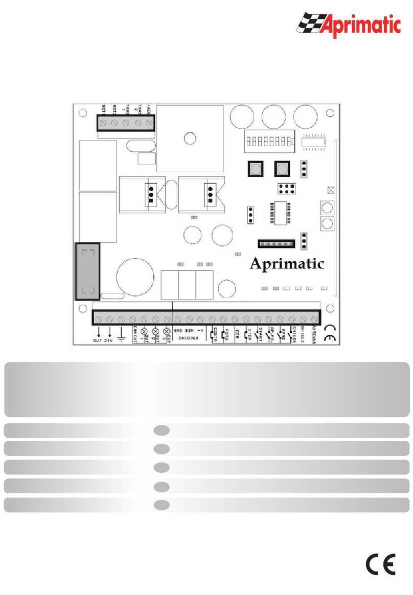
Aprimatic SC 230 Quick start guide

SC 230
Apparecchiatura di controllo per automazione cancelli scorrevoli a 230 V
Unit for the automatic control of sliding gates 230 V
Platine de commande pour l’automatisation de portails coulissants 230 V
Italiano
SCOPO DEL MANUALE
Questo manuale è stato redatto dal costruttore ed è parte integrante del prodotto.
In esso sono contenute tutte le informazioni necessarie per:
• la corretta sensibilizzazione degli installatori alle problematiche della sicurezza;
• la corretta installazione del dispositivo;
• la conoscenza approfondita del suo funzionamento e dei suoi limiti;
• il corretto uso in condizioni di sicurezza;
La costante osservanza delle indicazioni fornite in questo manuale, garantisce la sicurezza dell’uomo, l’economia
di esercizio e una più lunga durata di funzionamento del prodotto.
Al fine di evitare manovre errate con il rischio di incidenti, è importante leggere attentamente questo manuale,
English
rispettando scrupolosamente le informazioni fornite.
Le istruzioni, i disegni, le fotografie e la documentazione contenuti nel presente manuale sono di proprietà
APRIMATIC S.p.a. e non possono essere riprodotti in alcun modo, né integralmente, né parzialmente.
Il logo “APRIMATIC” è un marchio registrato di APRIMATIC S.p.a.
PURPOSE OF THE MANUAL
This manual was drawn up by the manufacturer and is an integral part of the product.
It contains all the necessary information:
• to draw the attention of the installers to safety related problems
• to install the device properly
• to understand how it works and its limits
Español
• to use the device under safe conditions
Strict observance of the instructions in this manual guarantees safe conditions as well as ef fi cient operation and
a long life for the product.
To prevent operations that may result in accidents, read this manual and strictly obey the
instructions provided.
Instructions, drawings, photos and literature contained herein are the exclusive property of the
manufacturer and may not be reproduced by any means.
The “Aprimatic” logo is a trademark registered by Aprimatic S.p.A.
BUT DU MANUEL
Ce manuel a été rédigé par le constructeur et fait partie intégrante du produit.
Il contient toutes les informations nécessaires pour :
sensibiliser les installateurs aux problèmes liés à la sécurité ;
installer le dispositif de manière correcte ;
connaître le fonctionnement et les limites du dispositif ;
utiliser correctement le dispositif dans des conditions de sécurité optimales ;
Le respect des indications fournies dans ce manuel garantit la sécurité personnelle, une économie de fonctionnement
et une longue durée de vie du produit.
Afi n d’éviter des opérations incorrectes et de ne pas risquer des accidents sérieux, lire attentivement ce manuel et
respecter scrupuleusement les informations fournies.
Les instructions, les dessins, les photos et la documentation contenus dans ce manuel sont la propriété d’APRIMATIC
S.p.A. et ne peuvent être reproduits sous aucune forme, ni intégralement, ni partiellement.
Le logo « Aprimatic » est une marque déposée par Aprimatic S.p.A.
ZWECK DES HANDBUCHS
Dieses Handbuch wurde vom Hersteller verfasst und ist ein ergänzender Bestandteil des Produkts.
Es enthält alle nötigen Informationen für:
• die Sensibilisierung der Monteure für Fragen der Sicherheit;
• die vorschriftsmäßige Installation der Vorrichtung;
• die umfassende Kenntnis ihrer Funktionsweise und ihrer Grenzen;
• die vorschriftsmäßige und sichere Benutzung.
Die Beachtung der in diesem Handbuch enthaltenen Anweisungen gewährleistet die Sicherheit der Personen, den
wirtschaftlichen Betrieb und eine lange Lebensdauer des Produkts.
Zur Vermeidung von Fehlbedienung und somit Unfallgefahr dieses Handbuch aufmerksam durchlesen und die
Anweisungen genau befolgen.
Die Anleitungen, Zeichnungen, Fotos und Dokumentationen in diesem Handbuch sind Eigentum von APRIMATIC
S.p.A. und dürfen in keiner Weise ganz oder teilweise reproduziert werden.
Das Logo „Aprimatic“ ist ein eingetragenes Warenzeichen der Aprimatic S. p. A.
OBJETO DEL MANUAL
Este manual ha sido redactado por el constructor y forma parte integrante del producto.
El mismo contiene todas las informaciones necesarias para:
• la correcta sensibilización de los instaladores hacia los problemas de la seguridad
• la correcta instalación del dispositivo
• el conocimiento en profundidad de su funcionamiento y de sus límites
• el correcto uso en condiciones de seguridad
La constante observación de las indicaciones suministradas en este manual, garantiza la seguridad del hombre,
la economía del ejercicio y una mayor duración de funcionamiento del producto.
Con el fi n de evitar maniobras equivocadas con riesgo de accidente, es importante leer atentamente este manual,
Istruzioni di installazione elettrica Uso e
Manutenzione
E
lectrical installation, Use and Maintenanc
e
Instructions
Instructions d’installation éléctrique,
d'Utilisation et d’Entretien
Anleitun
g
f
ür die elektrische Installation,
Gebrauch und Wartun
g
Instrucciones para la instalación electrica,
el uso
y
el mantenimiento
respetando escrupulosamente las informaciones suministradas.
Las instrucciones, los dibujos, las fotografías y la documentación que contiene este manual son propiedad de
APRIMATIC S.p.a. y no pueden ser reproducidas en ninguna manera, ni integral ni parcialmente.
El logotipo “Aprimatic” es una marca registrada de Aprimatic S. p. A.
LBT0344 – DS41626-001A
SC 230
PREMESSA AL MANUALE ISTRUZIONI
Le presenti istruzioni riguardano esclusivamente l’installazione elettrica e l’utilizzo del sistema di controllo con
apparecchiatura SC230.
La predisposizione dei collegamenti elettrici di tutti i dispositivi del proprio sistema deve essere effettuata prima di iniziare
l’installazione dei componenti, attenendosi allo schema di “Predisposizione dell'impianto elettrico" fornito nel manuale
istruzioni dell'attuatore, alle avvertenze fornite in questo manuale e alle istruzioni allegate ai componenti installati.
Nel corso delle operazioni di assemblaggio e montaggio e collaudo dell’automatismo si possono verificare situazioni di
pericolo se non si osservano le avvertenze di sicurezza contenute nelle istruzioni. Prima di procedere leggere attentamente il
presente manuale istruzioni. Rendere disponibili le istruzioni presso l’impianto per ogni necessità di utilizzo e manutenzione.
Le istruzioni dei prodotti Aprimatic sono reperibili sul sito www.aprimatic.it
I dati riportati sono da ritenersi puramente indicativi. Il costruttore declina ogni responsabilità per le possibili inesattezze
contenute nel presente manuale derivanti da errori di stampa o di trascrizione.
L’azienda si riserva il diritto di apportare modifiche atte a migliorare il prodotto senza preavviso.
AVVERTENZE GENERALI E DI SICUREZZA
Leggere attentamente le istruzioni prima di iniziare l’installazione del prodotto.
I materiali dell’imballaggio (plastica, polistirolo, ecc.) non vanno dispersi nell’ambiente e non devono
essere lasciati alla portata dei bambini in quanto potenziali fonti di pericolo. La non corretta installazione dell’apparecchiatura
può provocare gravi pericoli, seguire attentamente tutte le istruzioni per l’installazione. Si raccomanda di lavorare nel pieno
rispetto delle norme di sicurezza; di operare in ambiente sufficientemente illuminato e idoneo per la salute; di indossare
indumenti di protezione a norma di legge (scarpe antinfortunistiche, occhiali di protezione, guanti ed elmetto) evitando di
indossare articoli di abbigliamento che possano impigliarsi. adottare misure di protezione adeguate al rischio di ferita dovuto a
schegge acuminate e ai possibili rischi di schiacciamento, urto e cesoiamento. Si raccomanda di osservare rigorosamente le
norme nazionali valide per la sicurezza nei cantieri. Delimitare il cantiere per impedire il transito a persone non autorizzate e
non lasciare incustodita la zona di lavoro. Installazione, collegamenti elettrici e regolazioni devono essere effettuati
nell’osservanza della buona tecnica e in ottemperanza alle norme vigenti nel paese di installazione. Il costruttore della
motorizzazione non è responsabile dell’inosservanza della buona tecnica nella costruzione della struttura da motorizzare, né
delle deformazioni che dovessero intervenire nell’utilizzo.
Un’errata installazione può essere fonte di pericolo. Eseguire gli interventi come specificato dal costruttore.
Prima di iniziare l’installazione, verificare l’integrità del prodotto e verificare che la struttura esistente abbia i necessari requisiti
di robustezza e stabilità e che risponda alle normative di settore vigenti. L’installazione, il collaudo e la messa in funzione
della chiusura pedonale, così come le verifiche periodiche e gli interventi di manutenzione, possono essere eseguiti soltanto
da tecnici specializzati e formati sul prodotto.
L’intero impianto deve essere realizzato da personale qualificato e in perfetta conformità con le norme vigenti nel Paese di
installazione (norme CEI 64 - 8 / EN 60335-1).
E’ necessario seguire un corso di specializzazione. A questo scopo gli installatori sono invitati a contattare il fornitore.
L’apparecchiatura SC230 è stata progettata per controllare il funzionamento di motori
elettromeccanici a 230V per l'automazione di cancelli scorrevoli.
È vietato utilizzare il prodotto per scopi diversi da quelli previsti o impropri. Si raccomanda di attenersi altresì ai
limiti di impiego indicati nel manuale di installazione dell'attuatore. È vietato manomettere o modificare il prodotto. Il
prodotto deve essere istallato solo con materiale APRIMATIC.
Aprimatic srl non assume responsabilità per il mancato rispetto di tali prescrizioni.
L’apparecchio può essere utilizzato da bambini di età non inferiore a 8 anni e da persone con ridotte capacità fisiche,
sensoriali o mentali, o prive di esperienza o della necessaria conoscenza, purché sotto sorveglianza oppure dopo che le
stesse abbiano ricevuto istruzioni relative all’uso sicuro dell’apparecchio e alla comprensione dei pericoli ad esso inerenti.
I bambini devono essere sorvegliati affinchè non giochino con l’apparecchio, incluso il telecomando. La pulizia e la
manutenzione destinata ad essere effettuata dall’utilizzatore non deve essere effettuata da bambini senza sorveglianza.
2

SC 230
L’impianto di alimentazione elettrica deve essere eseguito da un elettricista esperto e abilitato secondo
i criteri nazionali, nel rispetto delle norme nazionali di sicurezza degli impianti.
Prima di collegare l’alimentazione elettrica accertarsi che i dati di targa siano rispondenti a quelli della rete di distribuzione
elettrica. Le misure di protezione sul primario vengono adottate in cantiere / in opera.
Come interruttore generale della tensione di rete utilizzare un interruttore differenziale magnetotermico di 6A a intervento
30mA, categoria III.
Prima di procedere a qualsiasi intervento di manutenzione, riparazione o sostituzione sia meccaniche che elettriche è
necessario interrompere l’alimentazione elettrica di rete.
Il collaudo e la messa in funzione dell’automazione non sono consentiti fino a quando non sia stato verificato che il cancello
automatico scorrevole è conforme alla quale il cancello completo, montato e installato è assoggettato.
L’installatore deve verificare che il range di temperatura indicato in etichetta sia compatibile con il luogo di installazione.
L’installatore è tenuto a produrre e conservare il fascicolo tecnico del cancello automatico e deve ottemperare a tutti gli
adempimenti previsti. al termine del lavoro l’installatore deve verificare l’installazione e il corretto funzionamento
dell’automazione.
Deve eseguire l’analisi dei rischi e verificare che l’impianto non presenti punti di schiacciamento o cesoiamento. Se
necessario deve adottare adeguate misure correttive e applicare le segnalazioni previste dalle norme vigenti per individuare le
zone pericolose.
Ogni installazione deve riportare in modo visibile l’indicazione dei dati identificativi del sistema motorizzato.
L’installatore deve fornire tutte le informazioni relative al funzionamento automatico, manuale e di emergenza del cancello
motorizzato e consegnare le istruzioni d’uso all’utilizzatore dell’impianto. per eventuali riparazioni o sostituzioni dovranno
essere utilizzati esclusivamente ricambi originali.
Non si riconosce la garanzia in caso di utilizzo combinato con componenti di altra marca.
Il costruttore della motorizzazione declina ogni responsabilità qualora vengano installati componenti incompatibili ai fini della
sicurezza e del buon funzionamento.
Impianto tipo
• L’intero impianto deve essere realizzato in perfetta conformità con le norme CEI 61 - 1 e CEI 64 – 8
• L’installatore deve verificare che il range di temperatura indicato in etichetta sia compatibile con il luogo di
installazione.
• Gli accessori indicati in figura non sono forniti con l’apparecchiatura.
• Utilizzare per gli allacciamenti cavo elettrico sezione 1,5 mm2 FROR CEI 20-22.
• Per il fissaggio del box plastico dell’apparechiatura utilizzare i fori prestampati nel box, fissare con tasselli adatti
al supporto che si è scelto e sigillare con silicone.
• Se si rendesse necessario inserire una guaina di protezione nel cavo di alimentazione dell’attuatore, eseguire
l’operazione prima .
di effettuare l’allacciamento del cavo stesso alle scatole di derivazione.
• Se il cavo di alimentazione dovesse essere danneggiato, esso deve essere sostituito dal servizio di assistenza
tecnica qualificato.
3

SC 230
LAYOUT Funzioni SC230 e caratteristiche tecniche
TRIMMER
DSW1 DESCRIZIONE OFF ON
1 RICHIUSURA AUTOMATICA DISABILITATA(1) ABILITATA(2)
2 FUNZIONAMENTO SEQ E PED DISABILITATA ABILITATA
3 FUMZIONE CORTESIA (3) DISABILITATA ABILITATA
4 FUNZIONAMENTO
CONDOMINIALE (4)
DISABILITATA ABILITATA
5 SOFT START DISABILITATA ABILITATA
6 PRELAMPEGGIO DISABILITATA ABILITATA
7 VERSO DI APERTURA SINISTRA DESTRA
8 TIPO INGRESSO SAF DIGITALE RESISTIVO
9 FUNZIONE USCITA +TST LAMPEGGIANTE TEST SICUREZZA
10 LIBERO
TR1 DELAY Regola il tempo di
sosta da 1 a 120
secondi.
TR2 TORQ Regola la coppia del
motore
TR3 SL Regola la velocità in
fase di rallentamento.
(5)
TR4 BRK Regola l’intensità del
freno a fine
movimento
TR5 SENSE Regola la sensibilità
antischiacciamento
1) Apertura – Stop – Chiusura – Stop – Eccetera.
2) Apertura – Chiusura – Apertura – Eccetera
3) La Funzione cortesia abilita la chiusura dopo 5 secondi che le fotocellule hanno ricevuto un impulso indipendentemente dal
tempo di lavoro.
4) La funzione condominiale disabilita i comandi SEQ e PED durante l’apertura.
5) Regolando il trimmer al massimo (completa rotazione in senso orario) viene escluso il rallentamento.
6) Disimpegna si intende breve inversione del moto e relativo STOP del movimento.
Tabella 1- Dati tecnici
TENSIONE DI ALIMENTAZIONE MONOFASE 230V AC +6% -10%
FREQUENZA 50 Hz
ALIMENTAZIONE MOTORE 230V AC +6% -10%
TENSIONE PER DISPOSITIVI ESTERNI 24 V DC +15% -10%
CORRENTE MAX DISPOSITIVI ESTERNI 350 mA
CONSUMO APPARECCHIATURA (con accessori, senza motori) 12 W
POTENZA EROGATA (pilotaggio motori) 650W
PROTEZIONE APPARECCHIATURA E ACCESSORI Fusibile ritardato F630mA (F1)
PROTEZIONE MOTORE Fusibile da F5A (F2)
CAMPO DI TEMPERATURE -20° ↔+70° C interno cassonetto
GRADO DI PROTEZIONE Dipende dal contenitore
DIMENSIONI (LxHxP) mm 107 x 100 x 50 (misure indicative)
4

SC 230
COLLEGAMENTI
Descrizione
19 24
18 -24 Alimentazione Accessori 24 V DC
17 OPEN Comanda l’apertura se il cancello è fermo.
Se il cancello è in chiusura, inverte il movimento.
16 PED/C
L
Comanda l’apertura pedonale se il cancello è chiuso.
Comanda la chiusura se il cancello è aperto o fermo.
15 SEQ Comanda l’apertura se il cancello è chiuso.
Comanda la chiusura se il cancello è fermo.
14 STOP Comanda l’arresto di ogni movimento e finché è attivo impedisce ogni movimento.
13 PH1 Input Fotocellula 1: se in chiusura, inverte il movimento e finché è impegnata impedisce la
chiusura.
12 PH2 Input Fotocellula 2: provoca l’arresto di ogni movimento. Finché è impegnata impedisce
ogni movimento. Al disimpegno: apertura.
11 SAF Ingresso per costa di sicurezza.
10 COM Comune inputs
9 +AUX Spia remota dello stato dell’automazione:
• lampeggio veloce in chiusura;
• lampeggio lento in apertura;
• luce fissa : battenti NON chiusi;
• luce spenta : battenti chiusi
M1
8 +TST Se dip 9 ON: Out Test sicurezze
Se dip 9 OFF: Out Lampeggiante a LED
7 MCL Avvolgimento Chiusura Motore
6 MOP Avvolgimento Apertura Motore
5 MCOM Comune Motore
4 L Linea 230 V AC
M2
3 N Neutro 230 V AC
2 PE Terra 230 V AC
M3 1 PE Terra 230 V AC
20 GND Massa Antenna Radio
M4 21 ANT Polo Antenna Radio
25 CLL Finecorsa cancello chiuso
24 OPL Finecorsa cancello aperto
23 -24 Comune inputs
M5
22 24 Alimentazione Accessori +24 V DC
CN1 Connettore encoder
CN2 Connettore modulo aggiuntivo per uscita 2° canale
K3 Connettore a tre pin per innesto accessori; collegamento scheda radio ricevente UNICO (alternativa
alla ricevente integrata) – Decoder controllo accessi.
Sequenze logiche di funzionamento
Configurazione Dip Switch DSW1
DIP1 DIP2 LOGICA NOTE
ON OFF AUTOMATICA Utilizzare ingresso OPEN (Morsetto 17)
OFF ON PASSO – PASSO Utilizzare ingresso SEQ (Morsetto 15)
ON ON AUTOMATICA SUPER Utilizzare ingresso SEQ (Morsetto 15)
ON OFF AUTOMATICA CON STOP Utilizzare ingresso SEQ (Morsetto 15)
OFF OFF PASSO – PASSO CON STOP Utilizzare ingresso SEQ (Morsetto 15)
5

SC 230
AUTOMATICO: Selezionando questo tipo di funzionamento, quando viene inviato un impulso OPEN (morsetto 17) , si
comanda l’apertura fino allo scadere del tempo di lavoro, il cancello rimane aperto per il tempo di pausa selezionato(TR1
DELAY) e quindi si chiude automaticamente.
Nel caso in cui venga inviato un impulso OPEN durante la fase di apertura, il sistema di controllo lo ignora e il cancello
prosegue il movimento di apertura.
Se viene inviato un impulso OPEN o se vengono impegnate le fotocellule durante la fase di chiusura, si inverte la direzione di
movimento (cioè il cancello apre).
Se il contatto OPEN viene mantenuto chiuso, il cancello apre e resta bloccato aperto ignorando il tempo di pausa impostato.
PASSO – PASSO:Selezionando questo tipo di funzionamento, quando viene inviato un impulso SEQ (morsetto 15), si
comanda l’apertura fino allo scadere del tempo di lavoro, il cancello rimane aperto senza il tempo di pausa.
Per chiudere il cancello dare un impulso SEQ.
Nella fase di chiusura il cancello, un impulso SEQ apre e si blocca aperto.
Nella fase di apertura il cancello inverte e va in chiusura.
AUTOMATICA SUPER:Selezionando questo tipo di funzionamento, quando viene inviato un impulso SEQ (morsetto 15), si
comanda l’apertura fino allo scadere del tempo di lavoro, il cancello rimane aperto per il tempo di pausa selezionato(TR1
DELAY) e quindi si chiude automaticamente.
Durante il tempo di pausa impostato (TR1 DELAY) un ulteriore SEQ comanda la chiusura del cancello
Nella fase di chiusura dando un comando SEQ il cancello riapre
Nella fase di apertura dando un comando SEQ il cancello si richiude
AUTOMATICA CON STOP: Stesso comportamento della logica AUTOMATICA SUPER, con la differenza che:
Nella fase di chiusura dando un comando SEQ il cancello si blocca , un ulteriore comando APRE
Nella fase di apertura dando un comando SEQ il cancello si blocca, tempo pausa impostato e CHIUDE
PASSO – PASSO CON STOP: Stesso comportamento della logica PASSO - PASSO , con la differenza che:
Nella fase di apertura dando un comando SEQ il cancella si blocca, dando un altro impulso si comanda la chiusura.
Nella fase di chiusura dando un comando SEQ il cancello si blocca, dando un altro impulso si comanda l’apertura.
Quindi il Dip Switch 1 attiva il tempo di pausa TR1 DELAY e Dip Switch 2 attiva la funzione di fermata o inversione del moto
delle ante.
TEST SICUREZZE
E' possibile collegare dispositivi di sicurezza sorvegliati agli ingressi PH1, PH2 e SAF.
Nel caso di fotocellule tradizionali alimentarne il trasmettitore attraverso l'uscita +TST.
Nel caso di fotocellule o altri dispositivi dotati di input di test, collegare tale input all'uscita +TST.
Se viene collegato almeno un dispositivo sorvegliato, è necessario posizionare il dip 9 su ON: l'apparecchiatura effettuerà il
test dei dispositivi sorvegliati:
Input sorvegliato Esecuzione del test Reazione
PH1 All'inizio della manovra di chiusura Apre
PH2 All'inizio delle manovre di chiusura e apertura Apre
SAF All'inizio delle manovre di chiusura e apertura Nella fase di chiusura , disimpegna (6) ed
attende un comando SEQ apre, nella fase di
apertura disimpegna tempo pausa chiude.(
esempio con logica gestita col tempo pausa).
Durante l'apprendimento delle corse vengono automaticamente riconosciuti i dispositivi di sicurezza sorvegliati.
Se nessun dispositivo sorvegliato viene riconosciuto e il dip 9 è in ON, i successivi test delle sicurezze falliranno e non
verranno eseguiti movimenti del cancello!
APPRENDIMENTO TELECOMANDI
L'apparecchiatura SC230 è dotata di un decodificatore incorporato capace di memorizzare fino a 250 telecomandi.
1.1 Funzione SEQ
Premere il pulsante P2 fino a quando il led PROG comincia a lampeggiare. Rilasciare P2.
Entro 10 secondi attivare il tasto del telecomando che si desidera sia associato al comando di SEQ. L'avvenuto
apprendimento sarà segnalato da un lampeggio lungo del led PROG.
Ripetere l'operazione per ogni telecomando da apprendere.
6

SC 230
1.2 Funzione PED (o CH2)
Premere il pulsante P2 fino a quando il led PROG comincia a lampeggiare; non rilasciare P2 e attendere che il lampeggio
diventi più veloce. Rilasciare il pulsante P2
Entro 10 secondi attivare il tasto del telecomando da apprendere che si desidera sia associato al comando PED. L'avvenuto
apprendimento sarà segnalato da un lampeggio lungo del led PROG.
Ripetere l'operazione per ogni telecomando da apprendere.
1.3 Cancellazione di un singolo telecomando appreso
Premere il pulsante P2 fino a quando il led PROG comincia a lampeggiare; non rilasciare P2 e attendere che il lampeggio
diventi più veloce; non rilasciare P2 e attendere che il lampeggio diventi velocissimo; Rilasciare il pulsante P2.
Entro 10 secondi attivare il tasto del telecomando da cancellare. L'avvenuta cancellazione sarà segnalata da un lampeggio
lungo del led PROG.
Ripetere l'operazione per ogni telecomando da cancellare.
1.4 Cancellazione totale dei telecomandi appresi
Accendere l'apparecchiatura tenendo premuto il pulsante P2 fino a quando il led PROG comincia a lampeggiare; non
rilasciare il pulsante e attendere che il lampeggio termini. L'avvenuta cancellazione di TUTTI i telecomandi appresi sarà
segnalata da un lampeggio lungo del led PROG.
1.5 Funzione Modulo Canale MCH2
Per abilitare il comando dell’MCH2 col secondo canale del radiocomando:
premere il pulsante P2 fino a quando il led PROG comincia a lampeggiare; non rilasciare P2 e
attendere che il lampeggio diventi più veloce; non rilasciare P2 e attendere che il lampeggio
diventi ancora più veloce; Rilasciare il pulsante P2.
Proseguire con il punto 1.2 per apprendere il secondo canale di un TM4 associato all’MCH2
1.6 SCHEDA USCITA MCH2
Al connettore CN2 può essere connessa la schedina MCH2.
Tale scheda fornisce due contatti NC e NO che vengono attivati per 1 sec alla ricezione di un
impulso da un pulsante di telecomando associato a MCH2
Se nessun telecomando è stato associato a MCH2 i contatti vengono attivati per 1 sec circa in
seguito ad un comando SEQ, PED o OPEN.
PROGRAMMAZIONE CORSE
Durante la procedura di apprendimento, oltre a memorizzare gli spazi di rallentamento e la corsa di apertura pedonale
l'apparecchiatura rileva l'eventuale presenza di ingressi di sicurezza PH1, PH2 o SAF sorvegliati.
Premere il pulsante di apprendimento P1 per almeno 3 secondi
Il led PROG comincia a lampeggiare: Rilasciare il pulsante P1
Attivare il comando SEQ: Il cancello si muove in chiusura con velocità normale
Il cancello ricerca il finecorsa in posizione chiuso e si arresta.
Dopo 1 sec circa: Il cancello si muove in apertura con velocità normale
Quando si decide di cominciare la fase di corsa rallentata attivare SEQ: il cancello rallenta
Il cancello prosegue fino al finecorsa in posizione aperto e si arresta
Dopo 1 sec circa: Il cancello si muove in chiusura con velocità normale
Quando si decide di cominciare la fase di corsa rallentata attivare SEQ: il cancello rallenta
Il cancello prosegue fino al finecorsa in posizione chiuso e si arresta.
Dopo 1 sec circa: Il cancello si muove in apertura con velocità normale
Per fissare il punto di apertura parziale pedonale attivare SEQ: il cancello si arresta
Dopo 1 sec circa: Il cancello si muove in chiusura fino al finecorsa in posizione chiuso e si arresta. Attendere che il led
PROG si spenga.
Nella fase della programmazione delle corse, se il tempo di pausa (DELAY trimmer TR1) è impostato a 0 secondi, il comando
pedonale si imposterà a tempo pausa di 1 secondo , non modificabile del TR2 DELAY, mentre se si effettua l’apprendimento
delle corse con DELAY > di 1 secondo, il trimmer TR1 DELAY modifica anche il tempo di pausa della funzione pedonale.
7

SC 230
NOTE PER IL MANUTENTORE
MANUTENZIONE PROGRAMMATA
Si raccomanda di consultare la Ditta Installatrice dell’automazione e stabilire un piano di manutenzione programmata, come
richiesto dalle normative di settore.
La manutenzione consigliata da Aprimatic per l’impianto elettrico è la seguente:
Operazione Periodicità media
Verifica del buon funzionamento dei dispositivi di rilevamento e antischiacciamento
(fotocellule, detector, sicurezza (coste) e delle regolazioni 6 mesi
Controllo del buon funzionamento dell’impianto elettrico e test di intervento per dispersione
dell’interruttore automatico differenziale posto a protezione dell’impianto 6 mesi
Controllare l’interno del box elettrico, che deve essere mantenuto pulito e preservato da
insetti o umidità 6 mesi
Verificare l’efficienza delle batterie dei telecomandi - eventualmente sostituirle 6 mesi
Eliminare eventuali ostacoli interposti che oscurino permanentemente il raggio delle
fotocellule (es: rami o cespugli) 6 mesi
Prima di eseguire la manutenzione scollegare l’automazione dalla rete di alimentazione mediante l’interruttore differenziale
dell’impianto elettrico!
Si ricorda che le batterie, in quanto materiale di consumo, non sono coperte da garanzia.
Si raccomanda di non disperdere la batteria nell’ambiente, ma di utilizzare gli appositi contenitori previsti presso i punti
vendita delle batterie stesse.
AVVERTENZE PER L'UTILIZZATORE
Tutte le istruzioni fornite sono parte integrante ed essenziale del prodotto e devono obbligatoriamente essere conservate per
futuri riferimenti fino alla demolizione dello stesso. Esse devono essere consegnate all’utilizzatore e devono essere lette
attentamente poiché contengono importanti avvertimenti per l’uso e la manutenzione.
Questa apparecchiatura deve essere utilizzata esclusivamente per l’uso cui è destinata. Ogni altro utilizzo è improprio e
quindi pericoloso.
È vietato manomettere o modificare il prodotto.
Far eseguire periodicamente una corretta manutenzione, in base al libretto di manutenzione rilasciato dall’installatore.
Il collegamento, il collaudo e la messa in funzione, così come le verifiche periodiche e gli interventi di manutenzione, inclusa
la pulizia dell’azionamento, possono essere eseguiti soltanto da tecnici specializzati e formati sul prodotto.
All'utilizzatore non è consentito intervenire sull'impianto e sull'apparecchiatura di controllo, né operare all'interno del box
elettrico. In caso di guasto o funzionamento non regolare, togliere alimentazione all'automazione azionando l’interruttore
principale. Non tentare di intervenire o di riparare l’unità principale e contattare chi ha installato l'automazione o un altro
installatore specializzato. Non rispettare questo avvertimento può portare a situazioni di pericolo. In caso di guasti o di
mancanza di energia elettrica si può MANOVRARE L'ANTA MANUALMENTE (vedi manuale di installazione dell'attuatore).
Tenere sotto controllo i radiocomandi o altri dispositivi di attivazione del movimento in modo da evitare azionamenti involontari
da parte di bambini o estranei.
Aprimatic s.r.l. dichiara che la scheda SC230 è conforme ai requisiti essenziali ed alle altre disposizioni pertinenti
stabilite dalla direttiva 1995/5/CE.
Aprimatic srl
Via Emilia, 147
40064 Ozzano Emilia (BO)
Tel. +39 051 6960711 – Fax +39 051 6960722
8

SC 230
ABOUT THIS MANUAL
These instructions concern only the electrical installation and the use of the control system with the
equipment SC230. For mechanical installation please see the operator's instructions supplied.
During assembly, installation and test operations of the automatic device, hazardous situations might arise if the safety
warnings contained in the instructions are not followed. Carefully read this instruction manual before proceeding. Instructions
must be available with the system for any use or maintenance operation needed.
The data indicated are to be considered for indicative purposes only. The manufacturer is not to be held responsible for any
inaccuracy contained in this manual arising from printing or transcription mistakes.
The company reserves the right to make changes to improve the product without giving prior notice.
GENERAL SAFETY PRECAUTIONS
Carefully read the instructions before starting to install the product.
Packaging materials (plastic, polystyrene, etc.) must not be dispersed in the environment and must
not be left where children can reach them as they are a potential source of danger. Wrong installation of the equipment can
cause serious danger. Please, follow all installation instructions carefully. We recommend operating in a well-lit and healthy
environment, in compliance with the safety regulations in force. We recommend the use of approved protective clothing
(safety shoes, protective goggles, gloves and helmet). Do not wear articles of clothing that could get caught. Take adequate
safety measures to prevent the risk of injury caused by sharp splinters and the possible risks of crushing, knocks and cuts and
amputation collision and shearing danger. We recommend strict observation of the national regulations for safety in work
sites. Delimit the yard to prevent any unauthorised persons from transiting in the working area. Do not leave the working area
unattended. Installation, electrical connections and adjustments must be carried out in a professional manner in compliance
with the good manufacturing and workmanship regulations in force in the country where the automation is installed. The
manufacturer of the device is not responsible for the non-observance of professional standards of work in the construction of
the power-driven structure, nor for any damage which may be caused by the use of the drive.
Incorrect installation may be dangerous. Follow the manufacturer's instructions.
Before starting installation, check that the product is intact and that the existing structure is suitably strong and stable and that
it is complying with the sector current regulations. Only suitably skilled technicians trained on the product are authorised to
connect up, test and put into service this product.
We strongly recommend following a specialised training course. Installers should contact the supplier for information on
courses.
The equipment SC230 is designed to control functioning of electromeccanical 230-volt to automate
sliding gates operator.
Only use the product for the permitted uses specified. Do not use the product for purposes other than those
specified. You should note the operating restrictions specified in the installation manual supplied with the operator.
Do not tamper with or modify the product. The product must only be installed using APRIMATIC material.
Aprimatic srl declines all liability for damages caused by failure to follow these instructions.
The device can be used by children aged under 8 years and persons with reduced physical, sensory or mental capabilities, or
lack of experience or the necessary knowledge, provided under surveillance or after their having received instructions to
'ensure safe operation and to the understanding of the dangers inherent in it. Children should be supervised to ensure that
they do not play with the device, including the remote control. Cleaning and maintenance meant to be performed by the
user does not have to be made by children without supervision.
9

SC 230
The power supply system must be carried out by a qualified and expert electrician according to the
local requirements, in compliance with local system safety regulations.
Before connecting the power supply make sure that the plate data correspond to those of the electric power distribution grid.
The protection measures on the primary are used on site / in operation.
As main switch of the power supply, use a magnetothermal differential switch of 6A tripping at 30mA cathegory III.
Disconnect the power supply before carrying out any other maintenance operation, repair or replacement, both mechanical
and electrical.
Test and commissioning of the automatic device are not allowed until the sliding automatic gate has not been verified as
complying with the requirements that the finished, assembled and installed gate is subject to.
The installer must check that the temperature range indicated on the label is compatible with the installation site
The installer must keep and store the technical documentation of the automatic gate and must fulfil all obligations required. At
the end of the job the installer must check the installation and the correct operation of the automatic device.
The installer must carry out a risk analysis and check that the system does not feature crushing or shearing points. If
necessary, corrective measures must be implemented and signals required by current regulations must be applied in order to
make the dangerous areas visible.
The identification data of the motorised system must be clearly visible on each installation.
The installer must provide full information about the automatic, manual and emergency functioning of the equipment and
deliver the operating instructions to the system user. Only use original spare parts for any repairs or for replacing parts.
The guarantee is void if this product is used in combination with others of other brands.
The manufacturer of the drive declines any responsibility if components incompatible with safety and correct operation are
installed.
Typical setup
• The entire circuit must be installed in conformity with the CEI 61-1 and CEI 64-8 regulations.
• The accessories in the picture are not provided with the control board.
• Use cable of cross-section 1.5 mm 2 FROR CEI 20-22 for the wiring.
• To fasten the control board plastic box use the pre printed holes in the box , fix with suitable plugs for the support
that you chose and seal with silicone.
• If necessary, protect the operator power cable with a sheath; do this before connecting the cable to the junction
box.
• If the power supply cable is damaged, it must be replaced by qualified technical service.
10

SC 230
LAYOUT of SC230 functions and technical specifications
TRIMMER
DSW1 DESCRIPTION OFF ON
1 AUTOMATIC RECLOSING DISABLED (1) ENABLED (2)
2 SEQ AND PED OPERATION DISABLED ENABLED
3 COURTESY FUNCTION (3) DISABLED ENABLED
4 CONDOMINIUM OPERATION (4) DISABLED ENABLED
5 SOFT START DISABLED ENABLED
6 PRE-FLASHING DISABLED ENABLED
7 OPENING DIRECTION LEFT RIGHT
8 SAF INPUT TYPE DIGITAL RESISTIVE
9 OUTPUT FUNCTION + TST FLASHING LIGHT SAFETY DEVICE TEST
10 SPARE
TR1 DELAY It adjusts stop time from
1 to 120 seconds.
TR2 TORQ It adjusts the torque of
the motor
TR3 SL It adjusts the speed
during slowing down
phase. (5)
TR4 BRK It adjusts brake power at
the end of the movement
TR5 SENSE It adjusts anti-crush
sensitivity
1) Opening – Stop – Closing – Stop – Etc.
2) Opening – Closing – Opening – Etc.
3) The Courtesy function enables the closing 5 seconds after the photocells have received a pulse, regardless of the working time.
4) The condominium function disables the SEQ and PED controls during opening.
5) Slowing down is completely disabled if the trimmer is fully turned (full clockwise rotation).
6) Disable means that it slightly reverses the drive and STOPS the movement.
Table 1- Technical data
SINGLE-PHASE POWER SUPPLY VOLTAGE 230V AC +6% -10%
FREQUENCY 50 Hz
MOTOR POWER SUPPLY 230V AC +6% -10%
EXTERNAL DEVICES VOLTAGE 24 V DC +15% -10%
EXTERNAL DEVICES MAXIMUM CURRENT 350 mA
MAXIMUM ABSORBED POWER (with accessories connected and
functioning,excluding motors)
12 W
ABSORBED POWER (driving motors) 650W
ACCESSORIES AND EQUIPMENT PROTECTION Delayed fuse F630mA (F1)
MOTOR PROTECTION F5A (F2) fuse
TEMPERATURE RANGE -20° ↔+70° C inside container
PROTECTION CLASS According to container
DIMENSIONS (LxHxD) mm 107 x 100 x 50 (indicative measures)
11

SC 230
CONNECTIONS
Description
19 24
18 -24
Accessory power supply 24 V DC
17 OPEN It controls the opening if the gate is stopped.
If the gate is closing, it inverts the movement.
16 PED/C
L
It controls the pedestrian opening if the gate is closed.
It controls the closing if the gate is opened or stopped.
15 SEQ It controls the opening if the gate is closed.
It controls the closing if the gate is stopped.
14 STOP It controls the stopping of every movement and, if enabled, it prevents any movement.
13 PH1 Photocell 1 input: during closing, it inverts the movement and, if enabled, it prevents
closing.
12 PH2 Photocell 2 input: it stops any movement. If enabled it prevents any movement. When
disabled: opening.
11 SAF Input for safety edge.
10 COM Common inputs
9 +AUX Remote warning light of automation status:
• flashing fast during closing;
• flashing slow during opening;
• fixed light: swing gates NOT closed;
• light off: swing gates closed
M1
8 +TST If dip 9 ON: Safety devices Test Out
If dip 9 OFF: LED flashing light Out
7 MCL Motor Closing Winding
6 MOP Motor Opening Winding
5 MCOM Motor Common
4 L Line 230 V AC
M2
3 N Neutral 230 V AC
2 PE Earth 230 V AC
M3 1 PE Earth 230 V AC
20 GND Radio Antenna Ground Connection
M4 21 ANT Radio Antenna Pole
25 CLL Closed gate limit switch
24 OPL Open gate limit switch
23 -24 Common inputs
M5
22 24 Accessory power supply +24 V DC
CN1 Encoder connector
CN2 Additional module connector for second channel output
K3 Three-pin connector for accessories insertion; UNICO receiving radio board connection (alternative to
the integrated receiving unit) - Access control decoder.
Operating logic sequences
Dip Switch DSW1 Configuration
DIP1 DIP2 LOGIC NOTES
ON OFF AUTOMATIC Use OPEN input (Terminal 17)
OFF ON STEP - STEP Use SEQ input (Terminal 15)
ON ON SUPER AUTOMATIC Use SEQ input (Terminal 15)
ON OFF AUTOMATIC WITH STOP Use SEQ input (Terminal 15)
OFF OFF STEP - STEP WITH STOP Use SEQ input (Terminal 15)
12

SC 230
AUTOMATIC: When an OPEN (terminal 17) pulse is sent and this type of operation is selected, the opening will be controlled
until the working time is elapsed, the gate will stay open for the set stop time (TR1 DELAY) and then will close automatically.
- If an OPEN pulse is sent during opening, the control system will ignore it and the gate will carry on opening.
- If an OPEN pulse is sent or if the photocells are engaged during closing, the movement direction will be inverted (gate
will open).
- If the OPEN contact is kept closed, the gate opens and stays open ignoring the stop time set.
STEP - STEP:When a SEQ (terminal 15) pulse is sent and this type of operation is selected, the opening will be controlled
until the working time is elapsed, the gate will stay open with no set stop time.
- To close the gate send a SEQ pulse.
- During gate closing, one SEQ pulse will open the gate that will stay open.
- During opening the gate will invert direction and close.
SUPER AUTOMATIC:When a SEQ (terminal 15) pulse is sent and this type of operation is selected, the opening will be
controlled until the working time is elapsed, the gate will stay open for the set stop time (TR1 DELAY) and then will close
automatically.
- During set stop time (TR1 DELAY) another SEQ pulse will make the gate close
- During closing, if a SEQ pulse is sent the gate will open again
- During opening, if a SEQ pulse is sent the gate will close again
AUTOMATIC WITH STOP: It works with the same logic of the SUPER AUTOMATIC, but with the following differences:
- During closing, if a SEQ pulse is sent the gate will stop, a further pulse will OPEN it
- During opening, if a SEQ pulse is sent, the gate will stop, a stop time set and CLOSES
STEP - STEP WITH STOP: It works with the same logic of the STEP - STEP, but with the following differences:
- During opening, if a SEQ pulse is sent the gate will stop, a further pulse will make the gate close.
- During closing, if a SEQ pulse is sent the gate will stop, a further pulse will make the gate open.
Dip Switch 1 will enable the stop time TR1 DELAY and Dip Switch 2 will enable the stop function or wings movement
inversion.
SAFETY DEVICES TEST
It is possible to connect the supervised safety devices to inputs PH1, PH2 and SAF.
In case of traditional photocells, power their transmitter by means of output +TST.
In case of photocells or other devices equipped with test input, connect this input to output +TST.
If at least one supervised device is connected, it is necessary to set the dip 9 to ON: the equipment will carry out the
test of the supervised devices:
Supervised Input Running the test Reaction
PH1 At the beginning of the closing manoeuvre Opens
PH2
A
t the beginning of the closing and opening
manoeuvres
Opens
SAF
A
t the beginning of the closing and opening
manoeuvres
During the closing phase, it releases (6) and
waits for a SEQ open pulse, in the opening
phase it releases close stop time. (example
with logic managed with stop time).
During stroke memorization the supervised safety devices are automatically recognised.
If no supervised device is recognised and dip 9 is set to ON, the following safety device tests will fail and the gate will not
move!
1) SAVING THE REMOTE CONTROLS
The equipment SC230 is provided with an integrated decoder able to store up to 250 remote controls.
1.1 SEQ Function
Press the P2 button until the PROG LED starts flashing. Release P2.
Enable the remote control key that you want to assign to the SEQ control within 10 seconds. Saving is completed when the
PROG LED will flash for a longer time.
Repeat the operation for each remote control to save.
13

SC 230
1.2 PED Function (or CH2)
Press P2 button until PROG LED starts flashing; do not release P2 and wait for the flashing to become faster. Release P2
button
Enable the remote control key to be saved that you want to assign to the PED control within 10 seconds. Saving is completed
when the PROG LED will flash for a longer time.
Repeat the operation for each remote control to save.
1.3 Deleting a single remote control
Press P2 button until PROG LED starts flashing; do not release P2 and wait for the flashing to become faster; do not release
P2 and wait for the flashing to become very fast. Release P2 button.
Enable the key of the remote control that you want to delete within 10 seconds. Delete operation is completed when the
PROG LED will flash for a longer time.
Repeat the operation for each remote control to delete.
1.4 Deleting all remote controls
Switch-on the equipment by pressing the P2 button until the PROG LED starts flashing; do not release the button and wait for
the flashing to stop. ALL remote controls are deleted when the PROG LED will flash for a longer time.
1.5 Module Channel MCH2 function
To enable dell'MCH2 command with the second radio control channel:
press the P2 button until the PROG LED starts blinking; not release P2 and
wait until the flash gets quicker; not release P2 and wait for the flashing
become even faster; Release the P2 button.
Continue with point 1.2 to learn the second channel of a TM4 associated all'MCH2
1.6 DATA OUTPUT MCH2
CN2 connector can be connected to the coupon MCH2.
This board provides two NC and NO contacts that are activated for 1 sec at the reception of a
pulse from a remote control button associated with MCH2
If no remote control has been associated with MCH2 contacts are activated for about 1 sec in
Following a SEQ command, PED, or OPEN.
2) STROKE PROGRAMMING
During saving, beside saving the slowing down spaces and the pedestrian opening stroke, the equipment will detect any
supervised safety input PH1, PH2 or SAF.
Press the save button P1 for at least 3 seconds
The PROG LED starts flashing: Release P1 button
Enable SEQ pulse: The gate closes at normal speed
The gate searches the limit switch in closed position and stops.
After about 1 sec: The gate opens at normal speed
When you decide to start the slowing down stroke phase, enable SEQ:the gate slows down
The gate reaches the limit switch in open position and stops
After about 1 sec: The gate closes at normal speed
When you decide to start the slowing down stroke phase, enable SEQ:the gate slows down
The gate reaches the limit switch in closed position and stops.
After about 1 sec: The gate opens at normal speed
To fix the partial pedestrian opening, enable SEQ: the gate stops
After about 1 sec: The gate closes until the limit switch in closed position is reached and stops. Wait for the PROG
LED to turn off.
During stroke programming phase, if the stop time (TR1 trimmer DELAY) is set to 0 seconds, the pedestrian control will set to
stop time of 1 second of TR2 DELAY which cannot be changed; while if strokes are learned with DELAY > than 1 second, the
TR1 trimmer DELAY also changes the pedestrian function stop time.
14

SC 230
3 NOTES FOR MAINTENANCE TECHNICIANS
3.1 ROUTINE MAINTENANCE
You should ask the company that installs the automation to provide a scheduled maintenance plan in compliance with the
regulations for this type of equipment.
The maintenance operation suggested by Aprimatic for the electrical system is the following:
Operation Average interval
Check the efficiency and adjustment of safety devices and the anti-crush device. Check the
photocells, the detector and the safety edge every 6 months
Check the efficiency of the electrical equipment. Test the efficiency of the
differential overload switch protecting the unit every 6 months
Check the inside of the electrical box. Clean out any insects, dirt or dampness every 6 months
Check the efficiency of the remote control batteries. Change spent batteries every 6 months
Remove branches, bushes or other obstacles which might permanently obstruct or interrupt
the photocell beam every 6 months
Before you start any maintenance operations, disconnect the automation from the mains power supply using the
system electrical differential switch!
Batteries are consumables and as such are not covered by the guarantee.
Do not throw away old batteries with household waste. Dispose of old batteries using the old battery containers provided at
sales outlets.
1 INFORMATION FOR THE USER
This instruction manual is an integral part of the product and should accompany the product throughout its life cycle up until
decommissioning. It should be stored in a accessible place ready for immediate reference. The instructions and warnings
must be given to the user and then read carefully because they include important warnings for use and maintenance.
Use this equipment for the permitted uses only. All other uses constitute improper and hazardous use.
Do NOT tamper with or modify the product in any way.
Perform maintenance at the recommended intervals. See the maintenance manual and schedule issued by the installer.
Only suitably skilled technicians trained on the product are authorised to connect up, test, put into service, clean
and maintain this product.
The user is not allowed to operate neither on the system or on the control unit, neither within the electrical box. In
the event of any faults, disconnect the operator from the mains power supply using the main switch. Do not attempt
to repair the equipment and contact the installer or other specialist assistance centre. Failure to follow these
instructions may result in hazardous situations. In the event of an operating fault or a mains power failure you can
OPERATE THE GATE BY HAND (for instructions, see the Operator installation manual).
Keep remote control and other control units in a safe place to prevent use by children or unauthorised people.
Aprimatic s.r.l. dieclares that control unit SC230 is in compliance with the essential requirements and other relevant
provisions of Directive 1999/5/EC.
15
Aprimatic srl
Via Emilia, 147
40064 Ozzano Emilia (BO)
Tel. +39 051 6960711 – Fax +39 051 6960722

SC 230
INTRODUCCIÓN AL MANUAL DE INSTRUCCIONES
Las presentes instrucciones se refieren exclusivamente a la instalación eléctrica y al uso del sistema de control con equipo
SC230. Para la instalación mecánica consultar las instrucciones suministradas con el actuador.
La predisposición de las conexiones eléctricas de todos los dispositivos del sistema, debe ser realizado antes de iniciar la
instalación de componentes, de acuerdo con el esquema de la "Preparación del sistema eléctrico "que figura en el manual de
instrucciones del actuador, a las advertencias que figuran en este manual y a las instrucciones suministradas con los
componentes a instalar.
Durante las operaciones de ensamblado, montaje y prueba del automatismo se pueden producir situaciones de peligro si no
se observan las advertencias de seguridad contenidas en las instrucciones. Antes de comenzar, leer atentamente el presente
manual de instrucciones. Conservar las instrucciones cerca de la instalación para facilitar su consulta en caso de necesidad y
mantenimiento.
Las instrucciones de los productos Aprimatic se pueden encontrar en www.aprimatic.it.
Los datos informados son simplemente indicativos. El fabricante declina todo tipo de responsabilidad por las posibles
inconsistencias contenidas en el presente manual derivadas de errores de impresión o de traducción.
La empresa se reserva el derecho de efectuar las modificaciones que estime necesarias para mejorar el producto sin previo
aviso.
ADVERTENCIAS GENERALES Y DE SEGURIDAD
Leer atentamente las instrucciones antes de comenzar la instalación del producto.
No arrojar en el medio ambiente los materiales del embalaje (plástico, poliestireno, etc.) ni dejarlos al alcance de los niños,
puesto que constituyen potenciales fuentes de peligro. La instalación incorrecta del equipo puede provocar graves peligros,
que se pueden evitar siguiendo atentamente todas las instrucciones pertinentes. Se recomienda trabajar respetando
plenamente las normas de seguridad, trabajar en ambientes suficientemente iluminados y aptos para la salud, utilizar la
indumentaria de protección especificada por las disposiciones legales (calzado de seguridad, gafas de protección, guantes y
casco), evitar el uso de prendas que puedan engancharse, adoptar medidas de protección adecuadas para evitar los riesgos
de lesiones por esquirlas puntiagudas y los posibles riesgos de aplastamiento, colisión y corte. Se recomienda observar
rigurosamente las normas nacionales de aplicación para la seguridad en las obras. Delimitar la obra para impedir el tránsito a
personas no autorizadas y no dejar la zona de trabajo sin vigilancia. La instalación, las conexiones eléctricas y las
regulaciones se deben efectuar con las técnicas adecuadas y en conformidad con las normas vigentes en el país de
instalación. El fabricante de la motorización no se responsabiliza por la inobservancia de las técnicas adecuadas en la
fabricación de la estructura que se debe motorizar, ni por las deformaciones que pudieran surgir durante el uso.
Una instalación errónea puede ser fuente de peligro. Intervenir respetando las indicaciones del fabricante.
Antes de comenzar la instalación, asegurarse de la integridad del producto y verificar que la estructura existente reúna los
requisitos necesarios de solidez y estabilidad y que responda a las normativas vigentes del sector. La instalación, la prueba y
la puesta en funcionamiento del cierre de peatones, así como los controles periódicos y las intervenciones de mantenimiento,
deben ser efectuados solo por técnicos especializados e instruidos sobre el producto.
Todo el sistema debe ser realizado por personal cualificado, y en pleno cumplimiento de la normativa en el país de
instalación (CEI 64-8 / EN 60335-1).
Los instaladores deben ponerse en contacto con el fabricante a fin de coordinar las fechas para realizar un curso de
especialización de carácter obligatorio.
El equipo SC230 ha sido diseñado para controlar el funcionamiento de actuadores electromecánicos de 230V para la
automatización de cancelas de hojas deslizantes.
Se prohíbe utilizar el producto para fines distintos de los previstos o impropios. Se recomienda atenerse además a
los límites de uso indicados en el manual de instalación del actuador. Se prohíbe reparar o modificar el producto. El
producto debe ser instalado solo con material APRIMATIC.
Aprimatic srl no asume responsabilidad alguna por la inobservancia de dichas prescripciones.
El dispositivo no puede ser utilizado por niños menores de 8 años ni por personas con capacidades físicas, sensoriales y
mentales reducidas. Las personas con falta de experiencia o conocimientos necesarios, deberán usarlo siempre bajo la
vigilancia de otra persona capacitada o después de haber recibido instrucciones sobre el uso seguro de los dispositivos, y la
comprensión de los peligros adjuntos a la misma.
Los niños deben estar supervisados para asegurarse que no jueguen con el dispositivo, incluyendo el control remoto.
La limpieza y el mantenimiento debe ser realizado por el usuario y no por niños sin vigilancia.
16

SC 230
La instalación de alimentación eléctrica debe ser realizada por un electricista experto y habilitado
conforme a las disposiciones nacionales y las normas nacionales de seguridad de las instalaciones.
Antes de conectar la alimentación eléctrica, asegurarse de que los datos de la placa correspondan a los de la red de
distribución eléctrica. Las medidas de protección en el primario se adoptan en la instalación / en obra
Utilizar un interruptor diferencial magnetotérmico de 6A de intervención a 30mA, como interruptor general de la tensión de
red.
Antes de realizar cualquier intervención de mantenimiento, reparación o sustitución, tanto mecánica como eléctrica, es
necesario cortar la alimentación eléctrica de red.
No se permite realizar la prueba ni la puesta en funcionamiento de la automatización hasta que se haya verificado que la
cancela automática deslizante es conforme a la cancela completa a la cual está montada e instalada.
El instalador debe comprobar que el rango de temperatura indicado en la etiqueta es compatible con el lugar de instalación.
El instalador debe redactar y conservar las especificaciones técnicas de la cancela automática y debe cumplir todos los
requerimientos previstos. Al finalizar el trabajo el instalador debe controlar la instalación y asegurarse del funcionamiento
correcto de la automatización.
Debe realizar el análisis de los riesgos y verificar que la instalación no presente puntos de aplastamiento o corte. Si es
necesario, debe implementar las medidas de corrección adecuadas y aplicar las señalizaciones previstas por las normas
vigentes para identificar las zonas peligrosas.
Toda instalación debe exhibir de modo visible los datos de identificación del sistema motorizado.
El instalador debe suministrar toda la información relativa al funcionamiento automático, manual y de emergencia de la
cancela motorizada y entregar las instrucciones de uso al usuario de la instalación. Para eventuales reparaciones o
sustituciones se deben utilizar solo repuestos originales.
La garantía no tendrá validez en caso de uso combinado con componentes de otra marca.
El fabricante de la motorización declina toda responsabilidad en el caso de instalación de componentes incompatibles a los
fines de la seguridad y del correcto funcionamiento.
Tipo de sistema
• Todo el sistema debe estar instalado en conformidad con la CEI 61-1 y CEI 64-8.
• El instalador debe comprobar que el rango de temperatura indicado en la etiqueta es compatible con el sitio de la
instalación.
• Algunos accesorios indicados en la ilustración no se suministran con el equipo.
• Se utiliza para conexiones de los cables eléctricos de 1,5mm2FROR CEI20-22
• Para la fijación de la caja de plástico de la electrónica utilizar los orificios preparados en la caja, fijar con los tornillos
adecuados para el soporte que usted ha elegido y sellar con silicona.
• Si es necesario insertar una funda de protección en el cable de alimentación del actuador, realícelo antes de realizar
la conexión del cable a la caja de derivación.
• Si el cable de alimentación está dañado, debe ser reemplazado por el servicio Técnico cualificado.
17

SC 230
LAYOUT Funciones SC230 y características técnicas
TRIMMER
DSW1 DESCRIPCIÓN OFF ON
1 CIERRE AUTOMÁTICO INHABILITADO(1) HABILITADO(2)
2 FUNCIONAMIENTO SEQ Y PED INHABILITADA HABILITADA
3 FUNCIÓN DE CORTESÍA (3) INHABILITADA HABILITADA
4 FUNCIÓN PARA CONDOMINIO
(4)
INHABILITADA HABILITADA
5 SOFT START INHABILITADA HABILITADA
6 INTERMITENCIA PREVIA INHABILITADA HABILITADA
7 DIRECCIÓN DE APERTURA IZQUIERDA DERECHA
8 TIPO DE ENTRADA SAF DIGITAL RESISTIVO
9 FUNCIÓN SALIDA +TST PARPADEANTE PRUEBA DE
SEGURIDAD
10 LIBRE
TR1 DELAY Regula el tiempo de
parada de 1 a 120
segundos.
TR2 TORQ Regula el par motor
TR3 SL Regula la velocidad en
fase de ralentización.
(5)
TR4 BRK Regula la acción del
freno al final del
movimiento
TR5 SENSE Regula la sensibilidad
antiaplastamiento
1) Apertura – Stop – Cierre – Stop – Etcétera
2) Apertura – Cierre – Apertura – Etcétera
3) La Función de cortesía habilita el cierre 5 segundos después de que las fotocélulas hayan recibido un impulso,
independientemente del tiempo de trabajo.
4) La función de condominio inhabilita los mandos SEQ y PED durante la apertura.
5) Regulando el trimmer al máximo (rotación completa hacia la derecha) se excluye la ralentización.
6) El término desocupar indica una breve inversión del movimiento de la cancela y el relativo STOP del movimiento.
Tabla 1- Datos técnicos
TENSIÓN DE ALIMENTACIÓN MONOFÁSICA 230V AC +6% -10%
FRECUENCIA 50 Hz
ALIMENTACIÓN MOTOR 230V AC +6% -10%
TENSIÓN PARA DISPOSITIVOS EXTERNOS 24 V DC +15% -10%
CORRIENTE MÁX. DISPOSITIVOS EXTERNOS 350 mA
CONSUMO EQUIPO(con accesorios conectados
y en funcionamiento,excluidos los motores)
12 W
POTENCIA ABSORBIDA (con motor) 650W
PROTECCIÓN DISPOSITIVO Y ACCESORIOS Fusible retardado F630mA (F1)
PROTECCIÓN MOTOR Fusible de F5A (F2)
CAMPO DE TEMPERATURAS -20° ↔+70° C interno a la caja
GRADO DE PROTECCIÓN Depende del contenedor
DIMENSIONES (LxHxP) mm 107 x 100 x 50 (medidas aproximadas)
18

SC 230
CONEXIONES
Descripción
19 24
18 -24
Alimentación accesorios 24 V DC
17 OPEN Acciona la apertura si la cancela está detenida.
Si la cancela está en fase de cierre, invierte el movimiento.
16 PED/C
L
Acciona la apertura peatonal si la cancela está cerrada.
Acciona el cierre si la cancela está abierta o detenida.
15 SEQ Acciona la apertura si la cancela está cerrada.
Acciona el cierre si la cancela está detenida.
14 STOP Detiene todos los movimientos y mientras está activo impide cualquier movimiento.
13 PH1 Entrada fotocélula 1: si está en fase de cierre, invierte el movimiento y mientras esté
ocupada, impide el cierre.
12 PH2 Entrada fotocélula 2: provoca la parada de cualquier movimiento. Mientras está ocupada
impide cualquier tipo de movimiento. Cuando se desocupa: apertura.
11 SAF Entrada para costa de seguridad.
10 COM Entradas comunes
9 +AUX Testigo remoto del estado de automatización:
• destello rápido en fase de cierre;
• destello lento en fase de apertura;
• luz fija: las hojas batientes NO están cerradas;
• luz apagada: las hojas batientes están cerradas
M1
8 +TST Si dip 9 es igual a ON: Out Test seguridades
Si dip 9 es igual a OFF: Out parpadeante en LED
7 MCL Bobinado Cierre Motor
6 MOP Bobinado Apertura Motor
5 MCOM Común Motor
4 L Línea 230 V AC
M2
3 N Neutro 230 V AC
2 PE Tierra 230 V AC
M3 1 PE Tierra 230 V AC
20 GND Masa antena radio
M4 21 ANT Polo antena radio
25 CLL Fin de carrera cancela cerrada
24 OPL Fin de carrera cancela abierta
23 -24 Entradas comunes
M5
22 24 Alimentación accesorios +24 V DC
CN1 Conector encoder
CN2 Conector módulo adicional para salida 2° canal
K3 Conector de tres pines para aplicación de accesorios; conexión tarjeta radio receptor ÚNICO (como
alternativa al receptor integrado) – Decodificador de control de accesos.
Secuencias lógicas de funcionamiento
Configuración Dip Switch DSW1
DIP1 DIP2 LÓGICA NOTAS
ON OFF AUTOMÁTICA Utilizar entrada OPEN (borne 17)
OFF ON PASO – PASO Utilizar entrada SEQ (borne 15)
ON ON AUTOMÁTICA SUPER Utilizar entrada SEQ (borne 15)
ON OFF AUTOMÁTICA CON STOP Utilizar entrada SEQ (borne 15)
OFF OFF PASO – PASO CON STOP Utilizar entrada SEQ (borne 15)
19

SC 230
AUTOMÁTICO: Seleccionando este tipo de funcionamiento, cuando se envía un impulso OPEN (borne 17) se manda la
apertura hasta que se agote el tiempo de trabajo: la cancela permanece abierta durante el tiempo de pausa seleccionado
(TR1 DELAY) y luego se cierra automáticamente.
- Si se envía un impulso OPEN durante la fase de apertura, el sistema de control lo ignora y la cancela sigue el
movimiento de apertura.
- Si se envía un impulso OPEN o si se ocupan las fotocélulas durante la fase de cierre, se invierte la dirección del
movimiento (es decir, la cancela se abre).
- Si el contacto OPEN se mantiene cerrado, la cancela se abre y permanece bloqueada ignorando el tiempo de pausa
configurado.
PASO – PASO: Seleccionando este tipo de funcionamiento, cuando se envía un impulso SEQ (borne 15) se
manda la apertura hasta que se agote el tiempo de trabajo. La cancela permanece abierta sin considerar el tiempo de
pausa.
- Para cerrar la cancela se debe emitir un impulso SEQ.
- Un impulso SEQ en la fase de cierre, abre la cancela y la bloquea abierta.
- En la fase de apertura se invierte el movimiento de la cancela, vale decir que se cierra.
AUTOMÁTICA SUPER:Seleccionando este tipo de funcionamiento, cuando se envía un impulso SEQ (borne 15) se
manda la apertura hasta que se agote el tiempo de trabajo: la cancela permanece abierta durante el tiempo de pausa
seleccionado (TR1 DELAY) y luego se cierra automáticamente.
- Durante el tiempo de pausa configurado (TR1 DELAY) un ulterior SEQ manda el cierre de la cancela
- En la fase de cierre, el mando SEQ vuelve a abrir la cancela
- En la fase de apertura, el mando SEQ vuelve a cerrar la cancela
AUTOMÁTICA CON STOP: El mismo comportamiento de la lógica AUTOMÁTICA SUPER, salvo que:
- El mando SEQ en fase de cierre bloquea la cancela y un siguiente mando la ABRE
- El mando SEQ en fase de apertura bloquea la cancela durante el tiempo de pausa configurado y la CIERRA
PASO – PASO CON STOP: El mismo comportamiento de la lógica PASO - PASO, salvo que:
- El mando SEQ en fase de apertura bloquea la cancela y un siguiente impulso la cierra.
- El mando SEQ en fase de cierre bloquea la cancela y un siguiente impulso la abre.
Es decir que el Dip Switch 1 activa el tiempo de pausa TR1 DELAY y el Dip Switch 2 activa la función de parada o inversión
del movimiento de las hojas.
PRUEBA DE LAS SEGURIDADES
Se pueden conectar dispositivos de seguridad vigilados en las entradas PH1, PH2 y SAF.
En el caso de fotocélulas tradicionales, alimentar el transmisor mediante la salida +TST.
En el caso de fotocélulas o de otros dispositivos provistos de entradas de prueba, conectar dicha entrada a la salida +TST.
Si se conecta como mínimo un dispositivo vigilado, es necesario posicionar el dip 9 en ON: el equipo efectuará la
prueba de los dispositivos vigilados:
Entrada vigilada Ejecución de la prueba Reacción
PH1 Al comienzo de la maniobra de cierre Se abre
PH2
A
l comienzo de las maniobras de cierre y
apertura Se abre
SAF
A
l comienzo de las maniobras de cierre y
apertura En la fase de cierre, se desocupa (6) y
espera un mando SEQ para abrirse, en la
fase de apertura se desocupa, espera
durante el tiempo de pausa y se cierra
(ejemplo con lógica gestionada con el
tiempo de pausa).
Durante el aprendizaje de las carreras se efectúa el reconocimiento automático de los dispositivos de seguridad vigilados.
Si no se reconoce ningún dispositivo vigilado y el dip 9 está en ON, fallarán las siguientes pruebas de las seguridades y ¡no
se ejecutarán los movimientos de la cancela!
20
This manual suits for next models
1
Table of contents
Languages:
Other Aprimatic Control Unit manuals

Aprimatic
Aprimatic Traffic Park 24 User manual

Aprimatic
Aprimatic PTR-24 Quick start guide

Aprimatic
Aprimatic M230S User manual

Aprimatic
Aprimatic CF10/2 Owner's manual

Aprimatic
Aprimatic Onda 424 Quick start guide

Aprimatic
Aprimatic ROLL 500S User manual

Aprimatic
Aprimatic PV1-N Guide

Aprimatic
Aprimatic SWING 230 APRICODE Quick start guide

Aprimatic
Aprimatic T2 User manual

Aprimatic
Aprimatic CV10 Owner's manual