DESCRIZIONE
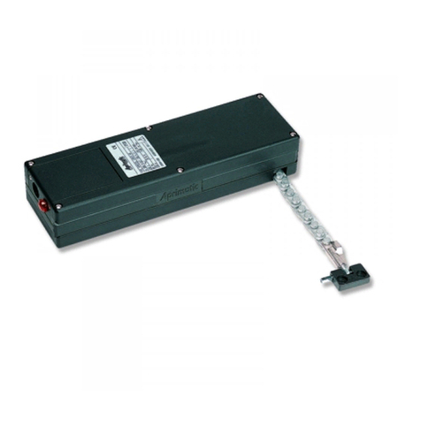
Attuatore elettrico in involucro di alluminio con movimento lineare
a stelo rigido. Funzionante a 230 VAC, provvisto di Þne corsa e
protezione termica. Collegabile in parallelo grazie all!utilizzo del
relè incorporato nella scheda. Provvisto di cavo di lunghezza 1,5m,
collegato all!interno dell!attuatore.Acorredo vengono fornite staffe
e supporti per l!applicazione richiesta.
ATTENZIONE
: Sono sconsigliate applicazioni con uso intensivo.
MAI installare due o più attuatori sullo stesso serramento!
IMPORTANTE:
quando si installa l’attuatore con corsa 400 mm è
assolutamente necessario corredare il sistema di un dispositivo
di rilevazione vento.
AVVERTENZA: Si ricorda che l’in"sso motorizzato deve ri-
spondere alla Direttiva Macchine e alla Direttiva Materiali per
costruzione.
FORNITURA DI SERIE
1A/1B
Attuatore . . . . . . . . . . . . . . . . . . . . . . . . . . . . . . . .Qt. 1
2Staffa anteriore . . . . . . . . . . . . . . . . . . . . Qt. 1
3Inserto di bloccaggio . . . . . . . . . . . . . . . . Qt. 2
4Anello esterno . . . . . . . . . . . . . . . . . . . . . Qt. 2
5Vite 6 x10. . . . . . . . . . . . . . . . . . . . . . . . . Qt. 2
6Attacco anteriore . . . . . . . . . . . . . . . . . . . Qt. 1
7Perno anteriore . . . . . . . . . . . . . . . . . . . . Qt. 1
8Dado esagonale M6+ rosetta dentellata . . . . Qt. 1
9Vite 6 x30. . . . . . . . . . . . . . . . . . . . . . . . . Qt. 1
10 Dado esagonale autobloccante M6 . . . . . Qt. 1
Dimensioni e ingombri degli accessori standard.
Dimensioni e ingombri:
vedi f.3-A per attuatore con corsa MAX 300 mm;
f.3-B per attuatore con corsa MAX 180 mm.
ST450N - ATTUATORE LINEARE A STELO
ATTENZIONE - Un!installazione non corretta può rendere l!attuatore pericoloso.AlÞne di evitare manovre errate con il rischio di incidenti e per garantire una più
lunga durata di funzionamento del prodotto, è importante leggere attentamente questo manuale, rispettando scrupolosamente le istruzioni fornite.
f.1
f.2
f.3
DESCRIPTION
Electric actuator in aluminium casing with rigid spindle linear drive.
It requires 230 Volt A.C., provided with limit switch and overload-
protection. It is supplied with a cable, 1.5 m in length, to which the
actuator is internally connected. Brackets and supports suitable for
the actuator's intended use are also provided.
WARNING
: this actuator is not recommended for intensive use.
Do not install two or more actuators on the same frame.
WARNING
:Whenyouinstalltheoperatorwith400mmtravel,you
MUST equip the system with a wind detection unit.
IMPORTANT
: The power-driven gate must comply with the Con-
struction Materials Directive and the Machine Directive.
STANDARD EQUIPMENT
1A/1B
Actuator. . . . . . . . . . . . . . . . . . . . . . . . . . . . . . . . .Qty 1
2Front bracket . . . . . . . . . . . . . . . . . . . . . . . . . . . .Qty 1
3Stopper . . . . . . . . . . . . . . . . . . . . . . . . . . . . . . . . .Qty 2
4External ring . . . . . . . . . . . . . . . . . . . . . . . . . . . .Qty 2
56 x 10 screw . . . . . . . . . . . . . . . . . . . . . . . . . . . .Qty 2
6Front Þxing joint . . . . . . . . . . . . . . . . . . . . . . . . . Qty 1
7Front pin . . . . . . . . . . . . . . . . . . . . . . . . . . . . . . . . Qty 1
8Hexagonal M6 nut + toothed washer . . . . . Qty 1
96 x 30 screw . . . . . . . . . . . . . . . . . . . . . . . . . . . .Qty 1
10 M6 self-locking hexagonal nut. . . . . . . . . . . .Qty 1
Dimensions and positions with standard accessories
Dimensions:
see f.3-A for actuator with MAX travel 300 mm;
f.3-B for actuator with MAX travel 180 mm.
ST450N - LINEAR SPINDLE ACTUATOR
CAUTION - Incorrect installation may be dangerous. To prevent operations that may result in accidents and to
grant a long life to the product read this manual and strictly obey the instructions provided.
INSTALLAZIONE
L!installazione dev!essere effettuata col serramento in
posizione chiusa.
1Tracciare la mezzeria del serramento. Fissare l!attacco all!inÞsso
utilizzando viti di Þssaggio idonee al materiale dell!inÞsso.
2Fissare la staffa supporto attuatore allineata con l!attacco
all!inÞsso, inoltre l!altezza deve essere tale che l!attuatore risulti
perpendicolare al serramento. Bloccare le viti di serraggio.
Assicurarsi che l!attuatore raggiunga correttamente le posizioni di
intervento Þne corsa senza ostacoli.
N.B. L!attuatore è fornito in posizione di Þnecorsa di chiusura.
COLLEGAMENTO ELETTRICO
Attuatore con alimentazione 230 volt c.a. ± 5&. Effettuare i
collegamenti elettrici come indicato nello schema di f.5a o 5b.
ATTENZIONE:
VeriÞcare l!esatta sezione dei cavi di alimentazione che
devonoessereopportunamentedimensionatiinbaseall!assorbimento
dell!attuatore.
Prevedere l!installazione di pulsanti commutatori, posizione OFF
centrale, con comando del tipo ad $uomo presente% o equivalente.
I pulsanti devono essere posti al di fuori del raggio di azione della
parte mobile del serramento.
ATTENZIONE:
La protezione termica del motore è una sonda di
controllo della temperatura degli avvolgimenti del motore elettrico.
Per una corretta protezione elettrica alimentare il motore tramite
interruttore magnetotermico con taratura del termico a 0,8 A e
del magnetico a 6A.
ATTENZIONE:
Se il CAVO di ALIMENTAZIONE è danneggiato, deve
essere sostituito dal costruttore o dal suo ServizioAssistenza Tecnica
o comunque da una persona con qualiÞca similare, in modo da
prevenire ogni rischio.
PERICOLO di schiacciamento delle mani! Durante il movimento
non interporre le mani fra il telaio Þsso e il battente.
I EN
INSTALLATION
The actuator must be installed when the window is closed.
1Mark the centre line on the window. Fix the block to the window
using screws suitable for the material the window is made of.
2Fix the actuator support bracket and the Þxing device to the
window so that they are in line.Their height must be adjusted so that
the actuator is perpendicular to the window. Tighten the screws.
Ensure that the actuator reaches the limit switch triggering positions
correctly and with no obstacles.
N.B. The actuator is supplied with the limit switch in the closing
position, with the window closed.
ELECTRICAL CONNECTION
Actuator with 230 volt A.C. + - 5&. Make the electrical con-
nections as indicated in the diagram f.5a or 5b.
WARNING
:
Check that the section of the power cable is adequate for
the actuator power requirements.
Arrange for the installation of changeover switches with mid OFF
position with $live-man% control or equivalent. The position of the
switch buttons must be outside the Þeld of action of the mobile
window.
WARNING
:
The motor overload protection is an electrical motor
coil temperature control probe. To ensure the electrical motor is
protected correctly, power the motor using the thermal-magne-
tic overload switch at a thermal setting of 0.8 A and a magnetic
setting of 6A.
WARNING: If the POWER CABLE is damaged, it must be replaced
by the manufacturer, or its service agent, or a similarly qualiÞed
person in order to avoid every hazard.
DANGER of hands being crushed!
When the window is moving, do
not
insert your hand between the Þxed frame and the mobile pane.
f.4
f.5
f.1
f.2
f.3
f.4
f.5
ST450N - ACTIONNEUR LINEAIRE A TIGE
ATTENTION- Unmontage incorrectpeutconstituerun danger.AÞn d!éviterdesopérations incorrectesetdenepasrisquer desaccidents sérieux
et aÞn de garantir une longue durée de vie du produit, lire attentivement ce manuel et respecter scrupuleusement les instructions fournies.
ST450N - LINEARSPINDELANTRIEBE
ACHTUNG - Eine fehlerhafte Installation kann eine Gefahrenquelle darstellen. Zur Vermeidung fehlerhafter Manöver mit Unfallgefahr ist es
wichtig, und zur gewährleistet eine lange Lebensdauer des Produkts dieses Handbuch aufmerksam durchzulesen und die darin enthaltenen
Informationen genauestens zu beachten.
F D
DESCRIPTION
Actionneur électrique linéaire à tige Þxe et enveloppe en aluminium.
Fonctionnant à 230 Volts c.a., muni d'un dispositif de Þn de course
et de protection thermique. Peut être raccordé en parallèle grâce à
un relais incorporé à la carte interne. Muni d'un câble d'alimenta-
tion d'une longueur de 1,5 m raccordé à l'intérieur de l!actionneur.
Sont également fournis les brides et les supports servant au type
de pose requis.
MISE EN GARDE
! Emploi intensif déconseillé.
Ne pas installer deux ou plusieurs vérins sur la même menuiserie!
PRUDENCE
:
Ilestnécessairedetoujourséquiperlesystèmed'un
dispositifpourladétectionduventlorsqu'onmonteunopérateur
avec une course de 400 mm.
IMPORTANT: ne pas oublier que le portail motorisé doit répon-
dre aux exigences de la Directive Machines et de la Directive
Matériaux de construction.
EQUIPEMENT STANDARD
1A/1B
Actionneur . . . . . . . . . . . . . . . . . . . . . . . . Q.té 1
2Bride avant. . . . . . . . . . . . . . . . . . . . . . . . Q.té 1
3Cale de blocage. . . . . . . . . . . . . . . . . . . . Q.té 2
4Anneau externe . . . . . . . . . . . . . . . . . . . . Q.té 2
5Vis 6 x 10 . . . . . . . . . . . . . . . . . . . . . . . . . Q.té 2
6Fixation avant. . . . . . . . . . . . . . . . . . . . . . Q.té 1
7Axe avant. . . . . . . . . . . . . . . . . . . . . . . . . Q.té 1
8Ecrou hexagonal M6 + rondelle dentée
. . . .
Q.té 1
9Vis 6 x 30 . . . . . . . . . . . . . . . . . . . . . . . . . Q.té 1
10 Ecrou hexagonal autobloquant M6 . . . . . Q.té 1
Dimensions et encombrements des accessoires standard.
Dimensions:
voir f.3-A
pour actionneur avec course MAXI 300 mm;
f.3-B
pour actionneur avec course MAXI
180 mm.
f.1
f.2
f.3
INSTALLATION
L'installation doit être effectuée avec le vantail fermé.
1Repérer le centre du vantail. Fixer l'attache sur le châssis à l'aide
de vis de Þxation adaptées au matériau du châssis.
2Fixer l'étrier de support de l'actionneur dans l'axe de l'attache
préalablement Þxée au châssis; la hauteur doit être telle que l'ac-
tionneur soit en position perpendiculaire par rapport au vantail.
Bloquer les vis de serrage.
VériÞer que l'actionneur atteint les positions de Þn de course sans
rencontrer d'obstacles
N.B. L'actionneur est livré en position de Þn de course de fermeture,
le vantail fermé.
BRANCHEMENT ELECTRIQUE
Actionneur alimenté en 230 volts c.a. (± 5&). Effectuer
les branchements électriques comme le montre le schéma de
f.5a ou 5b.
ATTENTION:
VériÞer le diamètre des Þls qui doit être sufÞsant pour
l'absorption électrique de l'actionneur.
Prévoir l!installation depoussoirscommutateurs,position OFF centrale,
avec commande du type $homme présent% ou équivalente. Les pous-
soirs doivent être hors du rayon d!action du vantail mobile.
ATTENTION:
La protection thermique du moteur est une sonde qui
contrôle la température des enroulements du moteur électrique.
Pourune bonneprotection électrique,alimenterlemoteurviaun
disjoncteur magnétothermique avec une protection thermique
réglée à 0,8A et une protection magnétique à 6A.
ATTENTION:
Encasdecâbled!alimentation endommagé,aÞnd!éviter
des risques, la substitution du câble doit être effectuée par le con-
structeur, ou par son Service d!Assistance, ou par un professionnel
de même qualiÞé.
DANGER d’écrasement des mains! Pendant le mouvement,
ne pas interposer les mains entre le châssis Þxe et le battant.
f.4
f.5
BESCHREIBUNG
Elekroantrieb in Aluminiumgehäuse mit linearem Spindeltrieb.
Betrieb bei 230 Volt Ws, ausgerüstet mit Endschaltern und Wärme-
schutzschalter. Parallel schaltbar über das Relais auf der Platine.
Zuleitungskabel im Antrieb angeschlossen, Länge 1,5 m. Bügel
und Konsolen für den gewünschten Verwendungszweck werden
mitgeliefert.
ACHTUNG! Für intensiven Gebrauch ungeeignet.
Auf dem selben Fenster sollten nicht 2 oder mehr Antriebe
angebracht werden.
VORSICHT
:WennderAntriebmitHub400mmmontiertwird,muss
das System unbedingt mit Windmelder ausgerüstet werden.
HINWEIS: Es wird darauf hingewiesen, dass das angetriebene
Tor der Maschinenrichtlinie und der Richtlinie für Baustoffe
entsprechen muss.
SERIENMÄSSIGER LIEFERUMFANG
1A/1B
Antrieb . . . . . . . . . . . . . . . . . . . . . . . . . . . 1 St.
2Vorderer Bügel . . . . . . . . . . . . . . . . . . . . . 1 St.
3Befestigungseinsätze. . . . . . . . . . . . . . . . 2 St.
4Ringe außen . . . . . . . . . . . . . . . . . . . . . . 2 St.
5Schrauben 6 x 10. . . . . . . . . . . . . . . . . . . 2 St.
6Vorderer Flügelbock. . . . . . . . . . . . . . . . . 1 St.
7Vorderer Stift . . . . . . . . . . . . . . . . . . . . . . 1 St.
8
Sechskantmutter M6 + gezahnter Unterlegscheibe
1 St.
9Schraube 6 x 30. . . . . . . . . . . . . . . . . . . . 1 St.
10 Selbstsperrende Sechskantmutter. . . . . . 1 St.
Abmessungen und Platzbedarf des Standardzubehörs.
Abmessungen:
siehe f.3-A
bei Max. Hub 300mm;
siehe f.3-B
bei Max. Hub 180mm.
f.1
f.2
f.3
INSTALLATION
Die Installation muß bei geschlossenem Fenster erfolgen.
1
Die Mittellinie
des Fensters anzeichnen. Den Flügelblock mit für das
Material
des Fensterßügels geeigneten Schrauben anschrauben.
2Die Schiebekonsole mit dem Flügelbock geßuchtet montieren.
Die Höhe muß so gewählt werden, daß derAntrieb senkrecht zum
Fenster steht. Die Feststellschrauben anziehen.
Versichern sie sich, daß derAntrieb seine Endlage unbehindert erreicht.
HINWEIS: Der Antrieb wird in Schließendstellung geliefert, das
Fenster ist geschlossen.
STROMANSCHLUSS
Antrieb 230 Volt Ws ± 5&. Die elektrischen Anschlüsse
gemäß f.5a oder 5b Plan durchführen.
ACHTUNG:
Den Querschnitt des Zuleitungskabels prüfen, der der
Stromaufnahme desAntrieb angepaßt sein muß.
BeiderInstallationmüssenverriegelteUmschalttasten,zentraleOFF-
Position mit einer $Totmannvorrichtung%- Schaltung o.ä. bereitgestellt
werden. Die Position der Umschalttasten sich außerhalb des
Wirkungsradius des beweglichen Teils des Fensters beÞnden.
ACHTUNG:
BeimMotorschutzschalterhandeltessichumeinenFühler
zur Temperaturüberwachung der Wicklungen des Elektromotors.
Für einen ordnungsgemäßen elektrischen Schutz muss die
Einspeisung des Motors über einen thermisch-magnetischen
SchutzschaltermitthermischerAuslösung bei0,8Aundmagne-
tischer Auslösung bei 6 A erfolgen.
ACHTUNG:
Wenn das Versorgungskabel beschädigt wird, muss es
durch den Konstrukteur oder von dessen Kundendienst, jedenfalls
jedochvoneinerdazuqualiÞziertenPersonersetzt werden,um jedem
Risiko vorzubeugen.
GefährdungdurchQuetschenderHände!WährendderBewegung
des Flügels nicht die Hände zwischen Rahmen und die beweglichen
Teile bringen.
f.4
f.5
DESCRIPCIÓN
Actuador eléctrico con envoltura de aluminio, con movimiento lineal
y barra rígida. Funcionamento a 230 Volt. C.A. dotado de Þn de
carrera y protegido térmicamente. Se puede conectar en paralelo
gracias a la utilización del relé incorporado en la tarjeta. Equipado
con cable conectado en el interior del actuador, de longitud 1,5 m.
Se suministran los estribos y soportes para la aplicación especíÞca.
ATENCIÓN
: Se desaconsejan aplicaciones para uso intensivo.
No instalen dos o más servomotores en el mismo cerramiento.
PRECAUCIÓN: Cuando se instala el actuador con 400 mm de carrera
es absolutamente necesario equipar el sistema con un dispositivo de
detección del viento
.
ATENCIÓN
:Caberecordarquelosmarcosmotorizadosdepuertas
y ventanas tienen que cumplir con la Directiva Máquinas y con la
Directiva Materiales de construcción.
EQUIPAMIENTO DE SERIE
1A/1B
Actuador . . . . . . . . . . . . . . . . . . . . . . . . . . . . . . . .1 Pz.
2Estribo anterior . . . . . . . . . . . . . . . . . . . . . . . . . .1 Pz.
3Inserción de Þjación . . . . . . . . . . . . . . . . . . . . . 2 Pz.
4Anilla exterior . . . . . . . . . . . . . . . . . . . . . . . . . . . 2 Pz.
5Tornillos 6 x10. . . . . . . . . . . . . . . . . . . . . . . . . . . 2 Pz.
6Unión anterior . . . . . . . . . . . . . . . . . . . . . . . . . . . 1 Pz.
7Perno anterior . . . . . . . . . . . . . . . . . . . . . . . . . . .1 Pz.
8Tuerca hexagonal M6 + arandela dentada . . . . 1 Pz.
9Tornillo 6 x30 . . . . . . . . . . . . . . . . . . . . . . . . . . . .1 Pz.
10 Tuerca hexagonal autobloqueante M6. . . .1 Pz.
Dimensiones por los accesorios estándares.
Dimensiones:
veer f.3-A para actuador con carrera máx 300mm.
f.3-B para actuador con carrera máx 180 mm.
ST450N - ACTUADOR LINEAL DE BARRA
ATENCIÓN- Una instalación equivocada puede ser una fuente de peligro. Con el Þn deevitarmaniobrasequivocadascon riesgodeaccidentey
paragarantizarunamayorduracióndefuncionamientodelproducto,esimportanteleeratentamenteestemanual,respetandoescrupulosamente
las informaciones suministradas.
f.1
f.2
f.3
INSTALACIÓN
La instalación debe ser efectuada con el cerramiento en la
posición de cierre.
1Marcar la línea de centro del cerramiento. Fijar la unión al marco
utilizando tornillos de Þjación idóneos al material del marco.
2Fijar el estribo de soporte del actuador alineado con la unión en el
marco,ademáselotrodebeestarcolocadodemodotalqueelactuador
resulte perpendicular al cerramiento. Montar los tornillos de Þjación.
Asegurarse de que el actuador alcance correctamente las posicio-
nes de activación del Þn de carrera sin obstáculos.
NOTA
:
El actuador se suministra en posición de Þn de carrera de cierre.
CONEXIÓN ELÉCTRICA
Actuador con alimentación 230 volt c.a. ± 5&. Realizar las
conexiones eléctricas según el esquema de f.5a o 5b.
ATENCIÓN:
VeriÞcarlasecciónexactadeloscablesdealimentaciónque
deben ser dimensionados en base a la absorción del actuador.
Prevean la instalación de pulsadores conmutadores, posición OFF
central, con mando del tipo $hombre presente% o equivalente. Los
pulsadores deben situarse fuera del radio de acción de la parte
móvil del cerramiento.
ATENCIÓN:
La protección térmica del motor es una sonda de
control de la temperatura de los devanados del motor eléctrico.
Para una protección eléctrica adecuada, alimentar el motor me-
diante un interruptor magnetotérmico con el térmico calibrado a
0,8A y el magnético a 6 A.
ATENCIÓN:
enel caso enqueelCABLEdealimentaciónresultedaña-
do, la sustitución debe ser efectuada por el constructor o su Servicio
Técnico o de todas maneras por personal caliÞcado de igual manera,
para prevenir cualquier riesgo.
PELIGRO de aplastamiento de las manos! Durante el movimiento
no coloquen las manos entre el marco Þjo y el batiente.
E
f.4
f.5
CARATTERISTICHE TECNICHE
Forza di spinta e trazione nominale: 300 N
Forza MASSIMAdi spinta e trazione: 450 N*
*
consentita per: tempo di lavoro 30 sec. e tempo di sosta 2 minuti.
MASSIMA corsa disponibile (mm): 180 300
Durata corsa a vuoto (sec.): 7 12
Velocità di traslazione: 23 mm/sec
Tensione monofase: 230
Volt c.a. ± 5&
Corrente: 0,7 A
Consumo: 150 Watt
Condensatore: 1 per 5 F
Frequenza: 50 Hz
Protezione termica: SI
Fine corsa automatico: SI
Relais incorporato: SI
Collegabile in parallelo: SI
Grado di protezione: lP 55 (per interni)
Veri!care che l’attuatore prescelto sia adeguato all’applicazione prevista.
I
SPECIFICATIONS
Nominal thrust and traction force: 300 N
MAX thrust and traction force: 450 N*
*
admitted with: 30 sec. work time and 2 minutes pause time.
MAX available travel (mm): 180 300
Length of time for idle travel (sec.): 7 12
Linear speed: 23 mm/sec
Single phase voltage: 230 Volts ~ ± 5&
Current: 0,7 A
Consumption: 150 Watts
Condenser: 1 for 5 F
Frequency: 50 Hz
Overload switch: YES
Automatic limit switch: YES
Built-in relay: YES
Parallel connection: YES
Protection rating: lP 55 (for indoors)
Check to be sure the selected actuator is suitable for your application.
EN
DATOS TÉCNICOS
Fuerza de empuje y tracción nominal: 300 N
Fuerza MÀXIMAde empuje y tracción: 450 N*
*
permitida con: tiempo de trabajo 30 seg. y tiempo de sosta 2 minutos.
MÀXIMA carrera disponible (mm): 180 300
Duración carrera en vacío (seg.): 7 12
Velocidad lineal: 23 mm/seg.
Tensión monofásica:
230 Voltios ~ ± 5&
Corriente: 0,7 Amperios ~
Consumo: 150 Vatios
Condensador: 1 por 5 F
Frecuencia: 50 Hz
Protección térmica: SI
Fin de carrera automático: SI
Relé incorporado: SI
Conexión en paralelo: SI
Grado de protección: lP55(
paraelinterior
)
Comprueben que el actuador elegido sea adecuado a la aplicación prevista.
E
CARACTÉRISTIQUES TECHNIQUES
Force de poussée et de traction nominale: 300 N
Force MAXIME de poussée/traction: 450 N*
*
autorisée avec temps de travail de 30 sec. et pause de 2 minutes.
Course disponible MAXI (mm): 180 300
Durée course à vide (s): 7 12 16
Vitesse linéaire: 23 mm/s
Tension monophasée:
230 Volt c.a. ± 5&
Courant: 0,7 A ~
Consommation: 150 Watts
Condensateur: 1 pour 5 F
Fréquence: 50 Hz
Protection thermique: OUI
Fin de course automatique: OUI
Relais incorporé: OUI
Branchement en parallèle: OUI
Degré de protection: lP55(
pourl!intérieur
)
Véri!er si le vérin choisi convient pour l’application prévue.
FTECHNISCHE DATEN
Druck- und Zugkraft nominal: 300 N
MAXIMALE Schub- und Zugkraft: 450 N*
*gewährleistet wenn: Arbeitszeit = 30 Sek. und Stillstandszeit = 2 min.
MAX Hübe (mm): 180 300
Leerwegdauer (sek.): 7 12
Laufgeschwindigkeit: 23 mm/sek.
Einphasenspannung: 230 Volt ~ ± 5
Stromstärke: 0,7 A ~
Stromverbrauch: 150 Watts
Kondensator: 1 mal 5 F
Frequenz: 50 Hz
Warmeschutz: JA
Autom. Endschalter: JA
Eingebautes Relais: JA
Parallelschaltbar: JA
Schutzart: lP55
(fürdenInnenbereich)
Die Eignung des gew ähltenAntriebs hinsichtlich der voraus-
sichtlichen Anwendung ist zu prüfen.
D
Esempi di montaggio / Exemples of installation / Exemples de montage / Installation Beispiel / Ejemplos de montaje
SI/YES
OUI/JA/SÍ
SI/YES
OUI/JA/SÍ
NO/NON
NEIN/NO
ERRORE!L!attuatorenonpuòruotare#ERROR!Theactuator
cannotturn#ERREUR!Levérinnepeutpastourner#FEHLER!
Der Antrieb kann sich nicht drehen# ¡ERRORE! El actuador
no puede girar#
NO/NON
NEIN/NO
ERRORE! Montaggio fuori asse# ERROR! Assembly is misa-
ligned# ERREUR! Montage désaxé# FEHLER! Achsenfalsche
Montage des Antriebs# ¡ERRORE! Montaje fuera del eje#
IMPORTANTE!
In fase di apertura l!attuatore necessita di spazio per ruotare.
Assicurarsi che l!attuatore raggiunga correttamente le posizioni di
interventoÞnecorsainaperturae inchiusurasenza ostacoli(Þnecorsa
inchiusura=stelocompletamenterientrato;Þnecorsainapertura=stelo
completamente uscito).
IMPORTANT!
The actuator needs space to turn during opening.
Ensure that the actuator reaches the opening and closing limit switch
triggeringpositions correctlyand withnoobstacles(closinglimitswitch
= rod completely retracted; opening limit switch = rod completely
extended).
IMPORTANT!
L!actionneur exige un certain espace pour tourner pendant l!ouverture.
VériÞerque l!actionneuratteint lespositionsdeÞndecourseenferme-
ture et en ouverture sans rencontrer d!obstacles (intervention de la Þn
decourse:en fermeture= avectige entièrementrentrée;enouverture
= avec tige entièrement étendue).
WICHTIG #
DerAntrieb ben ötigt während der Öffnung den für die Drehung.
Versichern sie sich, daß der Antrieb seine Endlage unbehindert erreicht
(Endlage offen = Schaft vollständig ausgefahren; Endlage geschlossen =
Schaft vollständig eingezogen).
¡IMPORTANTE!
El actuador necesita un espacio para girar durante la apertura.
Comprobar de que el actuador alcance correctamente las dos posiciones
de accionamiento del Þnal de carrera sin obstáculos (Þnal de carrera del
cierre= barra completamente recogida; Þn de carrera de la apertura
=
barra
completamente extendida).


